You already know that computers store and interpret data in binary: ones and zeroes. There are many, many ways to store binary data, because it works with anything that can maintain at least two states. In the early days of computing, punch cards were common. They were paper cards with a grid of points. A hole at any of those points could represent either a one or zero (depending on the system), while the lack of a hole would represent the opposite. To bring old and new together, Nino Ivanov built an Arduino punch card reader for cloud computing.
Cloud computing turns processing into an internet service, letting customers run whatever calculations or programs they like without needing to maintain their own hardware. In a typical use case scenario, the customer would simply upload their code or data from a computer to the cloud service for processing. But that data can come from anything, including punch cards. Ivanov’s project uses punch cards (which he seems to have cut by hand) that are read by an Arduino, transferred to a computer, and then entered into the cloud computing terminal interface.
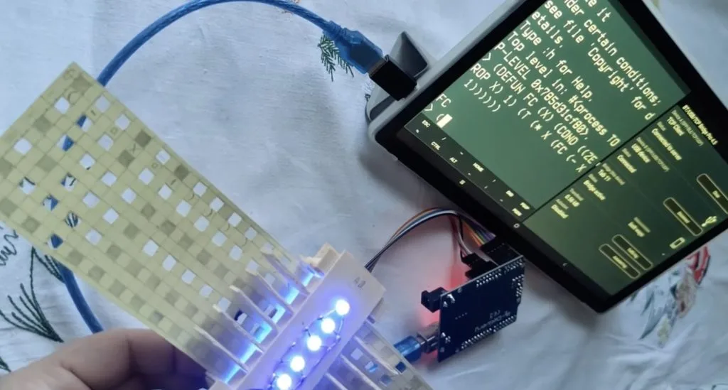
Each punch card is just a piece of grid paper with some squares cut out. Each row contains six bits, which an Arduino Uno reads using a cobbled-together reader made with LEDs and photoresistors. If there is a square cut out, the light will pass through and the corresponding photoresistor will detect the light. A small servo motor feeds the punch card through the reader. In this case, Ivanov encoded a Common Lisp program to process factorials in the cloud. But the same general concept could apply to any language or data — though most are much less efficient than Lisp and would require a far greater number of punch cards.
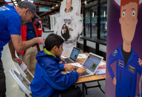
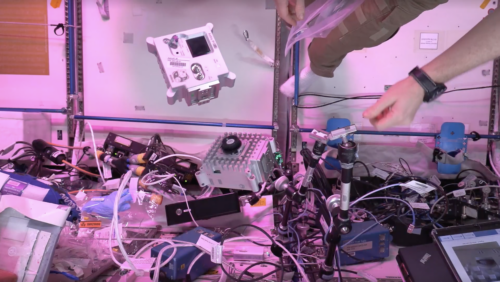
In the Columbus module of the International Space Station (ISS), there are two Astro Pi computers called Marie Curie and Nikola Tesla. These computers run the programs young people create as part of the annual European Astro Pi Challenge.
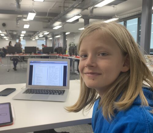
For this year’s Astro Pi Mission Zero, young people sent us over 15,000 programs to show the ISS astronauts colourful images and animations of animals and plants on the Astro Pi displays and remind them of home.
A space mission inspired by nature
Mission Zero is a free beginners’ coding activity. It gives young people the unique opportunity to follow our step-by-step guide to write a simple program in Python that can run in space on the ISS orbiting planet Earth.
The Astro Pi computers on board the ISS
The Mission Zero activity this year was to write code to use the Astro Pi’s colour sensor to measure the lighting conditions in the Columbus module, and to then use that measurement to set a colour in an image or animation on the Astro Pi’s 8×8 LED display. We invited young people to design images of fauna and flora to give the astronauts on board the ISS a reminder of the beautiful creatures, plantlife, and landscapes found on planet Earth.
The Mission Zero activity is ideal for learners trying text-based programming for the first time. It covers some key programming concepts, including variables, sequence, and iteration.
This year we received 15,551 Mission Zero programs, and after carefully checking them against the entry and safety criteria, we were able to run 15,475 programs. They were sent to us by 23,605 learners working in teams or independently, and 10,207 of this year’s participants were girls.
This year the most Mission Zero programs came from young people in the UK, followed by Spain, France, Italy, and Greece. Lots of different organisations supported young people to take part, including publicly funded primary and secondary schools, as well as educator- and volunteer-led Code Clubs and CoderDojos we support.
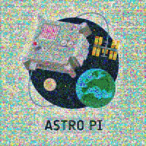
We’re celebrating the many different people involved in this year’s mission with a mosaic of the Mission Zero logo made up of lots of the inspiring designs participants sent us. You can explore an interactive version of the image too!
A mosaic of Mission Zero designs
All of the participants whose programs ran on the ISS will be receiving a certificate to recognise their efforts, which will include the time and coordinates of the ISS when their program ran. Programs created by young people from across Europe ran on board the ISS in the final week of May.
If you enjoyed Astro Pi Mission Zero this year, we would be delighted to see you again in the next annual round. If you’re feeling inspired by the images young people have created, we invite you to get involved too. We provide guides and help for all adult mentors who want to support young people to take part, and the step-by-step guide for coding a Mission Zero program in 19 European languages.
The activity of designing an image has been really popular, and we have been super impressed with the creativity of young people’s designs. That’s why we’ll be running Mission Zero in the same format again starting in September.
If you’d like to hear news of the Astro Pi Challenge, please sign up to the newsletter on astro-pi.org:
We are always interested to hear your feedback about Mission Zero, as a mentor or participant. If you would like to share your thoughts with us, please email enquiries@astro-pi.org.
PS Look out for some cool news about the Astro Pi computers, which we’ll announce soon on this blog!
Evolution is fact — at least as much as anything is a “fact” in the scientific sense. What is still very much in question is abiogenesis, which is the origin of life from inorganic compounds. Evolution is the mechanism that took unicellular life to our current biodiversity, but scientists don’t know exactly how the first single-cell organisms came to be. Most reputable theories posit that the conditions on a young Earth allowed organic compounds, like amino acids, to form and then develop into organisms. In 1952, the Miller-Urey experiment confirmed that such a thing is possible. To recreate that famous experiment, M. Bindhammer turned to Arduino.
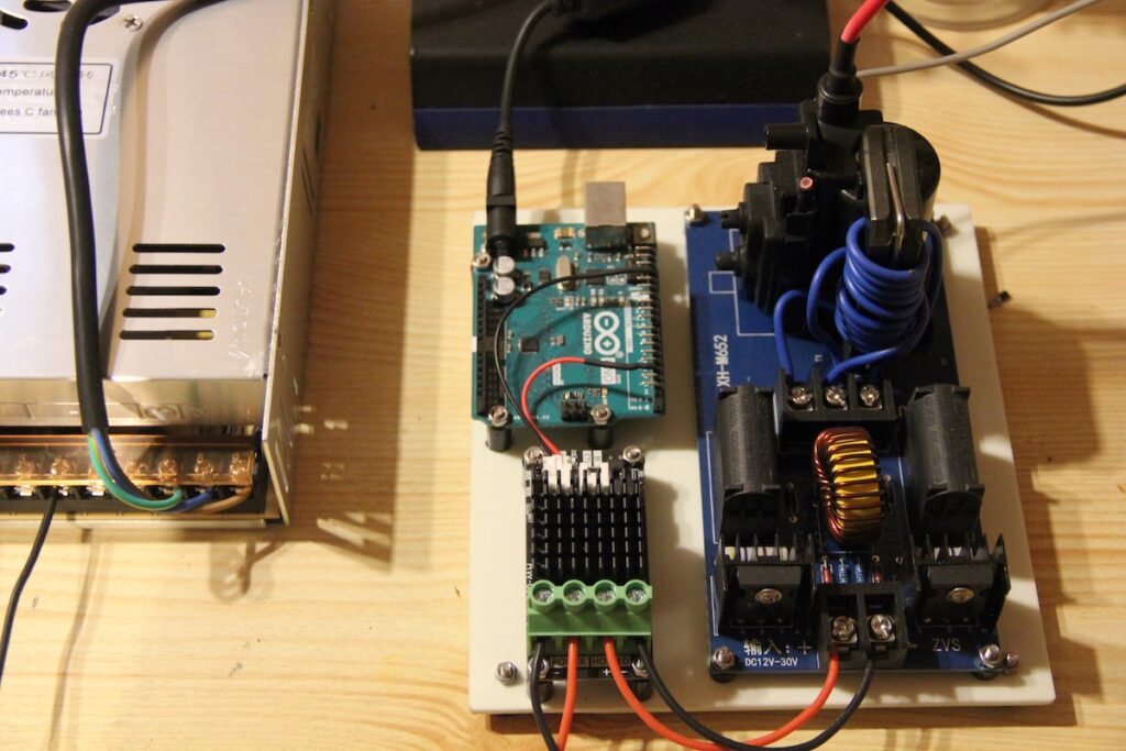
The conditions that, theoretically, resulted in the first amino acids were an atmosphere of compounds like methane, water, ammonia, and hydrogen along with electricity in the form of lightning. Stanley Miller, under the supervision of Harold Urey, recreated those conditions in the lab with a closed system that heated the gases, passed them through a chamber with electrodes to produce sparks, then down through a cooler and back to the start. That produced many amino acids that could (again, in theory) come together to form genetic code. M. Bindhammer’s reproduction of this experiment works in a similar way, but with a plasma arc instead of sparks.
M. Bindhammer needed a way to control the plasma arc and chose an Arduino Uno Rev3 board for the job. That plasma arc oxidizes the nitrogen in the air, so it is crucial to the experiment. Generating the plasma arc required a lot of voltage (45000V), which M. Bindhammer controlled through a MOSFET connected to the Arduino. That let them modulate power to the electrodes in order to avoid overheating them.
This seems to have been a success and M. Bindhammer reports that the initial experiment produces the hypothesized results.
Artificial intelligence (AI) and natural language processing (NLP) are changing the way we interact with technology. With advancements in machine learning and data processing, we now have AI-powered virtual assistants, chatbots, and voice recognition systems that can understand and respond to our queries in a natural, human-like way. One such technology is ChatGPT, a large language model developed by OpenAI based on the GPT-3.5 architecture. ChatGPT has the ability to generate coherent, context-aware responses to a wide range of questions, making it an ideal tool for communication.
Integrating ChatGPT and Arduino Cloud for IoT projects
Integrating ChatGPT and the Arduino Cloud, a platform that allows you to develop, deploy and manage IoT devices in the easiest way, opens up a brand new world of possibilities for IoT applications. By combining ChatGPT’s natural language processing capabilities with the Arduino Cloud’s IoT platform, we can create intelligent devices that can understand and respond to natural language queries, making the user experience more seamless and intuitive. For example, imagine a smart home system that can be controlled using voice commands, or a chatbot that can provide instant technical support for IoT devices.
Chat with ChatGPT through Arduino IoT Cloud dashboards
This project is a simple demonstration of an Arduino IoT Cloud-compatible device, such as an Arduino Nano RP2040 Connect or any ESP32/ESP8266 device, acting as a middleware between the IoT Cloud and OpenAI’s GPT-3.5 language model. The device acts as a bridge by receiving prompts (questions) from the IoT Cloud and forwarding them to the OpenAI API. Once the model processes the prompts, the device receives and parses the replies and sends them back to the IoT Cloud, which displays the response to the user.
To embark on this project, you will need to create an OpenAI account, create an API key, and have enough credits. Then, you can create your device on the IoT Cloud, program it, and set up the dashboard on the IoT Cloud. The dashboard serves as a user interface, allowing you to write questions (prompts) and receive ChatGPT’s replies.
Check out the project on Arduino’s Project Hub and get more information about how to build the system yourself.
As you get into the project, you can explore variable tweaking, defining the maximum number of tokens that ChatGPT will use in generating a response, and keeping in mind the limits on OpenAI API usage. Overall, this project presents a unique opportunity to integrate the cutting-edge capabilities of OpenAI’s language model with the versatile Arduino IoT Cloud, enabling you to create more intelligent and intuitive IoT applications.
Connect to ChatGPT using MicroPython
If you are interested in an alternative approach of connecting to ChatGPT, you can do so by using a MicroPython script. If you are familiar with making HTTP requests using Python, this is a great approach.
To authenticate and successfully make requests with ChatGPT, you will need to first get your API key from OpenAI, and construct a POST request. We will be using the urequests and ujson modules, where we will simply ask a question to ChatGPT, and get a response.
The response is printed on a 128×64 OLED display, and that’s pretty much it. It is a minimal example, but a fun one, and easy to get started with.
To get started with MicroPython and ChatGPT, visit this repository which has the code and instructions to get started.
This type of integration paves the way for many cool projects. You can for example ask ChatGPT to evaluate recently recorded data, or a companion-bot that knows everything that the Internet knows..
Introducing the Arduino Cloud
The Arduino Cloud is a platform that simplifies the process of developing, deploying, and managing IoT devices. It supports various hardware, including Arduino boards, ESP32, and ESP8266 based boards, and makes it easy for makers, IoT enthusiasts, and professionals to build connected projects without coding expertise. What makes Arduino Cloud stand out is its intuitive interface that abstracts complex tasks, making it accessible to all users. With its low-code approach and extensive collection of examples and templates, Arduino Cloud offers a simple way for users to get started.
The platform’s IoT Cloud tool allows for easy management and monitoring of connected devices through customizable dashboards, which provide real-time visualisations of the device’s data. Furthermore, the IoT Cloud can be accessed remotely through the mobile app Arduino IoT Cloud Remote, which is available for both Android and iOS devices, enabling users to manage their devices from anywhere.
Build your own
The integration of ChatGPT and Arduino Cloud has opened up a new world of opportunities for IoT applications. These projects are just some examples of how these technologies can be used to create intelligent devices that can understand and respond to natural language queries.
If you have been inspired by these projects and want to share your own creation with the community, we encourage you to publish your project on Arduino Project Hub. By doing so, you can showcase your project and share your knowledge with others. Arduino Project Hub is a platform where users can share their Arduino-based projects and find inspiration for new ones. With a global community of makers and enthusiasts, the hub is the perfect place to collaborate, learn and explore the endless possibilities of IoT. So, whether you are a seasoned maker or just starting, we invite you to join our community and share your project with the world!
Designing, constructing, and launching your own model rockets is a great hobby for learning more about the world of aerodynamics, computer simulations, and physics as a whole. But when it comes to actually lighting the solid rocket fuel to achieve ignition, the user normally lights a fire directly on a fuse or lays out a reel of wire to electronically burn the propellent, both of which are not ideal.
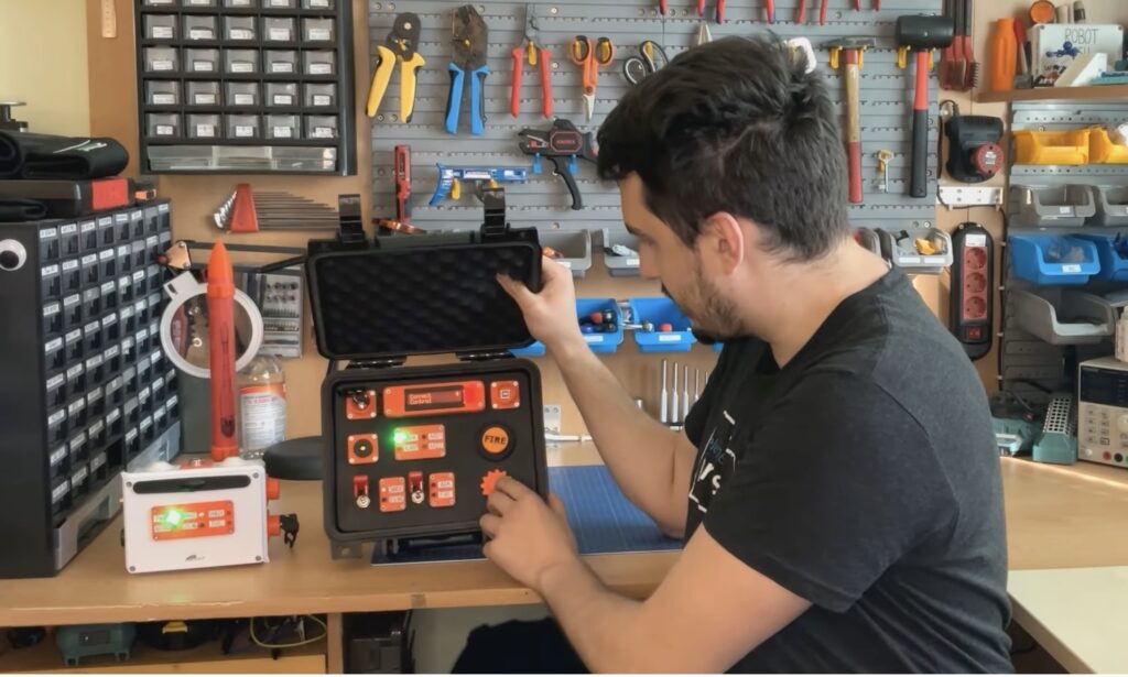
Milos Rasic of element14 Presents, in contrast, had the idea to create a remotely-operated launching system that would allow the user to simply flick a switch and press a button to achieve lift-off without the need for kilometers of wire. His ignition circuit relied on an Arduino MKR WAN 1310 to receive commands over LoRaWAN and the board, in turn, would begin charging a pair of supercapacitors via a series of MOSFETs, relays, and op-amps until they each reached about 8V. Once everything had been tested on a breadboard, Rasic soldered his components onto perfboard and arranged them inside a custom weatherproof case.
On the controller side, Rasic grabbed another MKR WAN 1310 and connected a 16×2 LCD display, a rotary encoder for making selections, and an array of switches and buttons for selecting when the system is charging, armed, and igniting the rocket. Better yet, the model rocket was also a custom design along with the launchpad.
To see this system in action, check out Rasic’s video below!
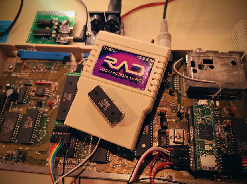
For those unaware, the REU plugged into the C64’s expansion port and added extra memory while also allowing for direct memory access (DMA) transfers – something the Sidekick64 couldn’t do. This meant data could be transferred to and from the main system memory whole bypassing the MOS Technology 6510/8500 CPU. “My RAD Expansion Unit was designed to do these transfers,” Carsten says. It’s a major triumph!
Radical thinking
There are many benefits to having the RAD Expansion Unit, which boosts the amount of available memory from the standard 64kB to as much as 16MB. “It helps to run Geos [a C64 OS] and it makes some tasks less annoying, such as copying disks in one go. It also functions as a RAM disk to accelerate working with the system,” Carsten says.
In order to create the project, then, two PCBs were produced: one to fit Raspberry Pi 3A+/3B+ and another to fit Raspberry Pi Zero 2 W (the latter creating a less expensive unit). “I didn’t want the glue logic that facilitates the bus communication with the available GPIOs to get too extensive and I wanted to avoid Complex Programmable Logic Devices and such which would prevent many people from building their own RAD,” Carsten says.
Indeed, the project was designed so that the RAD contains the glue logic to interface Raspberry Pi with the C64 bus. “You simply put it on to Raspberry Pi like a HAT and plug it into the expansion port of the Commodore 64,” Carsten continues. “The combination of a fast SoC and a decent number of GPIOs was great.”
An explosive result
There were challenges, of course. “The biggest was getting the bit banging right,” Carsten says. “Most of the communication has to happen within a time window of less than 500 nanoseconds – most often there’s significantly less time between all signals being read and putting data on the bus.”
To make the device run smoothly, Carsten had to use multiplexers. “More signals on the expansion port need to be read/written to than Raspberry Pi has GPIOs,” he explains. The correct data had to be put on the bus at the right time to prevent memory corruption and, in the worst case, random instructions being executed by the CPU, causing a crash. “In general, to get the timing right, I needed to hit intervals at a spacing of approximately tens of nanoseconds, which I did using CPU cycle counters.”
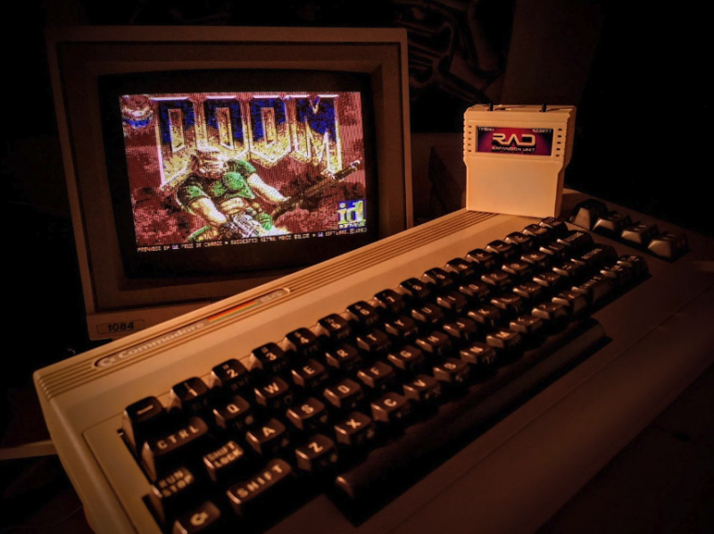
With all that in place, it was time to chill and RAD-Doom proved a great way to do so. Most of the processing is being done by Raspberry Pi (“it’s essentially a CPU replacement where the new CPU is a one-core ARM running at 1.4GHz with its own 512MB RAM,” Carsten says). But the important thing is that the tech demo uses the C64’s VIC-II graphics chip – and works! Sound is also streamed to the iconic SID chip.
“I wanted to see how the C64/C128’s VIC-II and SID performed if CPU power and memory was not an issue,” Carsten says. “I also wanted to experiment with real-time colour dithering for the VIC-II.” By making use of Doom to output graphics and sound, he’s certainly managed to achieve that.
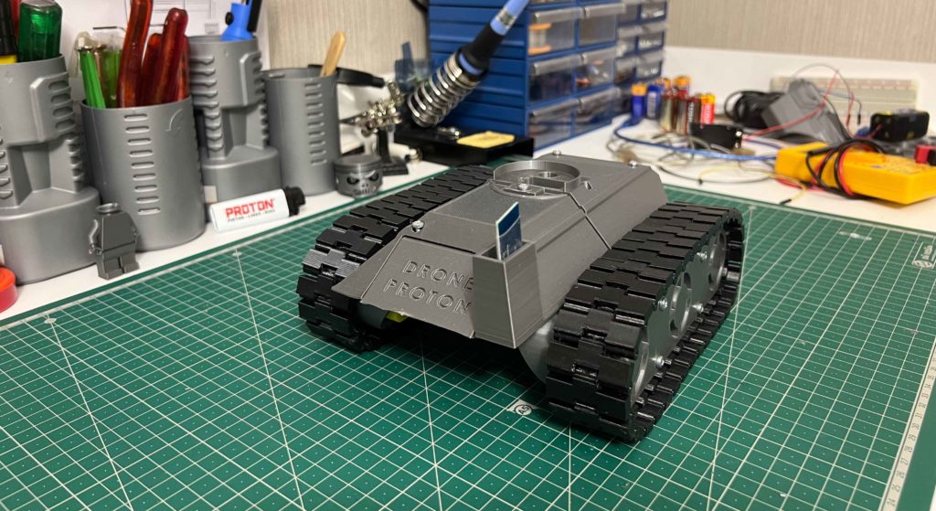
This is the third time that we’ve selected three outstanding projects in the Arduino Project of the Month competition, highlighting the wide range of our users’ contributions to our growing Project Hub. For April we go from tanks to tunes – because why not? Anything is possible with just a few components, a lot of curiosity, and an amazing community like ours.
If you’re on a mission to build a remote-controlled tank, this is the project for you! Complete with downloadable code, electronics diagram and 3D models, it even provides easy instructions in video format. Use an Arduino Nano, four DC motors, a motor driver, and Bluetooth® module to fight the good fight of making!
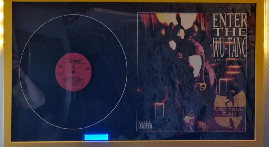
Thanks to this project, you can display your favorite record and listen to it too! Add small hidden speakers and a touch-sensitive button to your vinyl frame, and play MP3 tracks off a DFPlayer SD card. With an Arduino Nano, the Arduino IDE, and clear and simple instructions, you can recreate or customize this project without skipping a beat.
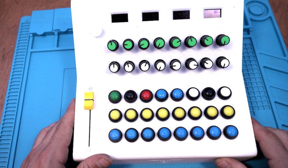
DIYing your own MIDI controller is cheaper than buying one off the shelf and, of course, is hugely satisfying for any music-oriented maker. With this Arduino Due project, it might even be easier than you think! Check out this entry’s in-depth tutorial to make a USB MIDI controller for all the basic parameters of a digital audio workstation (DAW) — volume, pan, mute, solo, rec, play, stop and more — without assigning anything manually.
For your chance to be selected for a $100, $300 or even $500 gift card to spend on the Arduino Store, submit your best project on the Project Hub! We will be awarding three new entries every month, as detailed in the complete terms and conditions. Good luck!
What do we talk about when we talk about artificial intelligence (AI)? It’s becoming a cliche to point out that, because the term “AI” is used to describe so many different things nowadays, it’s difficult to know straight away what anyone means when they say “AI”. However, it’s true that without a shared understanding of what AI and related terms mean, we can’t talk about them, or educate young people about the field.
They ensure that we give learners and teachers a consistent and clear understanding of the key terms across all our Experience AI resources. Within the Experience AI Lessons for Key Stage 3 (age 11–14), these key terms are also correlated to the target concepts and learning objectives presented in the learning graph.
They help us talk about AI and AI education in our team. Thanks to sharing an understanding of what terms such as “AI”, “ML”, “model”, or “training” actually mean and how to best talk about AI, our conversations are much more productive.
As an example, here is our explanation of the term “artificial intelligence” for learners aged 11–14:
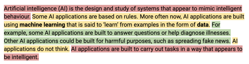
Artificial intelligence (AI) is the design and study of systems that appear to mimic intelligent behaviour. Some AI applications are based on rules. More often now, AI applications are built using machine learning that is said to ‘learn’ from examples in the form of data. For example, some AI applications are built to answer questions or help diagnose illnesses. Other AI applications could be built for harmful purposes, such as spreading fake news. AI applications do not think. AI applications are built to carry out tasks in a way that appears to be intelligent.
You can find 32 explanations in the glossary that is part of the Experience AI Lessons. Here’s an insight into how we arrived at the explanations.
Reliable sources
In order to ensure the explanations are as precise as possible, we first identified reliable sources. These included among many others:
Explaining AI terms to Key Stage 3 learners: Some principles
Vocabulary is an important part of teaching and learning. When we use vocabulary correctly, we can support learners to develop their understanding. If we use it inconsistently, this can lead to alternate conceptions (misconceptions) that can interfere with learners’ understanding. You can read more about this in our Pedagogy Quick Read on alternate conceptions.
Some of our principles for writing explanations of AI terms were that the explanations need to:
Be accurate
Be grounded in education research best practice
Be suitable for our target audience (Key Stage 3 learners, i.e. 11- to 14-year-olds)
Be free of terms that have alternative meanings in computer science, such as “algorithm”
We engaged in an iterative process of writing explanations, gathering feedback from our team and our Experience AI project partners at Google DeepMind, and adapting the explanations. Then we went through the feedback and adaptation cycle until we all agreed that the explanations met our principles.
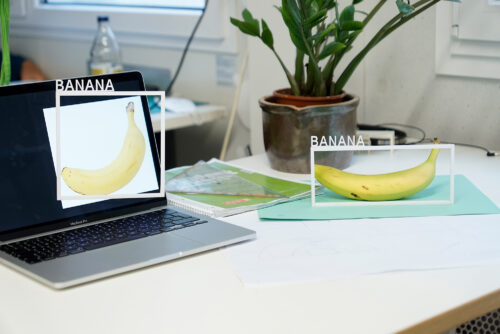
Image: Max Gruber / Better Images of AI / Ceci n’est pas une banane / CC-BY 4.0
An important part of what emerged as a result, aside from the explanations of AI terms themselves, was a blueprint for how not to talk about AI. One aspect of this is avoiding anthropomorphism, detailed by Ben Garside from our team here.
As part of designing the the Experience AI Lessons, creating the explanations helped us to:
Decide which technical details we needed to include when introducing AI concepts in the lessons
Figure out how to best present these technical details
Settle debates about where it would be appropriate, given our understanding and our learners’ age group, to abstract or leave out details
Using education research to explain AI terms
One of the ways education research informed the explanations was that we used semantic waves to structure each term’s explanation in three parts:
Top of the wave: The first one or two sentences are a high-level abstract explanation of the term, kept as short as possible, while introducing key words and concepts.
Bottom of the wave: The middle part of the explanation unpacks the meaning of the term using a common example, in a context that’s familiar to a young audience.
Top of the wave: The final one or two sentences repack what was explained in the example in a more abstract way again to reconnect with the term. The end part should be a repeat of the top of the wave at the beginning of the explanation. It should also add further information to lead to another concept.
Most explanations also contain ‘middle of the wave’ sentences, which add additional abstract content, bridging the ‘bottom of the wave’ concrete example to the ‘top of the wave’ abstract content.
Here’s the “artificial intelligence” explanation broken up into the parts of the semantic wave:
Artificial intelligence (AI) is the design and study of systems that appear to mimic intelligent behaviour. (top of the wave)
Some AI applications are based on rules. More often now, AI applications are built using machine learning that is said to ‘learn’ from examples in the form of data. (middle of the wave)
For example, some AI applications are built to answer questions or help diagnose illnesses. Other AI applications could be built for harmful purposes, such as spreading fake news (bottom of the wave)
AI applications do not think. (middle of the wave)
AI applications are built to carry out tasks in a way that appears to be intelligent. (top of the wave)
Our “artificial intelligence” explanation broken up into the parts of the semantic wave. Red = top of the wave; yellow = middle of the wave; green = bottom of the wave
Was it worth our time?
Some of the explanations went through 10 or more iterations before we agreed they were suitable for publication. After months of thinking about, writing, correcting, discussing, and justifying the explanations, it’s tempting to wonder whether I should have just prompted an AI chatbot to generate the explanations for me.
Rens Dimmendaal & Johann Siemens / Better Images of AI / Decision Tree reversed / CC-BY 4.0
I tested this idea by getting a chatbot to generate an explanation of “artificial intelligence” using the prompt “Explain what artificial intelligence is, using vocabulary suitable for KS3 students, avoiding anthropomorphism”. The result included quite a few inconsistencies with our principles, as well as a couple of technical inaccuracies. Perhaps I could have tweaked the prompt for the chatbot in order to get a better result. However, relying on a chatbot’s output would mean missing out on some of the value of doing the work of writing the explanations in collaboration with my team and our partners.
The visible result of that work is the explanations themselves. The invisible result is the knowledge we all gained, and the coherence we reached as a team, both of which enabled us to create high-quality resources for Experience AI. We wouldn’t have gotten to know what resources we wanted to write without writing the explanations ourselves and improving them over and over. So yes, it was worth our time.
What do you think about the explanations?
The process of creating and iterating the AI explanations highlights how opaque the field of AI still is, and how little we yet know about how best to teach and learn about it. At the Raspberry Pi Foundation, we now know just a bit more about that and are excited to share the results with teachers and young people.
You can access the Experience AI Lessons and the glossary with all our explanations at experience-ai.org. The glossary of AI explanations is just in its first published version: we will continue to improve it as we find out more about how to best support young people to learn about this field.
Let us know what you think about the explanations and whether they’re useful in your teaching. Onwards with the exciting work of establishing how to successfully engage young people in learning about and creating with AI technologies.
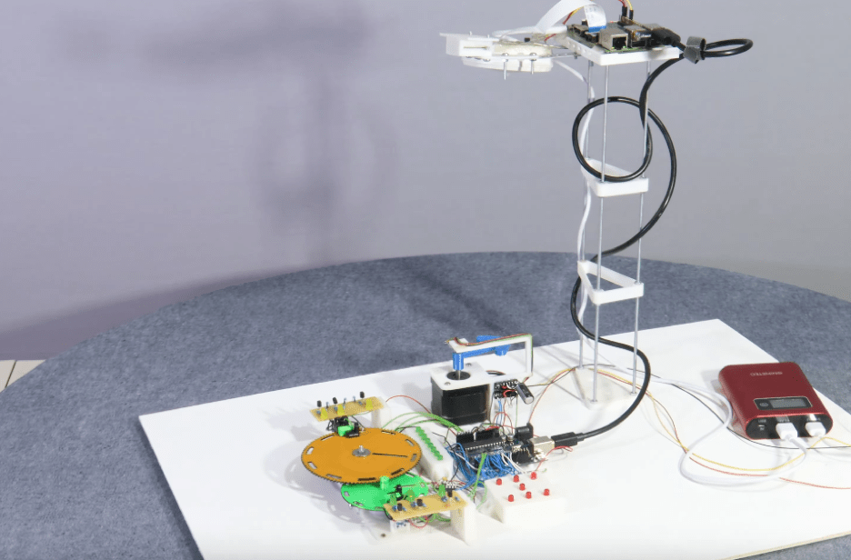
Getting started with physical computing presents a challenge to newcomers, whether due to the cost of acquiring hardware, learning how to manipulate GPIO pins, and being able to easily view what others have done to achieve their results. Norbert Heinz, who runs the site and YouTube channel HomoFaciens, therefore decided to build a system that anyone can control by simply sending an email.
The aptly named “mail2code” project is based around an Arduino Uno Rev3 board, which has been connected to a wide variety of peripherals to help students and hobbyists alike learn different hardware. The setup includes a DC motor attached to a central gear and a faster gear for exploring motors and interrupts, an array of eight LEDs that can act as a binary counter, a die face to explore random numbers, and a stepper motor with an accompanying Hall effect sensor that is used to learn analog signals in response to rotation.
In order to interact with all of this hardware, users are required to submit an email to a mail server hosted on a Raspberry Pi. It, in turn, compiles the C++ code and flashes the Arduino before activating its connected camera and recording what happens next for one minute. Lastly, the code and video clip are uploaded to Heinz’s web server for everyone to view, and an email is also sent to the sender notifying them of their code’s execution.
To view mail2code in more detail, you can watch Heinz’s video below!
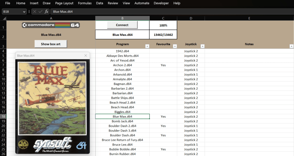
Loading software on a vintage computer, such as a Commodore 64, is a pain. Early eight-bit computers almost never contained any onboard persistent storage, so users had to load software from external media like cassette tapes. To make retro computing far more convenient, RaspberryPioneer developed a method for loading Commodore 64 software from Microsoft Excel.
This workflow starts with a modern computer running Microsoft Excel. RaspberryPioneer created an Excel spreadsheet that acts as a database of Commodore 64 software, linking to the ROMs and containing information such as specific load commands. The spreadsheet integrates Visual Basic for Applications (VBA) programming, so the user can select a software entry and then launch it. Doing so sends that software’s ROM data to the Commodore 64, which loads the software like it came from conventional media.
RaspberryPioneer’s workflow relies on a 5V Arduino board to act as an intermediary between the modern computer and the Commodore 64. The Excel VBA script sends the selected ROM data to the Arduino via a USB serial connection. The Arduino then, in turn, sends the data to the Commodore 64 through a hardware serial connection. That requires a Commodore serial cable, with the standard plug at one end and the other end connected to the Arduino’s pins.
Launched six years ago, Hello World magazine is the education magazine about computing and digital making. It’s made for educators by educators, and a community of teachers around the world reads and contributes to every issue. We’re now starting a monthly Hello World newsletter to bring you more great content for computing educators while you await each new magazine issue.
A monthly newsletter for Hello World readers
The Hello World community is an amazing group of people, and we love hearing your ideas about what could make Hello World even better at supporting your classroom practice. That’s why we host a fun and informative Hello World podcast to chat with educators around the globe about all things computing and digital making, and why we regularly share some of our favourite past magazine articles online to keep the conversation on important topics going.
Now we’re starting a monthly newsletter to offer you another way to get regular computing education ideas and insights you can use in your teaching. Every month, we’ll be curating a couple of interesting Hello World articles, plus news about the free education resources, research, community stories, and events from the Foundation. You can expect bite-size summaries of all items, plus links for you to explore more in your own time.
Sign up today
Keep up with all of the education news from the Raspberry Pi Foundation and Hello World by signing up for the Hello World newsletter today.
If you’re already signed up to the Raspberry Pi LEARN newsletter, then you don’t need to do anything: this newsletter replaces LEARN and you will be automatically subscribed.
We hope you’ll enjoy the first Hello World newsletter, which we will send out this Wednesday. As always, let us know what you think of it on Twitter or Facebook, or here in the comments.
PS Remember that if you work or volunteer as an educator in the UK, you can subscribe to receive free Hello World print copies to your home or workplace.
For fans of Harry Potter, Hogwarts Legacy is a dream game. It drops you into the Potterverse where you can become a wizard, casting spells and riding brooms to your heart’s content. It is a very immersive game, but you lose some of that immersion when you realize you’re actually just pushing buttons on a gamepad. That’s why YouTuber ‘That’s So Mo’ built a custom Hogwarts Legacy controller on a replica Nimbus 2000 broom.
The broom itself is the property of Mo’s friend. It is a very expensive prop replica that looks just like the Nimbus 2000 from the films. Mo couldn’t risk any damage to that, so he attached all of the components to a block of packing foam that can slide on and off the broom handle. Those components include an Arduino, an accelerometer, and an ultrasonic distance sensor.
Thanks to its onboard ATmega32U4 microcontroller, the Arduino is configurable to appear as a USB HID gamepad when connected to a PC. The button presses it sends depend on the orientation of the broom stick and the position of the rider’s body. The accelerometer monitors orientation while the ultrasonic sensor checks the distance to the rider’s torso. So if the rider tucks in close to the Nimbus 2000, the in-game avatar will speed up. If the rider leans right, the avatar will turn right.
With this controller, Mo can play like he’s really riding a broom — at least for as long as his friend lets him borrow the Nimbus 2000!
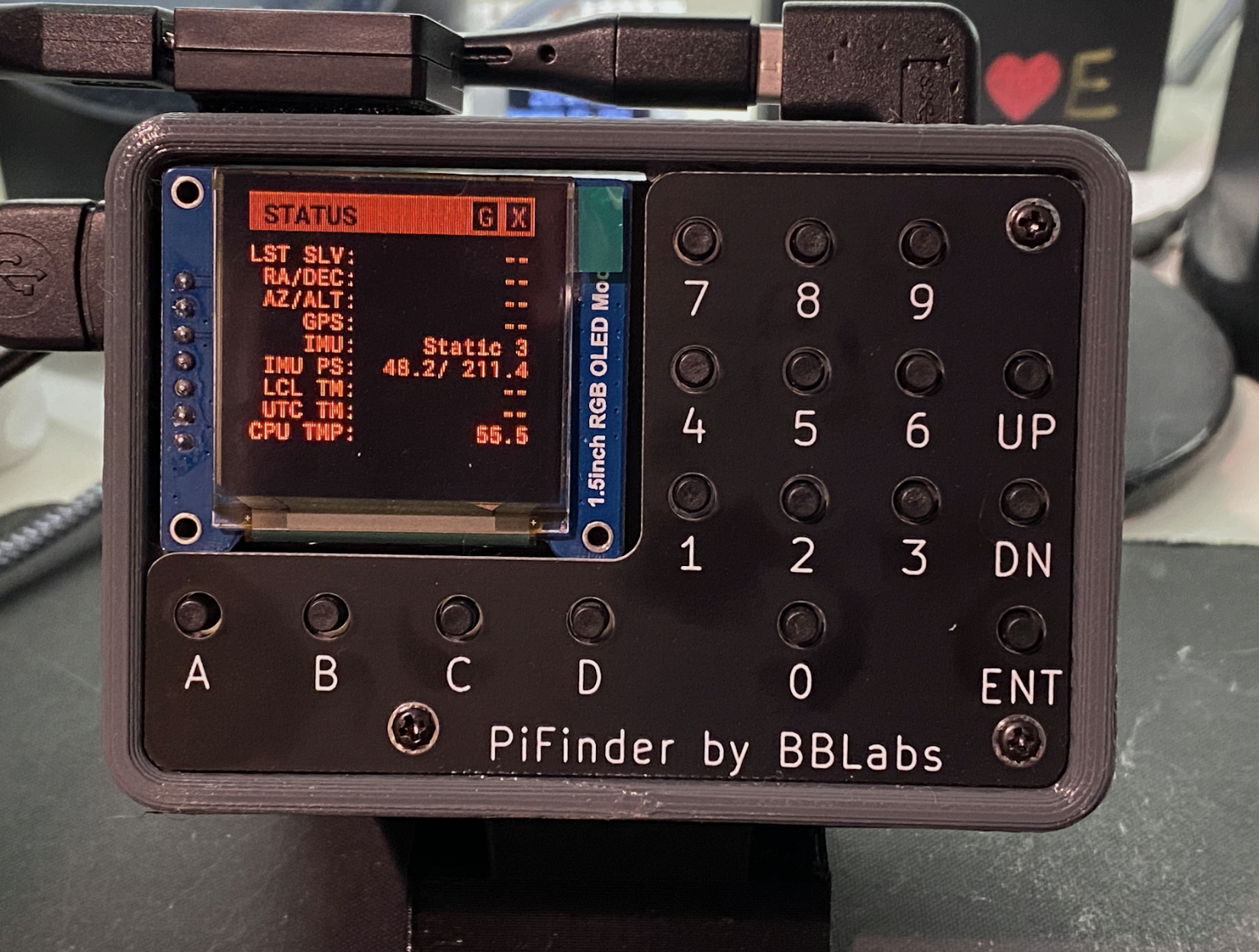
As such, Richard decided to create his own system. “I was seeing articles and forum posts describing electronic finders (devices that use a camera and computer to determine absolute telescope pointing),” he says. “So I decided to see if I could build something I’d be happy using and sharing.”
Scoping the sky
Richard has based his project – called PiFinder – around a Raspberry Pi 4 computer and a Raspberry Pi High Quality Camera, with the idea being to create a device that would take images of the night sky to determine where a telescope is pointing by analysing the pattern of stars.
“I wanted PiFinder to be easily added to any type of telescope, requiring no setup aside from a clear view of the sky to indicate where the telescope is pointing,” Richard says. “I wanted to combine this ability to know where the telescope is pointed with an extensive catalogue of thousands of object locations to help an observer find objects in the sky with simple guidance on which way to push the telescope.” He achieved all of these things and more.
By having the camera constantly taking images, the PiFinder can get to work. “So long as the on-board Inertial Measurement Unit indicates the telescope is static, the camera is snapping images and feeding them to the solving algorithm,” Richard explains. “Depending on sky conditions and which camera is being used, it can take anywhere from 0.25 to 1.5 seconds to capture an exposure which contains enough stars to solve.”
Stars in his eyes
After an image has been taken, it’s processed using code released by the European Space Agency called Tetra3. “It implements a very fast system for extracting stars from an image and using distances between multiple sets of four stats in the image to produce a hash,” Richard says. “This hash can be quickly matched against a pre-computed database of star patterns to find candidate positions. Each potential position is then checked using other stars in the same image to verify the correct solution.”
Extracting stars from the image on a Raspberry Pi 4B computer takes just 100 milliseconds, while solving the image takes 44 ms. “This is all done on a separate thread so the next image can be acquired while the previous image is being solved,” Richard says.
“In practice, this means that the PiFinder can usually achieve one capture/solve per second. If using the Raspberry Pi Global Shutter Camera, it can achieve more than two captures/solves per second due to its much larger pixel size and low-light sensitivity.”
By cycling through several astronomical catalogues and even typing in the ID of a specific celestial body, users can use PiFinder to locate objects in the night sky, receiving simple guidance on which way to push the telescope in order to view them. Richard says it’s working well, which is why he released it to the public after seven months’ work. “I’ll continue to focus on making it as simple to replicate and build as possible as I get more feedback from others,” he reveals.
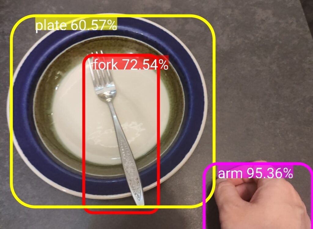
People with visual impairments also enjoy going out to a restaurant for a nice meal, which is why it is common for wait staff to place the salt and pepper shakes in a consistent fashion: salt on the right and pepper on the left. That helps visually impaired diners quickly find the spice they’re looking for and a similar arrangement works for utensils. But what about after the diner sets down a utensil in the middle of a meal? The ForkLocator is an AI system that can help them locate the utensil again.
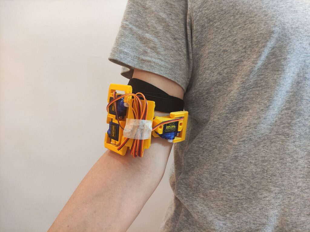
This is a wearable device meant for people with visual impairments. It uses object recognition and haptic cues to help the user locate their fork. The current prototype, built by Revoxdyna, only works with forks. But it would be possible to expand the system to work with the full range of utensils. Haptic cues come from four servo motors, which prod the user’s arm to indicate the direction in which they should move their hand to find the fork.
The user’s smartphone performs the object recognition and should be worn or positioned in such a way that its camera faces the table. The smartphone app looks for the plate, the fork, and the user’s hand. It then calculates a vector from the hand to the fork and tells an Arduino board to actuate the servo motors corresponding to that direction. Those servos and the Arduino attach to a 3D-printed frame that straps to the user’s upper arm.
A lot more development is necessary before a system like the ForkLocator would be ready for the consumer market, but the accessibility benefits are something to applaud.
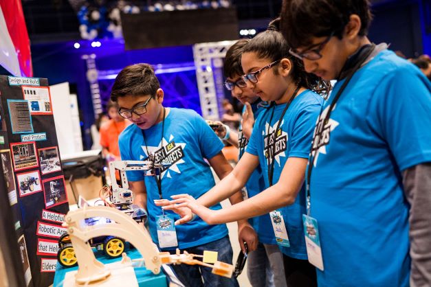
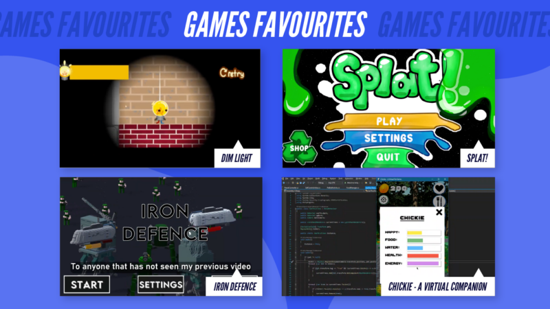
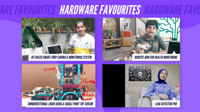
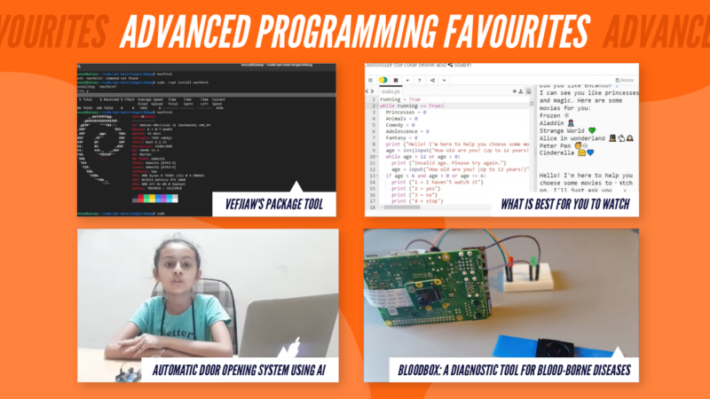
An absolutely huge congratulations to each and every single young creator who participated in Coolest Projects 2023, our digital technology showcase for young people! 5801 young people from 37 countries took part. This year’s participants made projects that entertained, inspired, and wowed us — creators showcased everything from robotic arms to platformer games.
We celebrated every project and maker in a special livestream event this Tuesday:
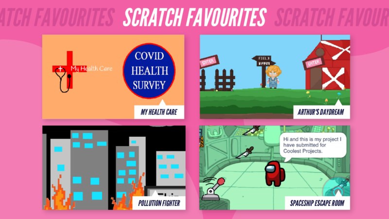
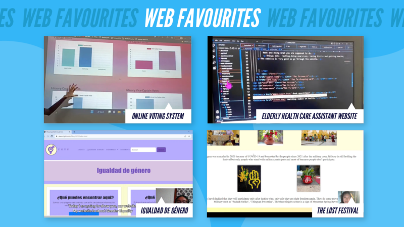
Each year, we invite VIP judges to pick their favourite projects. This year they had the difficult job of choosing between 4111 incredible projects young people showcased. Meet the judges and find out which projects were their favourites.
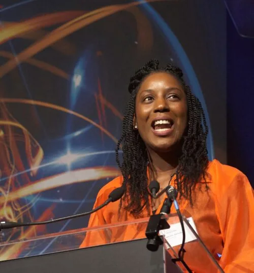
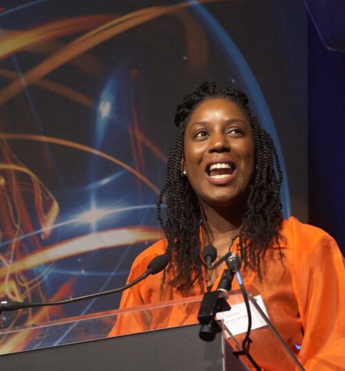
Yewande Akinola’s favourite projects
Yewande is a chartered engineer, innovator, and speaker. She has worked on projects in the UK, Africa, the Middle East, and East Asia, and has been named the UK Young Woman Engineer of the Year by the Institution of Engineering & Technology.
Vaishali is an Indian engineer, innovator, and revolutionary educationist. She is the co-founder of Young Tinker Academy and Young Tinker Foundation, started in 2015 to educate the less-privileged students of rural India. Her team at Young Tinker Foundation has impacted the lives of 150,000+ students.
Lella is an award-winning 18-year-old Digital Changemaker and Power of Youth Champion. Since she taught herself to code at age 8, Lella fosters purpose-driven innovation to create global industry opportunities that ensure young people are at the forefront of the ongoing digital transformation.
Aoife is the Head of Community Development for Meta Data Centres in Europe and Asia. She and her team deliver on Meta’s commitment to playing a positive role and investing in the long-term vitality of Meta Data Centre communities in Ireland, Denmark, Sweden, and Singapore.
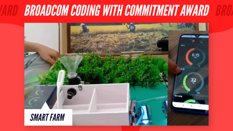
Broadcom Foundation has partnered with us for Coolest Projects to encourage young people who are solving problems that impact their communities. Broadcom Coding with Commitment™ is a special recognition for a Coolest Projects creator aged 11–14 who has learned basic coding as an essential problem-solving tool in STEM and is “thinking globally while acting locally.”
The Broadcom Coding with Commitment™ recognition goes to Smart Farm, a project by Dang, Chi, and An from Vietnam. They designed Smart Farm to help farmers in their community regulate the temperature of animals, feed them on time, and check them for diseases. The team also built a fish pond model that tests the pH of the water and a vegetable garden model that detects when vegetables are wilting, all with the aim of helping local farmers to care for their livestock and protect their livelihoods. Huge congratulations to the team!
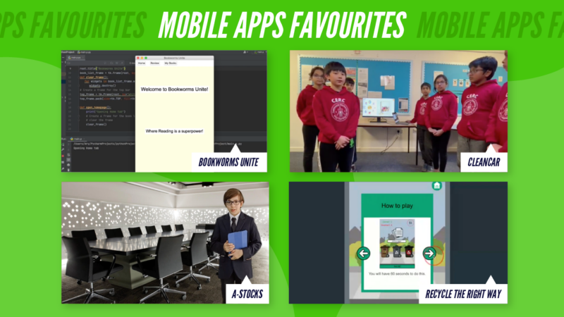
There’s so much more to celebrate
Our judges have chosen their favourite projects — but what about yours? You can explore thousands of incredible projects for 2023 young creators in the Coolest Projects showcase gallery and discover your favourites today.
All young creators who took part will shortly receive their own unique certificate to recognise their amazing achievements. They’ll also be able to log into their Coolest Projects account to find personalised feedback on their projects from our judging team.
Support from our Coolest Projects sponsors means we can make the online showcase and celebration livestream an inspiring experience for the young people taking part. We want to say a big thank you to all of them: Allianz Technologies, Broadcom Foundation, EPAM Systems, Liberty Global, Meta, and Qube Research and Technologies.
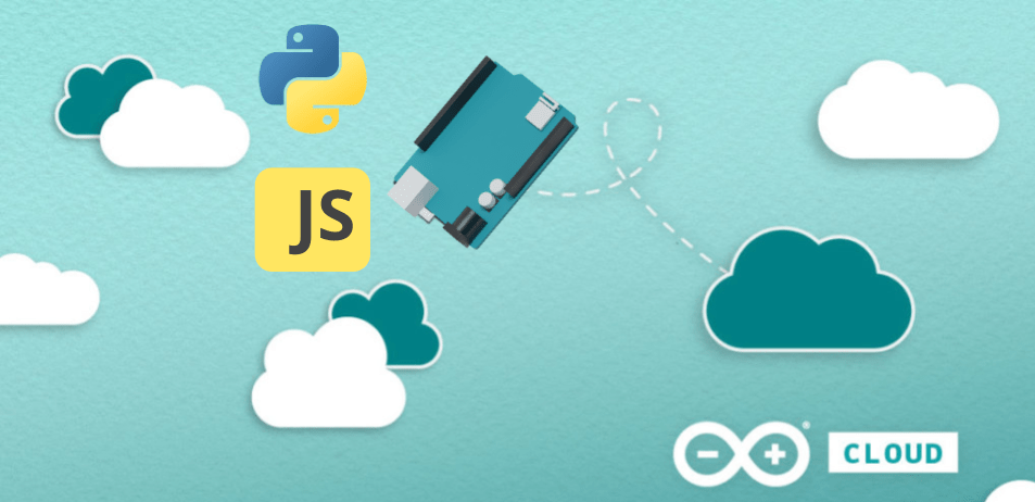
The Internet of Things (IoT) has become a ubiquitous term, encompassing a vast array of applications ranging from small-scale embedded systems to complex networked devices. Traditionally, IoT development has been synonymous with programming in languages like C and C++. However, the landscape is rapidly evolving, with modern languages like Python and JavaScript gaining traction in the IoT space for devices running Linux or other OS, and also with MicroPython for lower resources devices.
In an exciting development, we are thrilled to announce the creation of a workflow on the platform that enables users to seamlessly connect their devices based on these languages with the Arduino Cloud, empowering users to harness their full potential in creating IoT solutions.
The new Manual setup workflow
Traditionally, Arduino Cloud allowed the creation of devices based on Arduino or ESP32/ESP8266 hardware, with automatic sketch creation in C/C++ using the Arduino IoT Cloud library. This workflow featured automatic board provisioning and configuration within the platform. However, we have expanded the device creation process to introduce a new workflow, accommodating applications programmed in Python, MicroPython, or JavaScript, and so offering the ability to create a new breed of applications and devices that can be connected to the Arduino Cloud.
This new workflow, known as “Manual Setup for Any Device” provides users with credentials that can be utilized within their Python, MicroPython, or JavaScript applications. This enables users to keep developing and programming their devices using their preferred environment. Integration with the Arduino Cloud can be achieved using libraries developed in any of the supported languages. Comprehensive documentation, along with a wide array of examples, supports users throughout the implementation process.
By offering this flexible workflow, Arduino Cloud acknowledges the diverse requirements and preferences of developers. Whether you prefer the convenience of automatic provisioning or the flexibility of manual configuration, the choice is now in your hands.
What can you actually do?
Python – The choice for AI
Python is a versatile and widely-used programming language that offers significant benefits for IoT device development. Its simplicity, readability, and extensive library ecosystem make it an ideal choice for both beginners and experienced developers. Python’s vast library ecosystem provides access to a wide range of pre-built modules and functions, allowing developers to leverage existing code and accelerate development. Additionally, Python’s active and supportive community offers a wealth of knowledge and resources, making it easier to troubleshoot issues, seek advice, and learn from others’ experiences.
Python is not only a versatile language for IoT device development but also the de facto standard language and environment for AI programming. Its extensive library ecosystem, including popular libraries such as TensorFlow, PyTorch, and scikit-learn, makes Python the language of choice for implementing machine learning and deep learning algorithms. The availability of these libraries, along with Python’s intuitive syntax and flexibility, enables developers to build and deploy sophisticated AI models and integrate them seamlessly into IoT applications. Python’s dominance in the AI landscape further adds to its value for IoT device development, as it allows developers to leverage AI capabilities and unlock advanced functionalities in their IoT solutions.
Learn more about how to connect your Python applications to the IoT Cloud.
Micropython – The power of Python on tiny processors
MicroPython is a popular platform for IoT development due to its simplicity, efficiency, and versatility. It supports various microcontroller platforms, including Arduino, ESP32, and Raspberry Pi Pico, offering cross-platform compatibility. With its familiar Python syntax, MicroPython is easy to learn and use, making rapid prototyping and development accessible. It optimizes memory usage and runtime performance, even on resource-constrained devices. MicroPython benefits from an extensive library ecosystem, enabling quick integration of functionalities and interoperability with other IoT platforms. Its active community provides abundant resources, support, and a vibrant ecosystem for IoT innovation. Overall, MicroPython is a powerful tool for building efficient and feature-rich IoT devices.
Javascript – Event driven applications across multiple platforms
JavaScript has found its place in IoT device development across various platforms. Node.js, a server-side runtime environment, offers JavaScript’s event-driven and non-blocking nature for efficient handling of IoT tasks. Espruino, a JavaScript platform for microcontrollers, enables direct coding on resource-constrained devices. Johnny-Five, a JavaScript robotics and IoT framework, allows control and interaction with hardware platforms using JavaScript. JavaScript’s versatility, reuse of web development skills, and extensive libraries make it an accessible choice for IoT development. Its event-driven nature aligns well with IoT requirements, and the availability of frameworks and community support fosters rapid development and integration with web-based services.
Check this article to learn more about how to connect your Javascript applications to the IoT Cloud.
But what is Arduino Cloud?
Arduino Cloud is a platform that simplifies the process of developing, deploying, and managing IoT devices. It supports various hardware, including Arduino boards, ESP32, and ESP8266 based boards, and makes it easy for makers, IoT enthusiasts, and professionals to build connected projects without coding expertise. What makes Arduino Cloud stand out is its intuitive interface that abstracts complex tasks, making it accessible to all users. With its low-code approach, based on auto generated code, and the extensive collection of examples and templates, Arduino Cloud offers a simple way for users to get started and enables them to put the focus on their application code.
The platform’s IoT Cloud tool allows for easy management and monitoring of connected devices through customizable dashboards, which provide real-time visualisations of the device’s data. Furthermore, the IoT Cloud can be accessed remotely through the mobile app Arduino IoT Cloud Remote, which is available for both Android and iOS devices, allowing users to manage their devices from anywhere.
As the IoT landscape continues to evolve, Arduino Cloud remains at the forefront, embracing the flexibility and power of Python and JavaScript. We invite you to explore this new feature, unlock your creativity, and share your innovative projects with the Arduino community. Publish your projects on the Arduino Project Hub (PH), where like-minded enthusiasts can discover, learn, and collaborate on IoT solutions that push.
Additionally, engaging in community discussions and project sharing is encouraged in the forum, providing a platform for exchanging ideas, seeking advice, and fostering collaboration among fellow IoT enthusiasts. Together, let’s shape the future of IoT and create a vibrant ecosystem of innovation and knowledge-sharing.
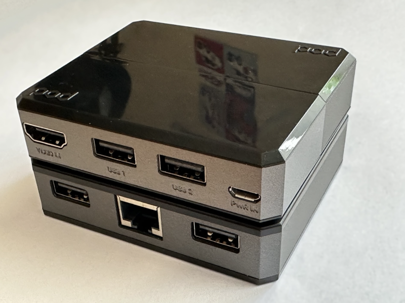
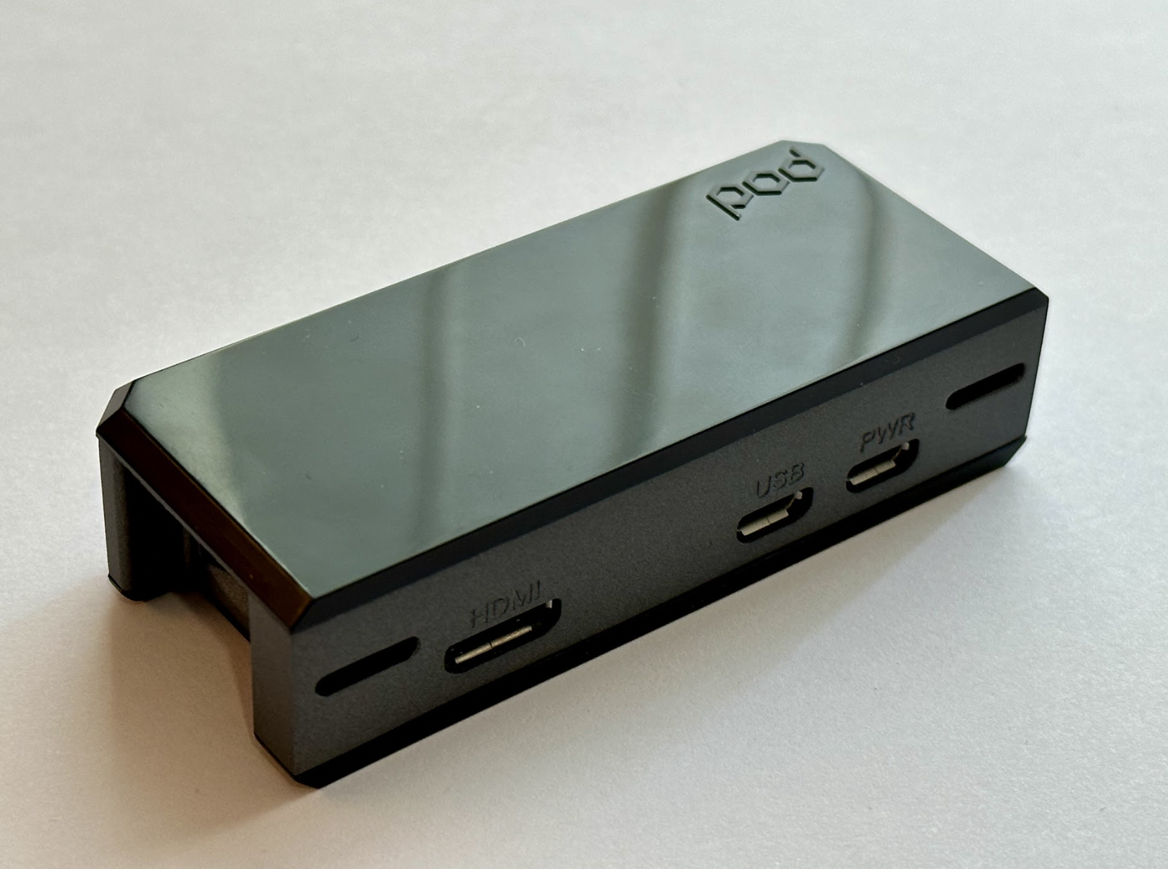
The first add-on module, USB/HDMI (£12/$12), connects directly to mini-HDMI and micro-USB ports, breaking them out into full-sized equivalents and separating the power, freeing up another USB port. Installation is as simple as lining up the connectors and pushing together, with no drivers required. Underneath, a header and power connector are exposed that are used to connect other modules, so you may require this module for compatibility.
But wait, there’s more!
Need some more USB ports? How about Ethernet? The USB/LAN module (£20/$20) does both. A ‘full-size’ module, it sits below our current setup, connecting via an exposed header on the USB/HDMI module. Easily snapping together, you now get an additional four USB connectors (two on the front, two on the back) and an Ethernet connector for hard-wired networking. Again, a one-minute install and Raspberry Pi OS recognises all peripherals without any additional software.
Now it’s show-time. The Display Module (£30/$30) is a 2.8-inch capacitive touchscreen that plugs into Zero’s GPIO. Framed in an attractive black bezel, with four programmable buttons, it transforms Zero into a stand-alone unit opening up the potential for makes. Drivers are required to get the screen running, which we found easy to install. A simple configuration system allows the buttons to be preprogrammed with common functions such as power off or reboot. Provided documentation explains how to take control of them yourself using GPIO. The screen is perfectly adequate, although you’ll need a stylus for meaningful use of the touch capabilities.
All in all, this is a great collection of add-on gadgets for your Zero. The modular nature means you can keep costs (and size) down. Argon has also teased future modules for further expansion. One slight niggle was a lack of access to GPIO and camera connectors, although this can be overcome with USB devices. It would also be interesting if documentation was provided on how you could make your own modules using the through-module header.
Verdict
9/10
Easier GPIO and camera access would be nice, but the exquisite design, tough materials, and sensible pricing more than make up for that. The Argon POD has seriously impressed.
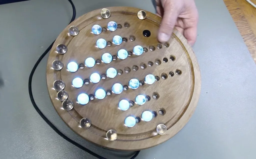
Solitaire is any tabletop game that can be played by just one person, and it can take the form of cards, pegs, memory, and in this case, marbles. As Mark Donners discusses in his element14 Presents video, marble solitaire is made of 33 individual divots and a total of 32 marbles that populate each one except the center with the goal of capturing every marble until the last one lands in the middle. Due to the pattern being somewhat difficult to memorize, Donners constructed a custom board that uses an Arduino Nano and LEDs to light the way.
The board itself was created by first drilling a series of holes into a premade round block of wood before applying a thin layer of paint. Afterwards, he cut a strip of NeoPixel LEDs into three 13-pixel segments and four five-pixel segments before soldering them together in a snaking pattern. The LEDs and an accompanying button were then connected to the Nano, which would be responsible for controlling the board.
Donners programmed his solitaire board by first defining it as an array of LED positions and a list of moves which get illuminated on the NeoPixels below and between the marbles until the game has been solved. Once the player gets the final marble to the center, a small rainbow animation plays with the option of starting over to play again. To see this board in action, be sure to watch Donners’ video below!
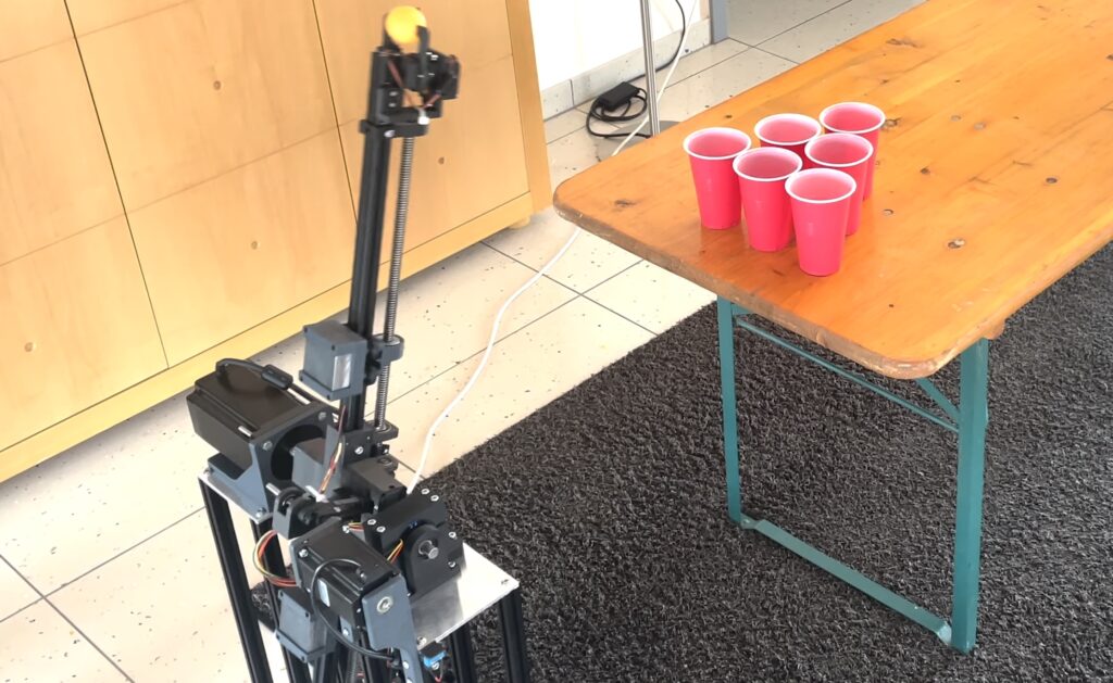
Beer pong is a classic party game involving skill, persistence, and alcohol tolerance. Participating in friendly games of beer pong is a great way to socialize with peers, but what if you aren’t very good at tossing ping pong balls into red Solo cups? In that case, you may want to follow the lead of Niklas Bommersbach to construct a robot that can play beer pong for you.
This robot works a bit like a medieval catapult to launch ping pong balls, but that’s more complicated than it sounds. The target (a cup) is quite small, which means the robot has to be accurate. Like a bullet traveling along a ballistic trajectory, the ping pong ball will experience both gravity and drag from air resistance. The robot has to take those into account, as well as vibrations in the catapult arm that cause oscillations to throw off the throw. Bommersbach had to implement algorithms to take those into account, going so far as to measure the movement with an IMU.
The robot is a combination of aluminum extrusion and 3D-printed parts. An Arduino Uno Rev3 board controls two continuous rotation servo motors that start the arm spinning, then a third stepper opens the gripper to release the ball at the proper time. There is also a vibration-dampening system that uses a complex system of lead screws and gears to move weights up and down the arm to alter the frequency at which the arm structure oscillates, ensuring that those do not interfere with a throw at a specific distance.
There isn’t any computer vision, so Bommersbach has to enter the parameters for each shot. But the result is still impressive and this robot is more consistent than most experienced players.
There are few feelings more satisfying than building your own home office or gaming setup from scratch. Sitting at your workstation knowing that everything is made just the way you like it, in exactly the way you imagined — it’s pretty neat.
Today, it’s easier than ever to craft your own equipment by hand, at home. Tools like Arduino make it possible to build sophisticated, high-tech devices that sometimes work even better than anything you can find in a store.
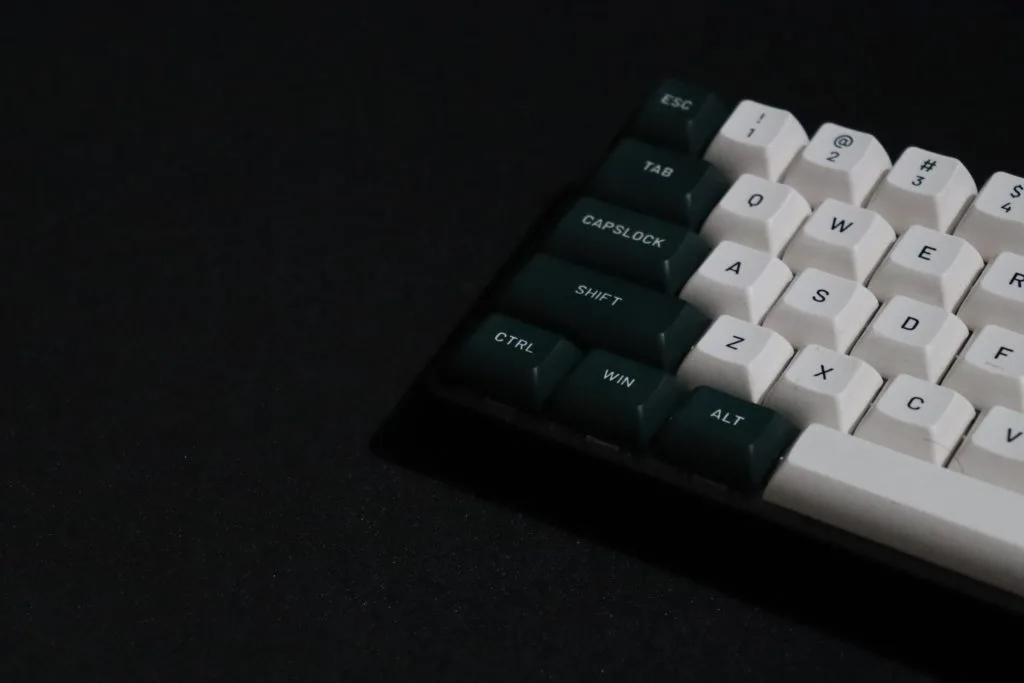
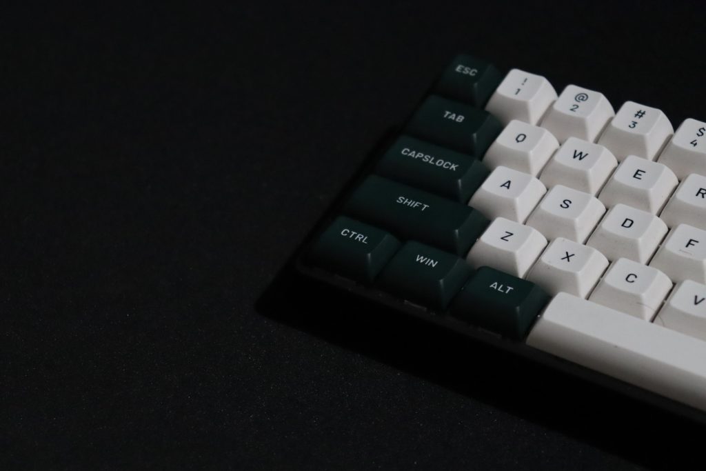
In this article, we’ll focus on keyboards — specifically, wireless hand-wired keyboards. We’ll show you what they are, what you need to get started, and how Arduino users have tackled the challenge of designing their own.
What is a hand-wired keyboard?
Most store-bought keyboards use something called a PCB, or printed circuit board. A PCB is used to connect the different electronic components inside the keyboard to one another.
In a hand-wired keyboard, there is no PCB. Instead, the components are connected by wires, by hand. This way, you have complete control over how your keyboard is designed, allowing you to assemble a keyboard that looks, feels, and works exactly how you want it to.
Why should you make a hand-wired keyboard?
We all know the feeling of using a keyboard that doesn’t feel quite right. And if you work from a desk, spend a lot of time gaming, or just enjoy hammering away at a keyboard for any other reason, having the right setup makes all the difference.
Taking a DIY approach gives you the control and freedom to devise a hand-wired keyboard that is just right for you, your needs, your preferences, and your aesthetic. Not to mention, it’s a ton of fun!
What you need to get started
Building your own hand-wired keyboard doesn’t require a huge amount of resources or materials, and it can be done fairly cheaply with a bit of prior research and preparation. Here are the main components you’ll need:
A switch plate to give the keyboard structure and support your keys
Switches (enough for each keycap)
Solder wire and electrical wire
A 1N4148 diode for each switch
Wire to connect the rows and columns to the controller
Spacers and screws
Solder and a soldering iron kit
Make your own hand-wired keyboards with Arduino
When it comes to building your own keyboard with Arduino, you don’t need to look any further than Joe Scotto. Over the last several months, Scotto has mastered the art of building hand-wired keyboards, amassing an impressive collection of creations, and now he’s sharing his expertise with the world.
Scotto says, “Something about handwriting just hits different, it feels like I actually built the board… if that makes sense.”
On top of sharing his work on Reddit, Scotto also has a YouTube channel where he goes into depth about how to construct hand-wired keyboards, some of the main challenges involved, what you need to get started, and more.
Let’s run through a few tips to be aware of when creating your keyboard, so you can avoid mistakes and get the most out of the experience.
Know what size you want in advance. Keyboards come in a range of sizes and each one has its own pros and cons. For example, gamers tend to prefer smaller keyboards in a 60% of 65% layout, whereas for office use you might want something bigger like a TKL.
Be careful with soldering. Solder can produce dangerous fumes, so make sure you do this part of the process in a well-ventilated area and take precautions.
Don’t worry about making mistakes, embrace them! It’s unlikely that your very first attempt at a hand-wired keyboard will be perfect. That’s fine — it’s an opportunity to tweak, improve, and learn.
Consider adding in some neat extra features like a reset switch. You can also experiment with “split keyboards” where each side is distinct from the other.
A well-made, hand-wired keyboard is an impressive piece of hardware. Don’t forget to post your results online and share with the Arduino community!
Get creative with Arduino
Hand-wired keyboards are just one example of the many things you can make in your very own home using Arduino and a few other components. The Arduino Project Hub is full of other examples and in-depth guides from the community members to inspire and inform your next project.
Visit our home page to learn more about Arduino and find out how to get started with your own projects.
It reminds me that each country, and often each region within a country, had its own computing startups, and their products reflected the unique cultural and technological idiosyncrasies of the time and place.
Around the world
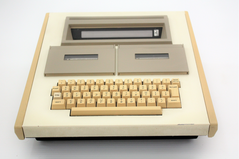
The MCM/70, produced by the Canadian company Micro Computer Machines, holds a special place in the annals of computing history as one of the first, if not the first, personal computers. Introduced in 1973, it boasted an Intel 8008 processor, 4KB of RAM, and an APL (A Programming Language) operating system: another thing I’ve never heard of before.
The MCM/70’s unique design, including a twin cassette deck and a built-in segmented LED display, reminds me of a modern cyberdeck.
It’s a pleasure to see a reproduction of this iconic machine today.
In the US, the Apple II was a revelation when it was launched in 1977. It was the first computer many Americans ever saw (here in the UK, mine was a Dragon 32). The Apple II’s role in popularizing the concept of the personal computer cannot be overstated.
I preferred the Commodore 64, with its powerful multimedia capabilities. It became a beloved home computer, and also a favourite platform for game developers. It’s still my favourite.
Moving to the UK, the ZX Spectrum and the BBC Micro were pivotal in the country’s computing history. I had a ZX Spectrum, and despite its rubbery keyboard and modest specifications, it was a revolution in the home computing market due to its affordability. The BBC Micro, on the other hand, was a staple in schools, providing many British children with their first taste of computing. Over in Japan, the NEC PC-8801 and Sharp X1 series were leading the pack. I don’t think I ever saw one until visiting computing museums as an adult. Down under, the Microbee, an Australian-built computer, had a cult following. In the Soviet Union, locally produced machines like the Agat and the Electronika BK series were reverse-engineered Western designs.
Today, the world of computing can seem homogenous, dominated by a few large corporations. A MacBook is a MacBook all over the world. We use devices with eerily similar designs and identical operating systems. But in the 1980s, computers were wonderfully diverse. They were local, they were personal.
One of the most fascinating aspects of the Raspberry Pi is its ability to emulate retro computers. This enables enthusiasts to experience the computing past first hand, and younger generations to discover the rich history of personal computing.
Cycling is a great way to spend time outdoors while simultaneously getting exercise and even as a mode of efficient transportation. And in the last few years due to the recent proliferation of e-bikes on the market and the pandemic, there has been an explosion in the number of people wanting to use bikes on a regular basis. A few people have gone a step further and have taken it upon themselves to create devices that make this experience safer, more convenient, or more fun. For this year’s World Bicycle Day, let’s celebrate these makers and how they were able to creatively embed Arduino products into their designs for a better cycling experience.
Automatic shifter
The purpose of a transmission is to convert the rotation of the motor into torque for the wheels, with more being needed at lower speeds for acceleration and less when cruising. Similarly, most bikes also have gearing wherein the rider can downshift to get up a hill or upshift to make larger strides on a straightaway. Jan Oelbrandt’s Shift4Me project eliminates the need to consciously think about this since it uses a magnetic cadence sensor attached to an Arduino Nano which allows it to automatically shift up or down depending on how quickly the pedals are moving.
Similar to how a persistence of vision (POV) display moves rapidly changing pixels through the air to produce the illusion of a larger image, maker Sagarrabanana devised a towable bike trailer that sprays water on the ground using seven individual jets which take the place of the pixels in a POV display. Controlled by an Arduino Nano, the jets’ timing is determined by the bike’s speed in order to precisely deposit even lines of water in a dot-matrix pattern. Text from the user is inputted on a mobile phone and sent to the Nano via an HC-05 Bluetooth® module for printing.
Biking position sensing
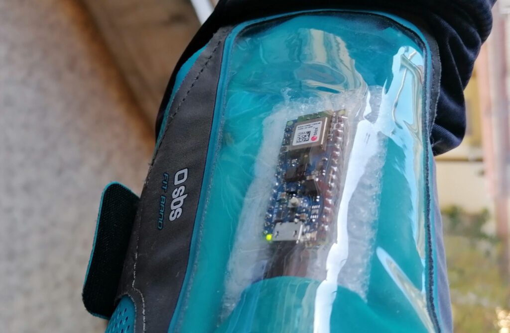
Bike computers are great for collecting detailed information on speed, cadence, power output, elevation, and more, but none can say whether the cyclist was sitting or standing for a period of time. This is why Fabio Antonini used an Arduino Nano 33 BLE Sense and Edge Impulse to develop such a device. He started by gathering 20 minutes of him sitting on a plane, sitting while going uphill, jumping on the pedals going uphill, and pushing on a flat sprint, then after training, deployed it to the Nano. In order to tell what is being detected, the built-in RGB LED changes color to notify the user.
An unusual two-wheel steering system
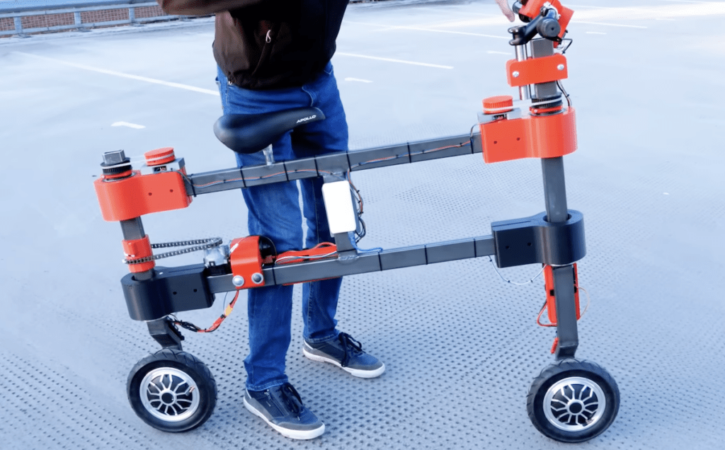
Prolific YouTuber and maker James Bruton is no stranger to unique robots and vehicles, and his take on the bicycle is no different. Unlike a traditional design that has a free front wheel and a locked rear wheel, this e-bike has a hub motor in both wheels that can turn independently thanks to an additional pair of motors. When the rider turns the front wheel, an Arduino Uno reads the encoder value and uses it to spin the rear wheel according to one of three modes: lock, mimic the front, and mirror the front. And although the resulting creating isn’t too practical, it’s a great way to see what’s possible when thinking out of the box.
Intelligent lock
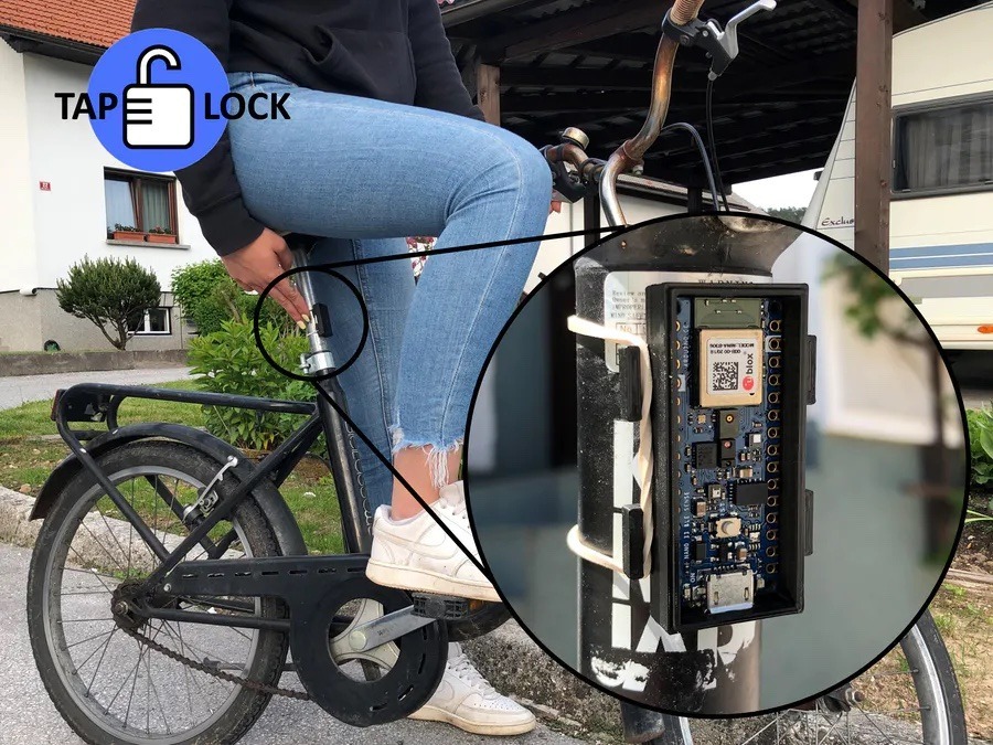
Nearly every bike lock in existence is operated by inserting a key into a cylinder and turning it to release the secured frame and/or wheel from a post. While this approach works, it also lacks several useful features such as keyless entry, mobile connectivity, and location tracking. The TapLock project reinvents the lock by relying on either a series of physical taps on the lock’s enclosure in a certain pattern or a paired phone to unlock. Beyond this, the TapLock’s Arduino Nano 33 BLE Sense communicates with the mobile app to store the current location on a map and even remotely lock the bike.
Compact turn signals
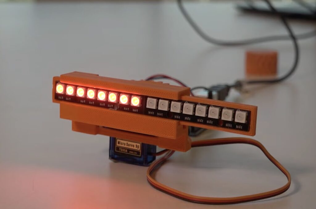
In a car, signaling is as easy as pushing a stock up or down to indicate your intention of changing lanes or turning, but for bikes, this role falls to the rider having to move their arm around. Tom Ouwerkerk’s solution was to buld a very compact signal by combing two eight-LED NeoPixel strips and an Arduino Uno to act as the signal. The strips sit on a gliding mechanism which moves either left or right thanks to a servo motor underneath, and it helps to clarify the intended direction of travel even further.
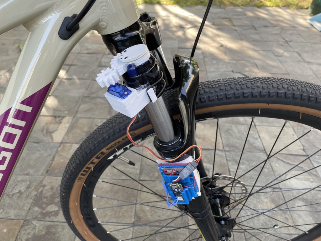
ML-powered adjustable suspension
Higher-end, modern cars are beginning to add automatically adjustable suspension systems to their drivetrains which help to adapt the car to the current terrain, atmospheric conditions, and the driver’s comfort level. Jallson Suryo was able to create his own thanks to an Arduino Nano 33 BLE Sense and a servo motor that turns the bike’s front suspension fork to increase or decrease stiffness. Terrain recognition was accomplished by training an edge ML model on IMU readings and using them to distinguish between idle, smooth, medium, rough, and sprint conditions.
Connecting a stationary bike to a simulator
Bicycling simulators are a great way to experience races against others, explore trails, or simply enjoy a pleasant ride no matter what the weather outside is. Zwift is one such software, and two important features are that your actual pedaling speed is matched in-game and the game controls the pedaling difficulty. Gene’s Green Machine was able to integrate his bike with the system by connecting an Arduino Nano 33 IoT board to a DPS5020 charge controller for reading the current wattage and setting the target resistance. All of this information is sent and received by utilizing the Nano’s capabilities.
Similar to the previous project, video game creator Jelle Vermandere wanted to ride his bike indoors along a virtual track. But this time, he took it a step further by not only integrating his bike using an Arduino Uno which determines the wheel speed via a magnetic reed switch, but building the game himself in Unity. He had to construct and animate models for himself, the bike, and the scenery. After adding an AI and ranking system to the game, he was able to successfully race within the virtual environment on a real bike.
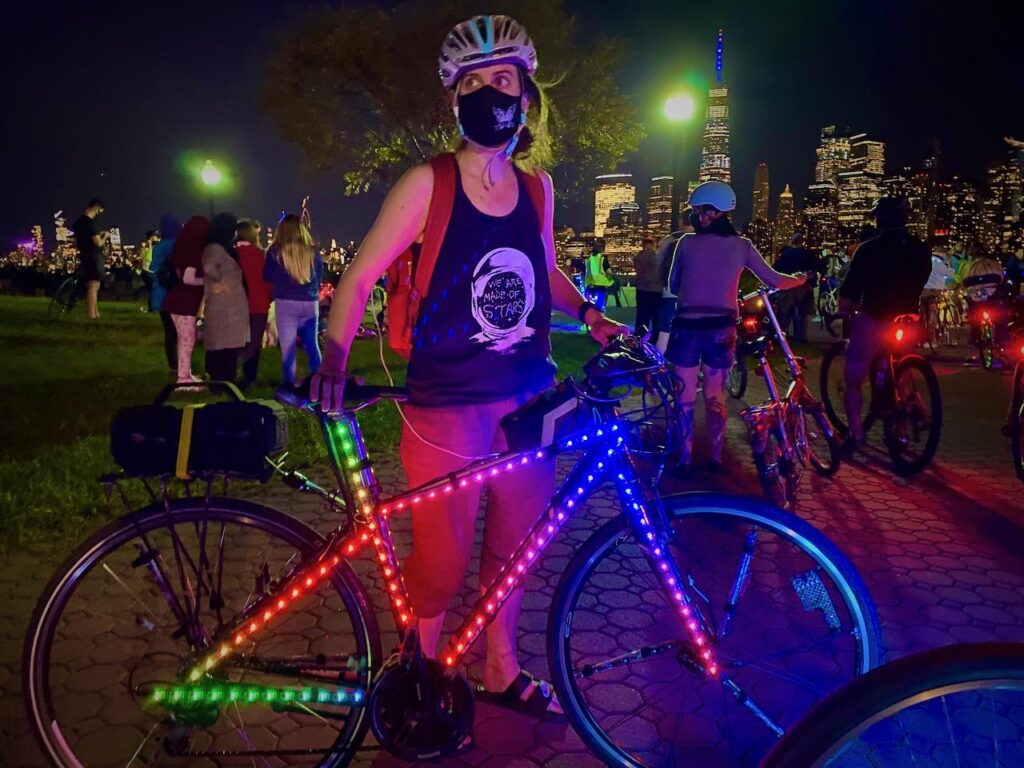
Responsive LED system
Motivated by the desire for a more advanced lighting system while on her nighttime bike rides, Natasha (TechnoChic) decided to affix strips of NeoPixel LEDs all over her bike that could react to music in real-time. The LEDs are controlled by an Arduino Nano 33 IoT that is, in turn, connected to her boombox via a 3.5mm audio jack for reading the audio signal. Two additional Nano 33 IoT boards were used for the wheels, along with more NeoPixels and batteries for each.
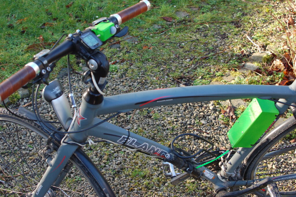
GPS tracker
Bicycle theft has been rapidly increasing over the last couple of years, which is why being able to recover a stolen bike has become vital. Johan’s bike tracker project contains an Arduino MKR GSM 1400 which reads motion data from an IMU and uses it to determine if the bike has moved when it is not supposed to. Once movement is detected, the board reads GPS data from a MKR GPS Shield and sends it over an LTE data connection in real-time so that the bike can be found.
The majority of mountain bikes lack useful safety features such as integrated lights, turn signals, and speed tracking, which is why Collin Wentzien embarked on his “(not so) electric bike” project. He built a series of features, including automatic brake/turn lights, a headlight, and an electronic horn with the goal of improving safety. Furthermore, his bike also got a bike computer upgrade which contains an Arduino Mega, GPS module, and dual screens for displaying relevant telemetry data.
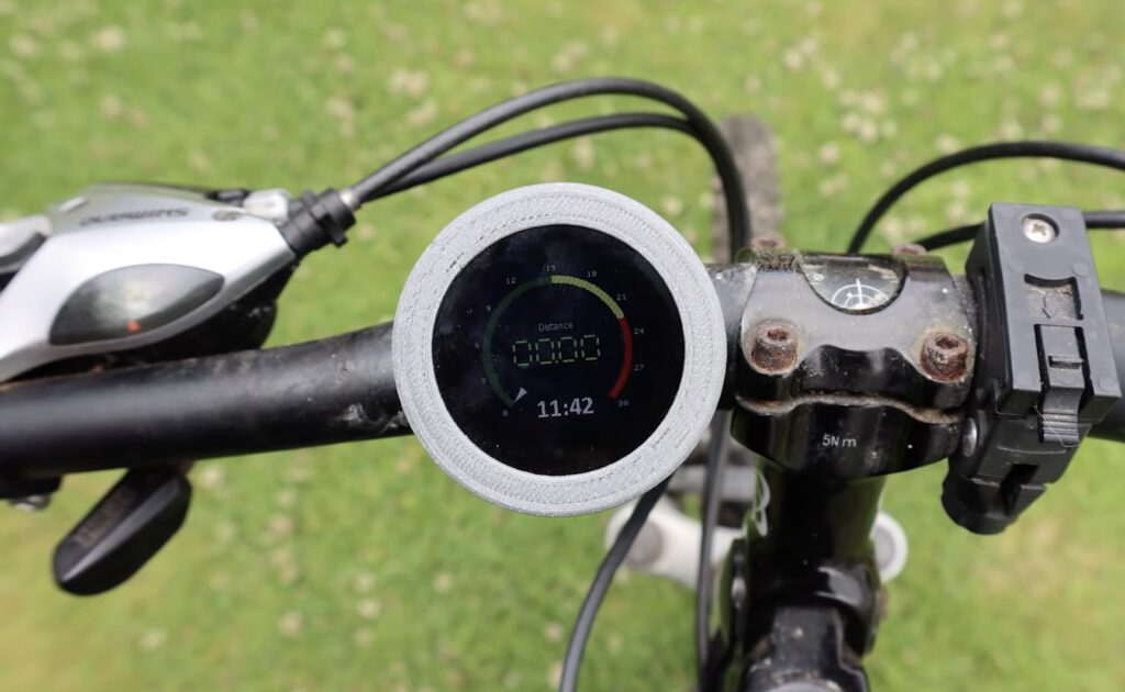
Speedometer display
After losing the display unit for her bike computer, Element14 Presents host Katie wanted to replace it with a DIY version that tracked the current speed via GPS instead of wheel rotations. An Arduino Nano 33 IoT board handled communication between the small 1.3” LCD screen and one of Quectel’s L80 small form-factor GPS modules. On each loop of the program, the time, speed, and distance are all shown on the screen thanks to the 4D Systems genieArduino display library.
This last DIY bicycle computer was made by YouTuber cubicpixelDE, and it integrates an Arduino Nano 33 BLE Sense along with a myriad of bicycle sensors and a heart rate sensor over BLE to display valuable data to the rider. The entire system combines a 1.8” color TFT screen and the Nano 33 BLE Sense into a single, compact unit which fits alongside the handlebar and reads out data to a mobile app wirelessly.
Um dir ein optimales Erlebnis zu bieten, verwenden wir Technologien wie Cookies, um Geräteinformationen zu speichern und/oder darauf zuzugreifen. Wenn du diesen Technologien zustimmst, können wir Daten wie das Surfverhalten oder eindeutige IDs auf dieser Website verarbeiten. Wenn du deine Einwillligung nicht erteilst oder zurückziehst, können bestimmte Merkmale und Funktionen beeinträchtigt werden.
Funktional
Immer aktiv
Die technische Speicherung oder der Zugang ist unbedingt erforderlich für den rechtmäßigen Zweck, die Nutzung eines bestimmten Dienstes zu ermöglichen, der vom Teilnehmer oder Nutzer ausdrücklich gewünscht wird, oder für den alleinigen Zweck, die Übertragung einer Nachricht über ein elektronisches Kommunikationsnetz durchzuführen.
Vorlieben
Die technische Speicherung oder der Zugriff ist für den rechtmäßigen Zweck der Speicherung von Präferenzen erforderlich, die nicht vom Abonnenten oder Benutzer angefordert wurden.
Statistiken
Die technische Speicherung oder der Zugriff, der ausschließlich zu statistischen Zwecken erfolgt.Die technische Speicherung oder der Zugriff, der ausschließlich zu anonymen statistischen Zwecken verwendet wird. Ohne eine Vorladung, die freiwillige Zustimmung deines Internetdienstanbieters oder zusätzliche Aufzeichnungen von Dritten können die zu diesem Zweck gespeicherten oder abgerufenen Informationen allein in der Regel nicht dazu verwendet werden, dich zu identifizieren.
Marketing
Die technische Speicherung oder der Zugriff ist erforderlich, um Nutzerprofile zu erstellen, um Werbung zu versenden oder um den Nutzer auf einer Website oder über mehrere Websites hinweg zu ähnlichen Marketingzwecken zu verfolgen.


 and the board, in turn, would begin charging a pair of supercapacitors via a series of MOSFETs, relays, and op-amps until they each reached about 8V. Once everything had been tested on a breadboard, Rasic soldered his components onto perfboard and arranged them inside a custom weatherproof case.