Kategorie: Linux

  • Technaxx TX-207 solar charging case review

    Technaxx TX-207 solar charging case review

    Reading Time: 2 minutes

    Unfolding the case reveals three solar panels that output 6 V with 3 A (max 21 W) of power. Enough to power a Raspberry Pi Zero or Pico device. We set it up with a Raspberry Pi Zero 2 W in the pocket to test performance. We used a modified version of jbudd’s uptime.sh code to log the uptime (see this Raspberry Pi forum post). Our Zero 2 W was connected to the local Wi-Fi network so we could log in and check the uptime.log file throughout the test. Our first test involved popping a Zero 2 W directly to the USB-A slot in the TX-207 and we hung the charger vertical in a south-facing window. In theory, this sounded good but the TX-207 powered Raspberry Pi Zero 2 W for less than a minute in a whole day. After that, we took it outside and laid it out flat in a garden where it would sporadically power, sometimes for up to six minutes, but our Zero 2 W  would frequently drop out along with the sun. Pairing the TX-207 with a USB battery charger was a game-changer. We coupled it up with a Golf GF-017 2600 mAh battery charger, which held the charge provided by the TX-207 and charged up the battery alongside running Zero 2 W. We started with a completely empty battery charger and our Raspberry Pi Zero 2 W ran up the charge and went for a total of 13 hours and 14 minutes with no downtime.

    The TX-207 provides a constant drip of power in a well-designed portable case

    So, paired with a suitable battery, you can expect a day’s worth of power from this. More than enough to run scripts and handle low-voltage sensor HATs and other hardware.

    It’s not listed as waterproof, although it did tip it down one day to no discernible effect. It certainly feels sturdy enough to withstand the elements, as long as you keep an eye on things.

    You need to pair it with a USB charger for it to be of any real use

    Verdict

    8/10

    An exciting device to pair with Raspberry Pi Zero 2 W. You’ll need a battery pack for it to work reliably.

    Specs

    Power: Max power 21 W, Max voltage 6 V, Current 3 A Max, Efficiency >19%

    Dimensions: Weight: 0.75 kg Dimensions: 20 (81 unfolded) × 29 × 3 cm

    Design: Solar panel – monocrystalline solar cell, Operating temperature +10°C~+40°C, Material PET, Plug type 2 × USB-A (3 A max)

  • Helping robot dogs feel through their paws

    Helping robot dogs feel through their paws

    Reading Time: 2 minutes

    Your dog has nerve endings covering its entire body, giving it a sense of touch. It can feel the ground through its paws and use that information to gain better traction or detect harmful terrain. For robots to perform as well as their biological counterparts, they need a similar level of sensory input. In pursuit of that goal, the Autonomous Robots Lab designed TRACEPaw for legged robots.

    TRACEPaw (Terrain Recognition And Contact force Estimation Paw) is a sensorized foot for robot dogs that includes all of the hardware necessary to calculate force and classify terrain. Most systems like this use direct sensor readings, such as those from force sensors. But TRACEPaw is unique in that it uses indirect data to infer this information. The actual foot is a deformable silicone hemisphere. A camera looks at that and calculates the force based on the deformation it sees. In a similar way, a microphone listens to the sound of contact and uses that to judge the type of terrain, like gravel or dirt.

    To keep TRACEPaw self-contained, Autonomous Robots Lab chose to utilize an Arduino Nicla Vision board. That has an integrated camera, microphone, six-axis motion sensor, and enough processing power for onboard machine learning. Using OpenMV and TensorFlow Lite, TRACEPaw can estimate the force on the silicone pad based on how much it deforms during a step. It can also analyze the audio signal from the microphone to guess the terrain, as the silicone pad sounds different when touching asphalt than it does when touching loose soil.

    More details on the project are available on GitHub.

    The post Helping robot dogs feel through their paws appeared first on Arduino Blog.

    Website: LINK

  • DIY parachute system saves drones and rockets

    DIY parachute system saves drones and rockets

    Reading Time: 2 minutes

    Today’s consumer and professional drones are very stable. They’re easy to pilot and we’re past the era of rampant out-of-control drone crashes. But drones can still fail and benefit from a system that lets them return safely to the ground without damage. That is also true for hobby rockets, which still have very experimental controlled descent systems. To suit both types of craft, Niklas Bommersbach designed his own setup to detect critical flight behavior and then activate a two-stage parachute.

    The idea is something familiar to everyone: if the aerial vehicle experiences uncontrolled descent, the parachute deploys and returns it gently to the ground for recovery. But achieving that is more difficult than you might think. Bommersbach had to engineer a robust deployment mechanism, as well as a system to trigger the deployment. He chose to load the primary parachute with a spring mechanism, plus a drogue chute as a backup. That drogue chute would also slow descent if the primary parachute fails to deploy altogether.

    An Arduino Nano Every board monitors altitude using a barometric pressure sensor. It can either deploy the parachute at a set altitude when it senses rapid descent indicative of an uncontrolled fall, or it can respond to a manual command sent via radio. The chutes reside within 3D-printed containers opened servo motors. Power comes from a small lithium battery independent of the craft’s battery, so the system is self-contained. The Arduino first deploys the drogue chute, which slows descent and tries to pull out the main chute. If that fails, the Arduino can actively deploy the main chute.

    [youtube https://www.youtube.com/watch?v=5JmrC4AGryo?feature=oembed&w=500&h=281]

    This redundant and self-contained parachute system should be reliable and affordable, making it suitable for drones and experimental rockets.

    The post DIY parachute system saves drones and rockets appeared first on Arduino Blog.

    Website: LINK

  • Arduino-powered pickpocket trap catches thieves red-handed

    Arduino-powered pickpocket trap catches thieves red-handed

    Reading Time: 2 minutes

    People living in small towns and rural areas may not realize it, but pickpocketing is a genuine issue in big cities. Real-life pickpockets aren’t magic like those in movies, but they can pull an item like a wallet from your pocket without you noticing — it is surprisingly easy to do. The only reliable way to prevent that is to make sure nothing valuable is easily accessible. But Engineering Dads didn’t want to protect their belongings, they wanted to catch pickpockets red-handed.

    If a pickpocket does their job well, you won’t notice your missing wallet until later when you go to pay for something. So this device needed to trigger the moment it leaves a pocket and to let everyone in the vicinity know about it. To achieve that, it needed a sensor to detect the theft (but not normal movement) and it needed a way to alert the owner — and, ideally, everyone else in the area.

    In this case, the sensor is a photoresistor. An Arduino Nano monitors that photoresistor and expects to see darkness most of the time, because the gadget should be in a pocket. If it registers significant light, that indicates that the unit is no longer in a pocket and has therefore been stolen. When that occurs, it starts blaring the famous “Attenzione Pickpocket!” viral video audio through a speaker module. Engineering Dads doesn’t say what kind of module that is, but there are a number of suitable options. The hardware fits inside a 3D-printed enclosure that is close enough to the size of a wallet to fool some thieves.

    [youtube https://www.youtube.com/watch?v=xcigUF8nSfM?feature=oembed&w=500&h=281]

    The post Arduino-powered pickpocket trap catches thieves red-handed appeared first on Arduino Blog.

    Website: LINK

  • Testing fast charging damage to smartphone batteries

    Testing fast charging damage to smartphone batteries

    Reading Time: 2 minutes

    Most people leave their phones on their chargers overnight, but sometimes you end up at 5% halfway through the day and need to top off your battery. Fast charging is very convenient in such circumstances, but it may be damaging your smartphone’s battery and reducing its capacity over time. To find out if that does happen, GreatScott! used Arduino to test fast charging on several smartphone batteries.

    Lithium batteries aren’t susceptible to the same degradation issues that were common for NiCad batteries, but that doesn’t mean they are impervious to damage. GreatScott! suspected that fast charging stresses Li-Ion batteries and diminishes their capacity. To test that idea, he needed to put batteries through many charge and discharge cycles. For this experiment, he had a control group charging with the typical 1A of current and another group fast charging at 5A. Both groups discharged at a constant 1A and went through 100 cycles.

    Charging and discharging six batteries 100 times each is a time-consuming task, so GreatScott! designed custom devices for the job. Each is a custom PCB populated with an Arduino Nano board, an OLED screen, lithium charging circuitry, and the discharge circuit. That discharge circuit utilizes an op-amp to convert a constant 1A into waste heat. The OLED shows the battery voltage at any given time and the number of charge cycles.

    These test devices let GreatScott! gather valuable data. The batteries charged at 1A didn’t suffer any substantial capacity loss, but the batteries charged at 5A lost an average of 1.6% of their capacity. That was after only 100 cycles, so the loss would get much worse over the course of years. GreatScott! concluded that it is best to avoid fast charging and to only use it when necessary.

    [youtube https://www.youtube.com/watch?v=iMn2yVoEqPs?feature=oembed&w=500&h=281]

    The post Testing fast charging damage to smartphone batteries appeared first on Arduino Blog.

    Website: LINK

  • Make a Pico LCD true or false quiz game

    Make a Pico LCD true or false quiz game

    Reading Time: 6 minutes

    01. LCD character display

    This project is based around an LCD display. Our display has 16 characters across two lines and is often referenced as a ‘1602’. These usually contain an HD44780, or equivalent, driver chip that displays the appropriate pixels that make up the characters.

    One downside of the display is that the driver chip needs at least six data connections. This uses up GPIO ports, as well as needing lots of wires to the LCD display. A common solution is to have a ‘backpack’ fitted to the rear of the LCD display using a port expander. The example used here is a PCF8574T 8-bit port expander.

    Figure 1: Wiring diagram for Raspberry Pi Pico, voltage level shifter, and LCD display

    02. Designed for 5 V

    The port expanders are available on a PCB backpack pre-soldered onto the back of the LCD PCB. This saves you from having to create your own circuit, but it does come with an issue. These circuits are normally designed for 5 V, whereas a Pico uses 3.3 V for the GPIO ports.

    Connecting a 5 V signal to a Pico GPIO port could cause permanent damage to the latter, so this tutorial looks at some of the possible solutions to interfacing between devices designed for different voltages.

    03. Move pull-up to 3.3 V

    If the 5 V device did not have a pull-up resistor, the I2C bus could work with pull-ups to the 3.3 V supply instead. This is shown in Figure 2. The crossed-out resistors are the pull-ups inside the LCD I2C backpack and the two pull-up resistors on the left are connected to the 3.3 V output on a Pico. Unfortunately, this involves de-soldering surface-mount devices, which can be difficult.

    Figure 2: The I2C bus needs pull-up resistors. Having 5 V pull-ups could damage a Pico designed for 3.3 V

    04. Unidirectional level shifter

    A simple form of level shifter can be used when controlling 5 V devices from a 3.3 V microcontroller or computer. This is often used for controlling NeoPixels from a Pico or a Raspberry Pi. In its simplest form, this is a MOSFET with two resistors (as shown in Figure 3). The gate resistor RG (typically 470 Ω) reduces the in-rush current, and RL is a pull-up resistor (typically 2.2 kΩ to 10k Ω). With no input, the pull-up resistor sets the output high. When a 3.3 V input is provided, the MOSFET turns on pulling the output low. This results in an inverted signal.

    Figure 3: A simple MOSFET level shifter. The output is the opposite of the input but higher voltage

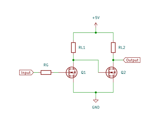
    The code can be configured to invert the output, or you could add an additional MOSFET to invert it a second time. A two-stage, non-inverting buffer is shown in Figure 4.

    Figure 4: A second MOSFET can be used to create a non-inverting buffer

    05. Bidirectional level shifter

    The LCD is controlled from your Pico, so you may expect the signal would only need to go in one direction. However, due to the use of I2C protocol, signals need to pass in both directions. We need a bidirectional level shifter. These can be made using individual MOSFETS, but using a premade level shifter from Adafruit or SparkFun is more convenient. An example is the Adafruit bidirectional level shifter, which has four level shifters on a convenient PCB. This is shown in Figure 5.

    Figure 5: A bidirectional level shifter is available on small PCBs. These can have headers fitted to be used on a breadboard

    The level shifter has just one MOSFET for each channel. This is in an unusual configuration. The circuit can be thought of as two sides, with the left side being for the low voltage and the right for the higher voltage. The MOSFET joins the two together. The schematic diagram is shown in Figure 6.

    Figure 6: The bidirectional level shifter uses two MOSFETs. This works well for signals with pull-up resistors like I2C

    06. How the level shifter works

    If both the low-voltage and high-voltage signals are high, then the MOSFET is off and the signal is high at both sides. If the low-voltage signal (left) drops low, then the MOSFET is in the forward direction and the voltage at the gate will turn the MOSFET on. This will provide a path to ground and so the high-voltage signal (right) will be pulled low. If the high-voltage signal (right) goes low, due to an internal characteristic of the MOSFET a small current is able to flow in the reverse direction. As this happens, the voltage of the source pin dips, causing the MOSFET to turn on. This pulls the voltage down on the low-voltage signal as well.
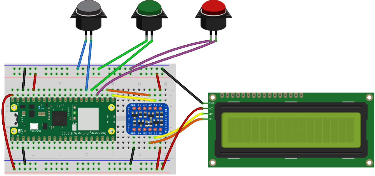
    07. LCD circuit

    The level shifter can be inserted onto the breadboard and connected between your Pico and LCD display. Then it’s just a case of adding three buttons for Start, True, and False. These are shown in Figure 1.

    The top power rail is used for 3.3 V taken from your Pico’s 3.3 V output, and the bottom power rail is 5 V taken from the VBUS supply from the USB port.

    The buttons used are 16 mm push-to-make switches, similar to arcade buttons, but smaller. You can use other push-to-make switches if you prefer.

    08. Download the LCD library

    The libraries that support the LCD display with backpack are available from GitHub. Upload the files lcd_api.py and pico_i2c_lcd.py to your Pico. You can see a demo using pico_i2c_lcd_test.py. This can be useful for checking your wiring is correct, but you will need to change the pins used for SDA (GPIO 16) and SCL (GPIO 17).

    09. Coding the game

    The game code (quizgame.py). starts by setting up the three

    button

    objects, along with

    i2c

    and

    lcd

    . It then reads the file quizfile.txt, which contains the questions.

    Then it enters a loop which ensures that the game can be played over again.

    Within the first few lines of the loop, you can see that it first clears the display, puts a string which starts on the top line, moves to the start of the second line, and then puts another string to that line.

    10. Handling button presses

    The button presses are handled by having a

    while

    loop which runs until an appropriate button is pressed. In the case of the Start button, it just looks for that one button, but when waiting for a true and false, it needs to check both the

    true_button

    and

    false_button

    to see if either is pressed. It keeps track of the score and then displays the score at the end, pausing for five seconds before restarting the game.

    11. The quiz file

    The questions are stored in the file quizfile.txt. This has one line per question. Each line should have three entries separated by a semicolon. The first entry is the top line to display, the second is the second line, and the final entry is a letter T or F to indicate whether the correct answer is

    True

    or

    False

    .

    The file is opened using the

    with

    statement. Using with means that the file will be automatically closed after the program has finished reading in the entries. The

    readlines

    method is used to read all the entries into a list.

    To separate the text to display from the answers, the

    split

    method is used. You may notice that it also uses the

    strip

    method to ignore any whitespaces, such as spaces before the newline character.

    The quiz file is created separately and must be uploaded to Pico.

    Figure 7: The game can be placed inside an enclosure. If you don’t have a 3D printer, you can use a generic case and cut appropriate holes

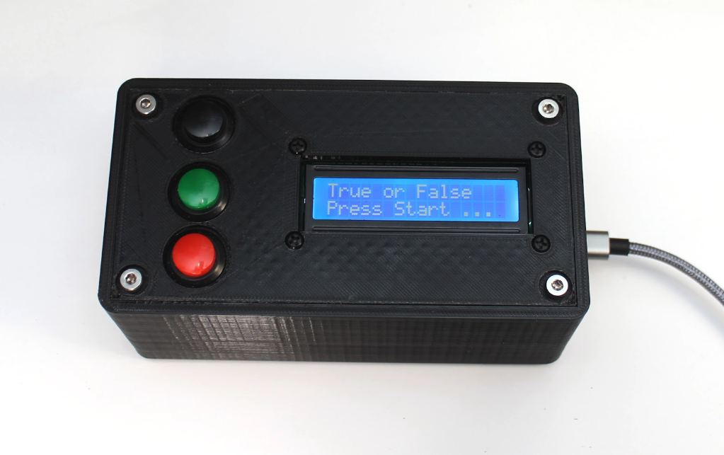
    12. Improving the game

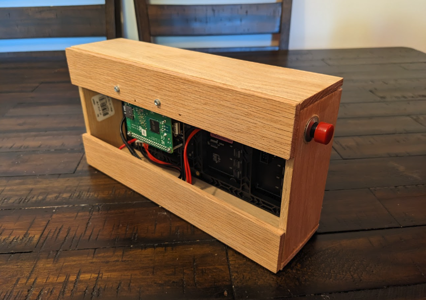
    The game can be placed in an enclosure to make a complete game. You could start with a standard enclosure and cut holes for the display and buttons, or if you have a 3D printer you can download an example from the Penguin Tutor website. One improvement would be to add some error checking. Without error checking, if there is an invalid entry in the quiz file, the program may crash.

    Another possible improvement would be to provide a way to add multiple quizzes rather than just limiting them to a single quiz.

    Download the full code.

  • James Bruton builds a real Zelda Stabilizer Zonai Device

    James Bruton builds a real Zelda Stabilizer Zonai Device

    Reading Time: 2 minutes

    The central gimmick of the new Legend of Zelda: Tears of the Kingdom game is the construction system, which is a lot of fun. You can fuse simple objects to build structures, but you can also add Zonai Devices to increase their functionality. One of those devices is the Stabilizer, which forces any attached vehicle or structure to stand upright. It seems like magic, but James Bruton set out to create a Stabilizer in real life.

    There are many robots and vehicles available today that are capable of balancing themselves, with the Segway being the most famous example. These all rely on mass and inertia to stay upright, but most do that through either moving the base (like a Segway) or with a reaction wheel. Bruton went a slightly different direction for this project and chose to use gyros. When spinning, a gyro resists any motion that pushes it off its axis. By using two gyros, Bruton figured that he could keep the stabilizer upright.

    Bruton built those gyros with automotive disc brakes for the mass wheels. Those rotate in frames constructed using aluminum extrusion and 3D-printed parts. An Arduino Mega 2560 controls the motors, including the brushless DC motors that spin the gyros and the geared DC motors that rotate the gyros to counteract tipping.

    [youtube https://www.youtube.com/watch?v=xMxkgs487QM?feature=oembed&w=500&h=281]

    This doesn’t work quite as well as it does in the game — there are limits to what anyone can achieve with physics. But it is still cool to see in action!

    The post James Bruton builds a real Zelda Stabilizer Zonai Device appeared first on Arduino Blog.

    Website: LINK

  • Arduino Nano ESP32 becomes an ultra-low-powered, pocket-sized Linux PC

    Arduino Nano ESP32 becomes an ultra-low-powered, pocket-sized Linux PC

    Reading Time: 2 minutes

    While many users get them confused, microcontroller development boards and single-board computers are very different things. Single-board computers can run full operating systems, like your desktop PC or laptop does. Microcontroller development boards, like those from Arduino, are usually limited to simpler firmware. But as microcontrollers become more powerful, the line gets blurrier. To prove that, Naveen Kumar built an ultra-low-powered portable Linux computer based on the new Arduino Nano ESP32 development board.

    By modern PC standards, the ESP32-S3 microcontroller in the Nano ESP32 board lacks both processing power and memory. But just a couple of decades ago, the 240MHz clock speed and 512kB of SRAM would have been considered respectable for a lightweight operating system. Clearly, that is still enough to run an operating system today. But there are other challenges that Kumar had to overcome to make that work.

    On the hardware side, Kumar used a Nano ESP32 along with an Arduino UNO R4 WiFi, a CardKB mini keyboard, and a 2.8″ Adafruit TFT touchscreen. The Nano ESP32 acts as a headless computer, while the UNO R4 WiFi, keyboard, and touchscreen act as a terminal to access that computer’s command line. Most Linux distros wouldn’t run on an ESP32 microcontroller, because they expect a different architecture and instruction set. But Max Filippov already ported Linux to work with the Xtensa instruction set used by the ESP32.

    Kumar explains how to compile the kernel for that port and flash it to the Nano ESP32, as well as the UNO R4 WiFi sketch. Hardware setup is quick and easy. You won’t be able to use this to run the latest triple-A games, but you will be able to work with a real Linux OS through the terminal.

    [youtube https://www.youtube.com/watch?v=MpjRqMPWrAg?feature=oembed&w=500&h=281]

    The post Arduino Nano ESP32 becomes an ultra-low-powered, pocket-sized Linux PC appeared first on Arduino Blog.

    Website: LINK

  • DIY EMF detector scans for ghosts and appliances

    DIY EMF detector scans for ghosts and appliances

    Reading Time: 2 minutes

    Electromagnetic Field (EMF) detectors are popular pieces of ghost hunting equipment. The idea is that paranormal apparitions emit a noticeable EMF that proves their existence. But in reality, those EMFs come from electric and electronic devices. And an EMF from you microwave may, for example, interfere with your Wi-Fi network and cause performance problems. So you may want an EMF detector to diagnose such issues and Mirko Pavleski designed a DIY unit you can build.

    This DIY EMF detector is sensitive to electromagnetic radiation and will indicate the strength of any detected fields. A display shows the relative strength of the detected radiation and a buzzer sounds at different frequencies that correspond to the strength, kind of like a Geiger counter. There is almost always some ambient EM radiation around us at all times, so this device adjusts itself at startup to set that as the baseline. Only EM radiation stronger than that baseline will trigger the device.

    To keep the build as simple as possible, Pavleski chose an Arduino Nano board. The antenna, which is just a small piece of copper pipe, connects directly to an analog input pin. Other than that, the only components are a buzzer, an OLED screen, and a 9V battery wired through a power switch. Any EM radiation will induce a tiny current in the antenna, which the Arduino’s analog pin can detect. The stronger the EMF, the greater the voltage on that pin.

    Most EM radiation is very weak and this isn’t the most sensitive device, but it should still be enough to, for instance, detect a live wire in a wall.

    [youtube https://www.youtube.com/watch?v=7KH14ZHu-Nk?feature=oembed&w=500&h=281]

    The post DIY EMF detector scans for ghosts and appliances appeared first on Arduino Blog.

    Website: LINK

  • Raspberry Pi Pico Advanced Kit review

    Raspberry Pi Pico Advanced Kit review

    Reading Time: 2 minutes

    This kit also has 32 guides from Elecrow with things you can make with the components using the more standard MicroPython language on Pico – and credit to the team, there’s not a huge amount of overlap with the types of projects as well.

    Advanced learning

    Despite being called an Advanced Kit, it does let you start from the very basics – getting your Pico to blink its own LED. Then other LEDs. Then switches. Before you know it, you’re measuring distances with ultrasonic sensors, creating Catherine Zeta Jones-style laser traps, and even building a robot arm. The difficulty curve for the projects is fairly good, and tutorials will concisely explain how different components work to better your understanding.

    At the end of the book you’ll build a robot and program it, but it really doesn’t stop there. With all the different things you’ve made, it’s very easy to get ideas to create new projects or combine other ones to extend their functionality.

    Much like this magazine, the guides list the code example and allow you to download it separately in case you need to check it (or just don’t feel like typing it up from scratch).

    With the price and number of components, this really is one of the best ways to help a curious maker learn a ton about electronics, Pico, and coding. You could even upgrade a lot of the projects with a full Raspberry Pi. It’s something we’re definitely keeping close to us for future projects, although we may need to make a Toby Sensor using parts from the box to keep it safe.

    Verdict

    10/10

    Packed full of projects at a very reasonable price, this starter kit will follow even an experienced maker around.

    Specs

    Microcontroller: Raspberry Pi Pico or Pico W

    Components: Sensors, jumper cables, robot kit, breadboards, LEDs, inputs, hand tools

    Language: MicroPython

  • This smart diaper knows when it is ready to be changed

    This smart diaper knows when it is ready to be changed

    Reading Time: 2 minutes

    The traditional method for changing a diaper starts when someone smells or feels the that the diaper has been soiled, and while it isn’t the greatest process, removing the soiled diaper as soon as possible is important for avoiding rashes and infections. Justin Lutz has created an intelligent solution to this situation by designing a small device that alerts people over Bluetooth® when the diaper is ready to be changed.

    Because a dirty diaper gives off volatile organic compounds (VOCs) and small particulates, Lutz realized he could use the Arduino Nicla Sense ME’s built-in BME688 sensor which can measure VOCs, temperature/humidity, and air quality. After gathering 29 minutes of gas and air quality measurements in the Edge impulse Studio for both clean and soiled diapers, he trained a classification model for 300 epochs, resulting in a model with 95% accuracy.

    Based on his prior experience with the Nicla Sense ME’s BLE capabilities and MIT App Inventor, Lutz used the two to devise a small gadget that wirelessly connects to a phone app so it can send notifications when it’s time for a new diaper.

    [youtube https://www.youtube.com/watch?v=Q1BknhEv9cQ?feature=oembed&w=500&h=281]

    To read more about this project, you can check out Lutz’s write-up here on the Edge Impulse docs page.

    The post This smart diaper knows when it is ready to be changed appeared first on Arduino Blog.

    Website: LINK

  • Digital making with Raspberry Pis in primary schools in Sarawak, Malaysia

    Digital making with Raspberry Pis in primary schools in Sarawak, Malaysia

    Reading Time: 6 minutes

    Dr Sue Sentance, Director of our Raspberry Pi Computing Education Research Centre at the University of Cambridge, shares what she learned on a recent visit in Malaysia to understand more about the approach taken to computing education in the state of Sarawak.

    Dr Sue Sentance

    Computing education is a challenge around the world, and it is fascinating to see how different countries and education systems approach it. I recently had the opportunity to attend an event organised by the government of Sarawak, Malaysia, to see first-hand what learners and teachers are achieving thanks to the state’s recent policies.

    Raspberry Pis and training for Sarawak’s primary schools

    In Sarawak, the largest state of Malaysia, the local Ministry of Education, Innovation and Talent Development is funding an ambitious project through which all of Sarawak’s primary schools are receiving sets of Raspberry Pis. Learners use these as desktop computers and to develop computer science skills and knowledge, including the skills to create digital making projects.

    The state of Sarawak, Malaysia circled on a map.
    Sarawak is the largest state of Malaysia, situated on the island of Borneo

    Crucially, the ministry is combining this hardware distribution initiative with a three-year programme of professional development for primary school teachers. They receive training known as the Raspberry Pi Training Programme, which starts with Scratch programming and incorporates elements of physical computing with the Raspberry Pis and sensors.

    To date the project has provided 9436 kits (including Raspberry Pi computer, case, monitor, mouse, and keyboard) to schools, and training for over 1200 teachers.

    The STEM Trailblazers event

    In order to showcase what has been achieved through the project so far, students and teachers were invited to use their schools’ Raspberry Pis to create projects to prototype solutions to real problems faced by their communities, and to showcase these projects at a special STEM Trailblazers event.

    Geographically, Sarawak is Malaysia’s largest state, but it has a much smaller population than the west of the country. This means that towns and villages are very spread out and teachers and students had large distances to travel to attend the STEM Trailblazers event. To partially address this, the event was held in two locations simultaneously, Kuching and Miri, and talks were live-streamed between both venues.

    STEM Trailblazers featured a host of talks from people involved in the initiative. I was very honoured to be invited as a guest speaker, representing both the University of Cambridge and the Raspberry Pi Foundation as the Director of the Raspberry Pi Computing Education Research Centre.

    Solving real-world problems

    The Raspberry Pi projects at STEM Trailblazers were entered into a competition, with prizes for students and teachers. Most projects had been created using Scratch to control the Raspberry Pi as well as a range of sensors.

    The children and teachers who participated came from both rural and urban areas, and it was clear that the issues they had chosen to address were genuine problems in their communities.

    Many of the projects I saw related to issues that schools faced around heat and hydration: a Smart Bottle project reminded children to drink regularly, a shade creator project created shade when the temperature got too high, a teachers’ project told students that they could no longer play outside when the temperature exceeded 35 degrees, and a water cooling system project set off sprinklers when the temperature rose. Other themes of the projects were keeping toilets clean, reminding children to eat healthily, and helping children to learn the alphabet. One project that especially intrigued me was an alert system for large and troublesome birds that were a problem for rural schools.

    Participants showcasing their project at the STEM Trailblazers event.

    The creativity and quality of the projects on show was impressive given that all the students (and many of their teachers) had learned to program very recently, and also had to be quite innovative where they hadn’t been able to access all the hardware they needed to build their creations.

    What we can learn from this initiative

    Everyone involved in this project in Sarawak — including teachers, government representatives, university academics, and industry partners — is really committed to giving children the best opportunities to grow up with an understanding of digital technology. They know this is essential for their professional futures, and also fosters their creativity, independence, and problem-solving skills.

    Young people showcasing their project at the STEM Trailblazers event.

    Over the last ten years, I’ve been fortunate enough to travel widely in my capacity as a computing education researcher, and I’ve seen first-hand a number of the approaches countries are taking to help their young people gain the skills and understanding of computing technologies that they need for their futures.

    It’s good for us to look beyond our own context to understand how countries across the world are preparing their young people to engage with digital technology. No matter how many similarities there are between two places, we can all learn from each other’s initiatives and ideas. In 2021 the Brookings Institution published a global review of how countries are progressing with this endeavour. Organisations such as UNESCO and WEF regularly publish reports that emphasise the importance for countries to develop their citizens’ digital skills, and also advanced technological skills. 

    Young people showcasing their project at the STEM Trailblazers event.

    The Sarawak government’s initiative is grounded in the use of Raspberry Pis as desktop computers for schools, which run offline where schools have no access to the internet. That teachers are also trained to use the Raspberry Pis to support learners to develop hands-on digital making skills is a really important aspect of the project.

    Our commercial subsidiary Raspberry Pi Limited works with a company network of Approved Resellers around the globe; in this case the Malaysian reseller Cytron has been an enormous support in supplying Sarawak’s primary schools with Raspberry Pis and other hardware.

    Schools anywhere in the world can also access the Raspberry Pi Foundation’s free learning and teaching resources, such as curriculum materials, online training courses for teachers, and our magazine for educators, Hello World. We are very proud to support the work being done in Sarawak.

    As for what the future holds for Sarawak’s computing education, at the opening ceremony of the STEM Trailblazers event, the Deputy Minister announced that the event will be an annual occasion. That means every year more students and teachers will be able to come together, share their learning, and get excited about using digital making to solve the problems that matter to them.

    Website: LINK

  • A DIY tube furnace for creating ICs

    A DIY tube furnace for creating ICs

    Reading Time: 2 minutes

    Modern integrated circuit (IC) chips can have transistors as small as two nanometers, which is only about 10 silicon atoms laid end-to-end. At that scale, fabrication looks more like chemistry than any kind of physical manipulation — a machinist isn’t carving tiny transistors into silicon wafers. For many types semiconductors, the fabrication process requires a very powerful furnace. If you’re interested in creating your own ICs, then YouTuber ProjectsInFlight has a video explaining how to build your own furnace.

    This is a design for a tube furnace that can reach 1200°C, similar to the kind that labs buy for many thousands of dollars. Producing that much heat in a controllable manner is not a trivial task and this is much more complicated than constructing a furnace for something like aluminum casting. The heating element is a coil of nichrome wire, which wraps around a quartz glass tube that can withstand the heat. A ridiculous amount of insulation surrounds the tube and wire to contain the heat.

    Nichrome wire heats up through resistance when a current passes through, so you could just connect it to a power source. But that wouldn’t be controllable, so ProjectsInFlight created a control board based on an Arduino UNO Rev3 board. Like a 3D printer controller handling hot end temperature through proportional–integral–derivative (PID), this uses a closed-feedback PID loop to modulate power to the nichrome wire in response to readings from a thermocouple. The control interface has a dial for setting the target temperature and a 16×2 character LCD to show the current temperature detected by the thermocouple. The Arduino uses a solid-state relay (SSR) to modulate the power going through the nichrome wire.

    [youtube https://www.youtube.com/watch?v=oqOlrGPgng8?feature=oembed&w=500&h=281]

    A simple sheet metal enclosure houses the tube and, in a separate area, the control electronics. The furnace seems to be capable of safely reaching the desired temperature, so ProjectsInFlight can now use it for semiconductor experiments.

    The post A DIY tube furnace for creating ICs appeared first on Arduino Blog.

    Website: LINK

  • Pipistrelle Bat Detector

    Pipistrelle Bat Detector

    Reading Time: 3 minutes

    Phil set about designing a method of detecting bats that did not fall foul of frequency issues. His several decades of coding experience and, in particular, his expertise in music synthesis, proved ideal when it came to designing a low-cost device based around Raspberry Pi Pico.

    The Bat Conservation Trust helps you identify bat species. This beauty is a Lesser Horseshoe

    Tuning in

    The first challenge was working out whether there were any bats around. Bats echolocate using ultrasonic frequencies, well beyond human range, but they can’t be heard and are hard to see: “uniquely for mammals, you need technology to detect and study bats,” says Phil. His approach was to have Pico’s sensors scan all the frequencies and seek out the strongest ultrasonic signal. It took him just three weeks to design a Pico-based bat detector that included an operational amp (one which amplifies weak signals), an ultrasonic microphone, a button, and enough software to detect bats and perform speech synthesis.

    Churchyards are great for finding bats

    However, the working prototype board was “an ugly mess and too fragile to take out on surveys,” says Phil, who then turned it into both a printed circuit board and an ultrasonic recorder, adding the ability to record 384kHz/16-bit WAV files to an SD card. This extended the project’s usefulness and meant he could move on to perfecting the surprisingly challenging ultrasonic recording features. Not one to shy away from a technical challenge, Phil chose 128-bit FFTs (fast Fourier transforms) to ensure even the highest frequency bats could be detected. Pico offers exceptional functionality for its size. “Its rich feature set and programmable GPIOs meant that I needed to add the bare minimum of hardware to the design beyond the Pico,” Phil comments “while offering a combination of low cost, low power consumption and the ability to handle 100% duty cycles when processing 128bit FFTs.” This efficiency means Pipistrelle can be used as a passive recorder for four or five nights, “sleeping during the day, listening during the dark, and triggering recordings whenever bat candidate sounds are heard.” These, he likens to music.

    A soprano pipistrelle bat captured in sonogram form by Pipistrelle Bat Detector

    “To hear the bats’ true calls – the bird-like whistles, the peeps, chirps, and high-pitched screams of the Horseshoes – is remarkable.”

    Double duty

    Two years on from his original prototype, there are now three models: BatWalk, a detector to take on bat walks; PippyG ultrasonic recorder; and Pipistrelle itself, which offers both functions. The recorder can either be used manually for on-demand recording, or set to record overnight whenever a bat call is heard. “Overnight recording lets me shut down more of the Pico to get cleaner recordings,” says Phil, an audio purist keen to banish even the slightest operational sounds of the electronics caused by the need to write to the SD card. Each of these can be bought via his Omenie website, and integrated into your bat detection project. A full bill of materials and instructions are provided.

    Phil’s previous project used a Pico to recreate the Doctor Who theme tune

    Though he continues to tinker with the audio, Phil finally feels the project is mature enough for someone to potentially create an Android version of it (since the software is open-source) and sees its further potential for studying other ultrasonic creatures, listing cetacean research, since dolphins use ultrasound, along with small mammals and insects.

  • Mysoltrk is a low-cost solar panel tracking system

    Mysoltrk is a low-cost solar panel tracking system

    Reading Time: 2 minutes

    While a solar panel installed on the top of a roof, lamp post, or the side of a building will produce power, it is nowhere near optimal for achieving the maximum efficiency possible. To get better results, panels are often mounted to pivots and linear actuators/servo motors that continually move to always face the sun. But as Fulvio points out, these motors can be heavy and require extra batteries to function, which is what inspired him to create the mysoltrk to address this shortcoming. Fulvio built his “reinvented” tracker to be small, solid, and sturdy enough to survive outdoors on a balcony or any other space-constrained area like a garden.

    Mysoltrk relies on a pair of very simple yet robust actuators that are each based around a 6V 30RPM geared DC motor, which spins a threaded rod to move an M3 nut closer or further away. When placed in the same plane and connected via a ball joint at the top, this triangle of is able to maneuver the panel in three axes.

    Both motors were then wired to an L298N motor driver which is controlled by an Arduino Nano. Having to incorporate Wi-Fi or a GPS receiver would have introduced far too much complexity, so these components were replaced by a matrix of four photoresistors and a tracking algorithm that, in essence, attempts to balance the readings across all of them in order to point directly at the sun. Perhaps the most incredible part of this project is how no batteries are required thanks to the low-power motors.

    [youtube https://www.youtube.com/watch?v=EcEDuvvm-Bo?feature=oembed&w=500&h=281]

    For more information about mysoltrk, which was recently selected as a finalist in the 2023 Hackaday Prize Green Hacks challenge, you can read Fulvio’s write-up here.

    The post Mysoltrk is a low-cost solar panel tracking system appeared first on Arduino Blog.

    Website: LINK

  • UNO R4 Stars: Meet Monica Rikic

    UNO R4 Stars: Meet Monica Rikic

    Reading Time: 3 minutes

    The launch of the Arduino UNO R4 marks a huge leap forward for our community. For us, it’s also the chance to celebrate the people who bring our ecosystem to life with their bright ideas, radiant enthusiasm, and shining insight.

    That is how the UNO R4 Stars blog post series began: to highlight makers who have not only created amazing projects with Arduino, but who are giving back to the community by sharing as they go and helping others make anything they wish.

    We invite you to discover each profile, hoping you might find a North Star to navigate around an expanding galaxy or venture into completely new universes.

    Born and based in Barcelona, Spain, Monica Rikic is an award-winning artist who has chosen coding and creative electronics as her expressive media. Currently a PhD student at Universitat Oberta de Catalunya’s Network and Information Technologies program, she first encountered Arduino at school and quickly realized the platform would open up infinite opportunities for interactive works capable able of perceiving inputs from the physical context and generating different actions in response.

    “Being a maker means not simply consuming technology, but taking on an active role in the dynamic where, every day, we are in contact with devices and applications that have become our gateways to relate to the world around us, to other people, and to ourselves as well,” she says.

    Over the years, her philosophical and artistic approach have translated into projects such as Hipertèlia, of which she has recently set up a 2023 iteration at the Sala Apolo club in Barcelona thanks to a brand new Arduino UNO R4 WiFi: 20 “balloons” with LEDs inside, interacting with visitors thanks to a camera that tracks their position and communicates it to the system via Wi-Fi. The installation will be on-site until early November — if you are in Barcelona, check it out!

    Rikic has also already developed a new project leveraging the UNO R4 Minima variant: “It’s a weird machine that generates infinite classical music, in collaboration with Rodo. Visitors at the Palau de la Musica can modify the output as they get closer to the installation, speak or even sing to it.” 

    What’s next? She is working on Hipèrbole, a new conceptual project for her EMAP European Residency with Hexagram at Concordia University in Montreal, Canada, exploring the intersection between art and AI from an original standpoint — not to test machines’ creative possibilities, but to experiment with the characteristics that artificial cognitive systems must have to be considered sentient organisms. 

    [youtube https://www.youtube.com/watch?v=biUfhRrCY4E?feature=oembed&w=500&h=281]

     We asked Rikic, “What’s your favorite part of UNO R4?”

    • The 24V tolerance: “Being able to connect to a single power source, even when controlling multiple motors, makes my work a lot simpler.”
    • The built-in mechanism that detects and prevents runtime errors: avoiding short circuits that could potentially harm the board and ruin a whole project is great, especially to keep students motivated.
    • The Qwiic I2C connector: because it allows you to connect different sensors and actuators without soldering.
    • The LED matrix: having a form of direct output helps you immediately see what you can create with electronics.

    To find out more about Rikic’s artistic research and keep an eye out for the new installations she is setting up around the world, bookmark her website or follow her on Instagram.

    The post UNO R4 Stars: Meet Monica Rikic appeared first on Arduino Blog.

    Website: LINK

  • Raspberry Pi-Controlled Automatic Phone Ring Killer

    Raspberry Pi-Controlled Automatic Phone Ring Killer

    Reading Time: 2 minutes

    “I had designed a few other projects using Raspberry Pi, so I had extra Raspberry Pi’s laying around,” Barry explains. “[I] decided to put my extra Raspberry Pi 3B+ to good use as the +5 V power source [of the] automatic timer for the phone ring killer circuit.”

    In the lab

    We feel like everyone needs some kind of maker room if they can manage it. Barry though is a professional.

    “I have my own electronics lab in my house,” Barry mentions. “Including lots of spare parts, and very sophisticated test equipment, having worked as an independent consultant engineer for many years. That makes building these tiny projects a breeze for me.”

    Figure 1: The schematic diagram for the Ring Killer gives an idea of how it all works

    The tiny project involves a little more hardware than software, as it is connected directly into the phone. You can follow along to Figure 1 for the explanation by Barry on how it works.

    “The telephone line attaches to the Ring Detector (components C1, D1, D2, D3, R1, and the input to IC1 the optocoupler). Zener diodes D1 and D2, combined with capacitor C1, allow only high-voltage AC signals to reach the input of the optocoupler. Normal voice and dialling tones don’t affect the ring detector at all. The Ring Signal satisfies these high-voltage AC requirements as it is an 80 V RMS (113 V zero to peak) AC signal superimposed on the 47 V DC idle phone line voltage.

    “When the phone rings, the input of the optocoupler gets activated. The output of the optocoupler then turns on driving R2 to nearly 5 V DC into the gate of the MOSFET Q1, which momentarily loads down the telephone line with 680 ohm resistor R3 signalling the phone company to shut off the ring signal. This happens so fast that you don’t even hear the phone ring. This describes the operation of the circuit when it is in the ‘Sleep’ mode.”

    The Raspberry Pi controls switching sleep mode on or off via powering GPIO pins with a Python program that gets the time from NTP (Network Time Protocol). There’s also a manual toggle in case you’re going to bed early.

    Like a baby

    “I get a much better night’s sleep just knowing that I will not have my slumber interrupted by another annoying telemarketing call at six in the morning,” Barry tells us.

    When we asked about the success of the project, Barry seems not to think there’s much mass appeal for a project like this, as everyone just uses ‘do not disturb’ on their smartphones. While perhaps true, we still think there are plenty of folks who would love to have some manual control over their old landline.

  • Turning a Barbie dreamhouse into a screamhouse with the Arduino UNO R4

    Turning a Barbie dreamhouse into a screamhouse with the Arduino UNO R4

    Reading Time: 2 minutes

    With its bright color scheme and generally upbeat tone, the recently released Barbie movie evokes many of the same feelings as the toy brand. In keeping with this idea, Jaimie and Jay of the Wicked Makers YouTube channel decided to take it in the opposite direction by transforming a Barbie dollhouse into a haunted mansion for Halloween — complete with all of the requisite eerie effects and lighting.

    The duo started by disassembling the interior and repainting the structural components, outside walls, and several other movable objects such as the door and various props. Once this had been completed, the next step involved finding LED filament, many small, discrete LEDs, and a miniature fog machine for creating an additional spookiness factor. The individual LEDs were placed into SLA printed skull lighting fixtures, custom-made clay candles, and inside of the previously pink chandelier where they could then be controlled by an Arduino UNO R4 WiFi

    Beyond these effects, a strand of LED filament was laid into the upper floor to produce a glowing ring for summoning spirits. While a pair of iPads and a phone were placed behind acrylic windows on the second floor and on the ceiling in order to play high quality videos of ghosts and a portal opening up above the summoning ring. 

    To see more about how Jaimie and Jay’s Barbie dreamhouse conversion using an UNO R4, watch their video below!

    [youtube https://www.youtube.com/watch?v=7RullE9aL68?feature=oembed&w=500&h=281]

    The post Turning a Barbie dreamhouse into a screamhouse with the Arduino UNO R4 appeared first on Arduino Blog.

    Website: LINK

  • Cosmic Unicorn (Pico W Aboard) review

    Cosmic Unicorn (Pico W Aboard) review

    Reading Time: 2 minutes

    As with the Galactic Unicorn, it comes preloaded with Pimoroni’s own brand of Pico MicroPython firmware and an auto-running demo program that lets you press one of four tactile buttons to choose from four graphical effects: burning flames, eighties supercomputer (random pixels), cycling rainbow, and nostalgia computer prompt.

    Again, the Pico W RP2040’s PIO state machines are used – along with 12 FM6047 constant current LED drivers – to control the 3.5 mm pixels at around 300 fps at 14-bit resolution, so there’s no sign of any flicker.

    It’s powered by a Pico W soldered on the rear, where you’ll also find a speaker, buttons, battery connector, and Qwiic/STEMMA ports

    Sounds good

    At the rear you’ll find a small 1 W audio speaker along with two Qwiic/STEMMA ports (JST-SH) for connecting breakouts such as sensors. There’s also a battery connector (up to 5.5 V). Positioned at the right-hand edge of the front is a phototransistor to detect light levels. Two metal legs are supplied to use as a stand.

    Programming is relatively simple using the PicoGraphics library for shapes, sprites, and a selection of fonts. Check out the full function list in the Cosmic Unicorn MicroPython reference guide. Inspiration can be found in several code examples, including a neat web-server-based paint program for drawing on the display from a computer.

    Verdict

    9/10

    The larger display area opens up more possibilities for projects, such as a weather dashboard, as well as for playing impressive graphical effects and animations.

    Specs

    Display: 32×32 matrix of RGB LEDs (1024 in total)

    Features: Pico W on board, 10 × push-buttons, mono I2S amp and 1W speaker, 2 × Qwiic/STEMMA ports, battery connector, 2 × metal legs

    Dimensions: 204 × 204 mm

  • Flight tracker with weather

    Flight tracker with weather

    Reading Time: 3 minutes

    “I originally saw someone post a flight tracker using an Arduino but it only displayed overhead flights – when there were no planes, it was a blank screen,” Adam explains. “Myniceaccount posted his own project in the comments on Reddit and it included a clock and a flight tracker using Raspberry Pi, so I followed the instructions and built one.

    The components are accessible from the back of the unit and a power button was added later

    “Afterwards, I kept looking at the empty space and thinking it could be utilised so much more, especially since it was already pulling data from a weather website and flight tracking website. With some help with the coding, more functions were slowly added.” The result is a constantly useful device.

    Raspberry Pi in the sky

    Rather than use a screen, the project incorporates a 64×32 RGB matrix panel. “I liked the way it looks,” Adam says. “It’s very low key and old school while being easier to read (I think). If you had a screen, you could add more information, but it would become too cluttered. This one is simple and to the point.”

    An Adafruit Bonnet controls the panel, which is covered with black tinted acrylic and housed within a case. Once the casing was cut and glued together, Adam set up his Raspberry Pi 3A+ computer and began working on the software.

    The device pulls in the current temperature every ten minutes and issues a forecast every hour

    “Originally the display showed the time, date, and current temperature on the main screen and the flight route, call sign, and aircraft on the other,” Adam continues. “I had the idea to add a weather forecast on the main screen and to add the airline logo, distance, and direction on the flight screen. I just needed help from someone who knew Python to put it all together.

    “I found someone, but he didn’t have the setup to test it, so we spent weeks going back and forth – him sending code and me running it, then sending error reports or feedback on what was working and wasn’t working.” After making the time and date smaller, Adam dabbled with a four-day forecast only to realise three-digit temperatures messed up the screen layout. He chopped a day away.

    Is it a bird?

    Flight tracking remains a very important part of the project. Adam is a keen plane spotter and a device to aid his hobby was his primary motivation. To ensure accuracy, flight information is sourced from FlightRadarAPI.

    “When a plane enters a predetermined ‘box’  made from two lat/long points in the config file along with a minimum altitude, it pulls the flight info and lat/long of the plane and compares it to the lat/long of your location,” Adam explains. “As the plane flies through the box, it updates its distance and direction until it’s out of the box, where it switches back to the clock and weather.”

    The device now takes pride of place beneath Adam’s TV, allowing him to quickly view its information. “With this device I can hear a plane outside and I can discover what it is,” Adam says. “This project was also my first involving an actual display and casing so it was definitely a new experience for me.”

  • Paragraphica camerica

    Paragraphica camerica

    Reading Time: 4 minutes

    Subterranean survival

    Now throw into the mix inspiration from a book entitled An Immense World: How Animal Senses Reveal the Hidden Realms Around Us (Ed Yong), and Bjørn’s thinking gets even more fascinating. The book explores how animals perceive the world differently from humans, and a specific story about the star-nosed mole resonated with him. The book describes “an intelligent hunter and explorer that navigates its world not through sight, but through touch. This creature, living in darkness, has developed a unique way of ‘seeing’ its environment using its star-shaped snout.” This story illustrated to Bjørn “how different forms of intelligence perceive the world in ways that are almost unimaginable to us.”

    Challenge your perceptions

    The fallout from all of this was the design and development of Paragraphica, a context-to-image camera that uses data, not light, to create images, and which offers “a different way of seeing the world, one that is based on data and AI interpretation rather than human perception.” Bjørn feels that it’s a tool that falls “somewhere between critical art and consumer product,” allowing users to explore the ‘dreams’ of AI as he sees it, “providing a glimpse into a form of intelligence that is fundamentally different from our own.”

    Perhaps the most striking thing about the camera is the design of the cover on the front, where typically on a camera you’d find a lens, and we have the star-nosed mole to thank for that. Nature plays a key part in a lot of Bjørn’s designs, and this small burrowing mammal’s antenna-like snout was “the perfect inspiration for the camera.” In addition, Bjørn wanted the front of the camera to evoke a “data collector”, such as a radio antenna or satellite dish.

    Bjørn’s camera works by collecting data related to its location using open APIs, including OpenWeatherMap and Mapbox. This data is used to compose a paragraph (hence the name of the camera) that details a representation of the current place and moment, and this description is then used as the AI image prompt.

    “In a way, you can think of this process as filling in the blanks of a template paragraph,” Bjørn suggests. “I then send this paragraph as a prompt for a text-to-image AI model to convert the paragraph into a ‘photo’.” Some of the resulting images have been surprisingly accurate, “but they never look like the real place – it helps to think of the resulting ‘photo’ as a data visualisation.”

    Bjørn wrote the software for the project, which uses a mix of a local Python script to simulate key presses, and a web application running in a browser. The web app was made using the Noodl platform, “and essentially gathers key parameters from the web, like weather, date, street name, time, and nearby places, and recomposes them into a template description.”

    Dial development

    A Raspberry Pi 4 powers the device from within a 3D-printed shell. “Using a [Raspberry] Pi for the project gave me the freedom to prototype fast and explore some ideas for how it would work,” Bjørn explains. “And I also had a Raspberry Pi 4 with a screen already attached to it laying in my workshop, so this felt like a good starting point.”

    As with most projects that we showcase, there were challenges to overcome during development, including 3D-modelling and 3D-printing the unique mole-inspired casing, and setting up the code and API pipeline for Raspberry Pi.

    Bjørn has also been tweaking the dials on the camera, which enable the user to control the data and AI parameters, thus influencing the final ‘photo’. “I have recently updated the two dials to affect the photo styles and years,” he explains. “Changing the year the photo should be taken at is particularly fun, as you get to picture your street in the 1960s, or 2077 into the future.”

    View-finder

    Bjørn describes the feedback received thus far as “mixed”, with the area of AI igniting a range of reactions and opinions. Some people saw it as a product, but “struggled to connect it to a problem that needed to be solved.” Others have understood the concept and absolutely loved it.

    However, Bjørn feels that it “defiantly shows that the concept and manifestation hit a sensitive point.” He’s clear that his creation was intended to highlight and encourage discussion around AI perception, along with “the increasing use of AI in creative domains and technologies we use daily to capture reality. I think it did the job perfectly.

  • Jumperless breadboard makes prototyping a breeze

    Jumperless breadboard makes prototyping a breeze

    Reading Time: 2 minutes

    Most makers start their initial electronics prototypes on a breadboard, which is great for quickly setting up temporary circuits. But forming the connections requires jumper wires and even a basic project quickly becomes a rats’ nest of wiring that is difficult to manage. Tracking down issues within that tangle of wires is a massive headache, which is why Architeuthis Flux designed this jumperless breadboard to make prototyping a breeze.

    In some ways, the aptly named Jumperless is similar to an FPGA. That’s because it allows for real hardware connections that the user can reconfigure with the push of a button. But Jumperless trades the power and flexibility of an FPGA for ease of use. Instead of the thousands of logic blocks you get in an FPGA, Jumperless gives you just enough to mimic a traditional breadboard. The benefit is in the user-friendly setup. Using a simple netlist file, users can specify which rows on the breadboard should connect to each other and which should connect to the pins of an Arduino Nano board.

    This works using a whole bunch of analog crosspoint switches set by an RP2040 microcontroller based on the netlist file. The PCB contains a plethora of RGB LEDs to indicate which connections are active, as well as information about those connections. To use Jumperless, you simply plug in your components and then enter the connecting rows or Arduino pins via a Wokwi CLI (Command Line Interface) that creates the netlist file for you.

    [youtube https://www.youtube.com/watch?v=0Ia0PMnmLFI?feature=oembed&w=500&h=375]

    If you want Jumperless, it is available on Tindie for $299. Or, because this is an open source project, you can build one yourself using the files on GitHub.

    The post Jumperless breadboard makes prototyping a breeze appeared first on Arduino Blog.

    Website: LINK