Kategorie: Linux

  • Beowulf Clusters, node visualisation and more with Pi VizuWall

    Beowulf Clusters, node visualisation and more with Pi VizuWall

    Reading Time: 6 minutes

    Pi VizuWall is a multi-Raspberry Pi MPI computing system with a difference. And the difference is servo motors!

    Pi VizWall at Maker Faire Miami

    We can thank Estefannie for this gem. While attending Maker Faire Miami earlier this month, she shared a video of Pi VizWall on her Instagram Stories. And it didn’t take long for me to ask for an introduction to the project’s owner, Matt Trask.

    I sent Matt a series of questions in relation to the project so I could write a blog post, but Matt’s replies were so wonderfully detailed that it seems foolish to try and reword them.

    So here are the contents of Matt’s email replies, in their entirety, for you all to enjoy.

    Parallel computing system

    The project is a parallel computing system built according to the Beowulf cluster architecture, the same as most of the world’s largest and fastest supercomputers. It runs a system called MPI (Message Passing Interface) that breaks a program up into smaller pieces that can be sent over the network to other nodes for execution.

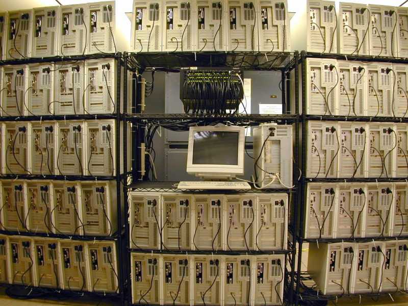
    A Beowulf cluster at Michigan Tech

    Beowulf clusters and MPI were invented in 1994 by a pair of NASA contractors, and they totally disrupted the high-performance computer industry by driving the cost of parallel computing way down. By now, twenty-five years later, the Beowulf cluster architecture is found in approximately 88% of the world’s largest parallel computing systems.

    Going back to university

    I’m currently an undergraduate student at Florida Atlantic University, completing a neglected Bachelor’s Degree from 1983. In the interim, I have had a wonderful career as a Computer Engineer, working with every generation of Personal Computer technology. My main research that I do at the University is focused on a new architecture for parallel clusters that uses traditional Beowulf hardware (enterprise-class servers with InfiniBand as the interconnect fabric) but modifies the Linux operating system in order to combine the resources (RAM, processor cores) from all the nodes in the cluster and make them appear as a single system that is the sum of all the resources. This is also known as a ‘virtual mainframe’.

    The Ninja Gap

    In the world of parallel supercomputers (branded ‘high-performance computing, or HPC), system manufacturers are motivated to sell their HPC products to industry, but industry has pushed back due to what they call the “Ninja Gap”. MPI programming is hard. It is usually not learned until the programmer is in grad school at the earliest, and given that it takes a couple of years to achieve mastery of any particular discipline, most of the proficient MPI programmers are PhDs. And this, is the Ninja Gap — industry understands that the academic system cannot and will not be able to generate enough ‘ninjas’ to meet the needs of industry if industry were to adopt HPC technology.

    Studying Message Passing Interface

    As part of my research into parallel computing systems, I have studied the process of learning to program with MPI and have found that almost all current practitioners are self-taught, coming from disciplines other than computer science. Actual undergraduate CS programs rarely offer MPI programming. Thus my motivation for building a low-cost cluster system with Raspberry Pis, in order to drive down the entry-level costs.

    This parallel computing system, with a cost of under $1000, could be deployed at any college or community college rather than just at elite research institutions, as is done [for parallel computing systems] today.

    Moving parts

    The system is entirely open source, using only standard Raspberry Pi 3B+ boards and Raspbian Linux. The version of MPI that is used is called MPICH, another open-source technology that is readily available.

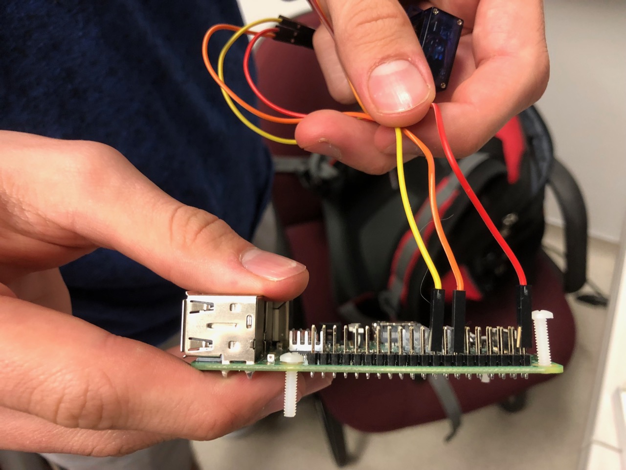
    Perhaps one of the more interesting features of the cluster is that each of the Pi boards is mounted on a clear acrylic plate that is attached to a hinging mechanism. Each node is capable of moving through about 90 degrees under software control because a small electric servo motor is embedded in the hinging mechanism. The acrylic parts are laser-cut, and the hinge parts have been 3D printed for this prototype.

    Raspbian Linux, like every other Linux version, contains information about CPU utilization as part of the kernel’s internal data. This performance data is available through the /proc filesystem at runtime, allowing a relatively simple program to maintain percent-busy averages over time. This data is used to position the node via its servo, with a fully idle node laying down against the backboard and a full busy node rotating up to ninety degrees.

    Visualizing node activity

    The purpose of this motion-related activity is to permit the user to visualize the operation of the cluster while executing a parallel program, showing the level of activity at each node via proportional motion. Thus the name Pi VizuWall.

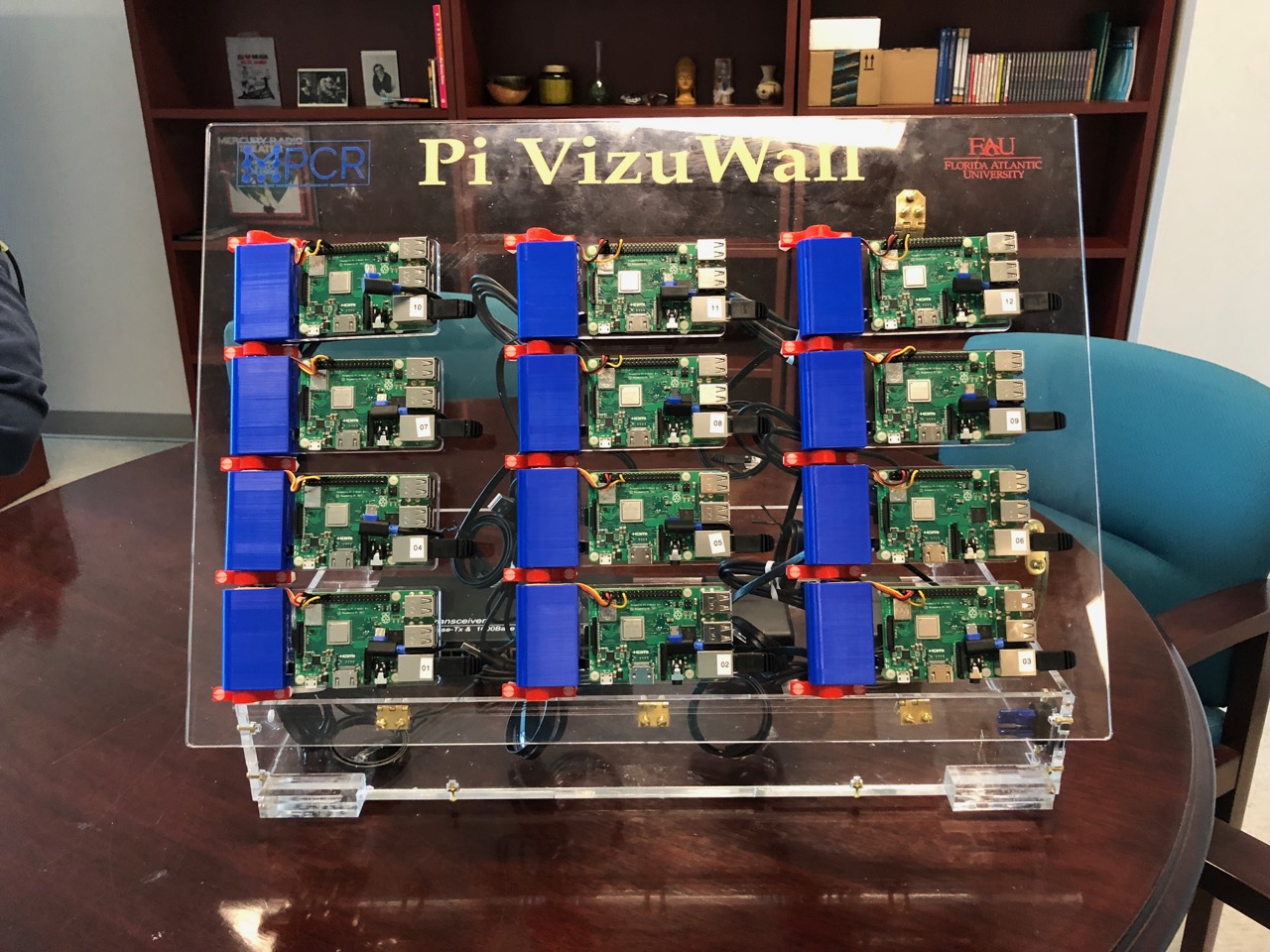
    Other than the twelve Pi 3s, I used 12 Tower Pro micro servos (SG90 Digital) and assorted laser-cut acrylic and 3D-printed parts (AI and STL files available on request), as well as a 14-port Ethernet switch for interconnects and two 12A 6-port USB power supplies along with Ethernet cable and USB cables for power.

    The future of Pi VizuWall

    The original plan for this project was to make a 4ft × 8ft cluster with 300 Raspberry Pis wired as a Beowulf cluster running MPICH. When I proposed this project to my Lab Directors at the university, they balked at the estimated cost of $20–25K and suggested a scaled-down prototype first. We have learned a number of lessons while building this prototype that should serve us well when we move on to building the bigger one. The first lesson is to use CNC’d aluminum for the motor housings instead of 3D-printed plastic — we’ve seen some minor distortion of the printed plastic from the heat generated in the servos. But mainly, this will permit us to have finer resolution when creating the splines that engage with the shaft of the servo motor, solving the problem of occasional slippage under load that we have seen with this version.

    The other major challenge was power distribution. We look forward to using the Pi’s PoE capabilities in the next version to simplify power distribution. We also anticipate evaluating whether the Pi’s wireless LAN capability is suitable for carrying the MPI message traffic, given that the wired Ethernet has greater bandwidth. If the wireless bandwidth is sufficient, we will potentially use Pi Zero W computers instead of Pi 3s, doubling the number of nodes we can install on a 4×8’ backboard.

    Website: LINK

  • Watch Game of Thrones with a Raspberry Pi-powered Drogon

    Watch Game of Thrones with a Raspberry Pi-powered Drogon

    Reading Time: 2 minutes

    Channel your inner Targaryen by building this voice-activated, colour-changing, 3D-printed Drogon before watching the next episode of Game of Thrones.

    Winter has come

    This is a spoiler-free zone! I’ve already seen the new episode of season 8, but I won’t ruin anything, I promise.

    Even if you’ve never watched an episode of Game of Thrones (if so, that’s fine, I don’t judge you), you’re probably aware that the final season has started.

    And you might also know that the show has dragons in it — big, hulking, scaley dragons called Rhaegal, Viserion, and Drogon. They look a little something like this:Daenerys-Targaryen-game-of-thrones

    Well, not anymore. They look like this now:

    04_15_GameOfThrones_S07-920x584

    Raspberry Pi voice-responsive dragon!

    The creator of this project goes by the moniker Botmation. To begin with, they 3D printed modified a Drogon model they found on Thingiverse. Then, with Dremel in hand, they modified the print, to replace its eyes with RGB LEDs. Before drawing the LEDs through the hollowed-out body of the model, they soldered them to wires connected to a Raspberry Pi Zero W‘s GPIO pins.

    Located in the tin beneath Drogon, the Pi Zero W is also equipped with a microphone and runs the Python code for the project. And thanks to Google’s Speech to Text API, Drogon’s eyes change colour whenever a GoT character repeats one of two keywords: white turns the eyes blue, while fire turns them red.

    If you’d like more information about building your own interactive Drogon, here’s a handy video. At the end, Botmation asks viewers to help improve their code for a cleaner voice-activation experience.

    3D printed Drogon with LED eyes for Game of Thrones

    Going into the final season of Game of Thrones with your very own 3D printed Drogron dragon! The eyes are made of LEDs that changes between Red and Blue depending on what happens in the show. When you’re watching the show, Drogon will watch the show with you and listen for cues to change the eye color.

    Drogon for the throne!

    I’ve managed to bag two of the three dragons in the Pi Towers Game of Thrones fantasy league, so I reckon my chances of winning are pretty good thanks to all the points I’ll rack up by killing White Walker.

    Wait — does killing a White Walker count as a kill, since they’re already dead?

    Ah, crud.

    Website: LINK

  • Raspberry Pi-controlled brass bell for ultimate the wake-up call

    Raspberry Pi-controlled brass bell for ultimate the wake-up call

    Reading Time: 2 minutes

    Not one for rising with the sun, and getting more and more skilled at throwing their watch across the room to snooze their alarm, Reddit user ravenspired decided to hook up a physical bell to a Raspberry Pi and servo motor to create the ultimate morning wake-up call.

    DIY RASPBERRY PI BELL RINGING ALARM CLOCK!

    This has to be the harshest thing to wake up to EVER!

    Wake up, Boo

    “I have difficulty waking up in the morning” admits ravenspired, who goes by the name Darks Pi on YouTube. “My watch isn’t doing its job.”

    Therefore, ravenspired attached a bell to a servo motor, and the servo motor to a Raspberry Pi. Then they wrote Python code in Raspbian’s free IDE software Thonny that rings the bell when it’s time to get up.

    “A while loop searches for what time it is and checks it against my alarm time. When the alarm is active, it sends commands to the servo to move.”

    Ouch!

    While I’d be concerned about how securely attached the heavy brass bell above my head is, this is still a fun project, and an inventive way to address a common problem.

    And it’s a lot less painful than this…

    The Wake-up Machine TAKE #2

    I built an alarm clock that slapped me in the face with a rubber arm to wake me up.I built an alarm clock that wakes me up in the morning by slapping me in the face with a rubber arm.

    Have you created a completely over-engineered solution for a common problem? Then we want to see it!

    Website: LINK

  • Coding Breakout’s brick-breaking action | Wireframe #11

    Coding Breakout’s brick-breaking action | Wireframe #11

    Reading Time: 3 minutes

    Atari’s Breakout was one of the earliest video game blockbusters. Here’s how to recreate it in Python.

    The original Breakout, designed by Nolan Bushnell and Steve Bristow, and famously built by a young Steve Wozniak.

    Atari Breakout

    The games industry owes a lot to the humble bat and ball. Designed by Allan Alcorn in 1972, Pong was a simplified version of table tennis, where the player moved a bat and scored points by ricocheting a ball past their opponent. About four years later, Atari’s Nolan Bushnell and Steve Bristow figured out a way of making Pong into a single-player game. The result was 1976’s Breakout, which rotated Pong’s action 90 degrees and replaced the second player with a wall of bricks.

    Points were scored by deflecting the ball off the bat and destroying the bricks; as in Pong, the player would lose the game if the ball left the play area. Breakout was a hit for Atari, and remains one of those game ideas that has never quite faded from view; in the 1980s, Taito’s Arkanoid updated the action with collectible power-ups, multiple stages with different layouts of bricks, and enemies that disrupted the trajectory of the player’s ball.

    Breakout had an impact on other genres too: game designer Tomohiro Nishikado came up with the idea for Space Invaders by switching Breakout’s bat with a base that shot bullets, while Breakout’s bricks became aliens that moved and fired back at the player.

    Courtesy of Daniel Pope, here’s a simple Breakout game written in Python. To get it running on your system, you’ll first need to install Pygame Zero. And download the code for Breakout here.

    Bricks and balls in Python

    The code above, written by Daniel Pope, shows you just how easy it is to get a basic version of Breakout up and running in Python, using the Pygame Zero library. Like Atari’s original, this version draws a wall of blocks on the screen, sets a ball bouncing around, and gives the player a paddle, which can be controlled by moving the mouse left and right. The ball physics are simple to grasp too. The ball has a velocity, vel – which is a vector, or a pair of numbers: vx for the x direction and vy for the y direction.

    The program loop checks the position of the ball and whether it’s collided with a brick or the edge of the play area. If the ball hits the left side of the play area, the ball’s x velocity vx is set to positive, thus sending it bouncing to the right. If the ball hits the right side, vx is set to a negative number, so the ball moves left. Likewise, when the ball hits the top or bottom of a brick, we set the sign of the y velocity vy, and so on for the collisions with the bat and the top of the play area and the sides of bricks. Collisions set the sign of vx and vy but never change the magnitude. This is called a perfectly elastic collision.

    To this basic framework, you could add all kinds of additional features: a 2012 talk by developers Martin Jonasson and Petri Purho, which you can watch on YouTube here, shows how the Breakout concept can be given new life with the addition of a few modern design ideas.

    You can read this feature and more besides in Wireframe issue 11, available now in Tesco, WHSmith, and all good independent UK newsagents.

    Or you can buy Wireframe directly from us – worldwide delivery is available. And if you’d like to own a handy digital version of the magazine, you can also download a free PDF.

    Make sure to follow Wireframe on Twitter and Facebook for updates and exclusives, and for subscriptions, visit the Wireframe website to save 49% compared to newsstand pricing!

    Website: LINK

  • One machine that does it all!

    One machine that does it all!

    Reading Time: 2 minutes

    One machine that does it all!

    Arduino TeamApril 10th, 2019

    While having a huge workshop with every tool imaginable is ideal, if you have limited funds and/or space, then Mark Miller’s gantry-style machine could be just the thing you need. 

    In this setup, the workpiece moves via a stepper motor and a rod system on the bottom, while top support rods accommodate interchangeable tooling.

    Tools compatible with the machine (so far) include a 10 watt laser, marker, knife for stencil carving, and a motor/router bit combo for light milling operations. An Arduino is employed for control, while user interface is provided by a series of buttons and a joystick. 

    Miller even wrote custom software to transform CAD files into sketches that can be directly loaded onto the machine.

    The project is still a work in progress, so be sure to follow along in its Hackaday write-up here.

    [youtube https://www.youtube.com/watch?v=kmhAgCZRbOA?feature=oembed&w=500&h=281]

    Website: LINK

  • Bind MIDI inputs to LED lights using a Raspberry Pi

    Bind MIDI inputs to LED lights using a Raspberry Pi

    Reading Time: 2 minutes

    Blinky lights and music created using a Raspberry Pi? Count us in! When Aaron Chambers shared his latest project, Py-Lights, on Reddit, we were quick to ask for more information. And here it is:

    [Seizure Warning] Raspberry Pi MIDI LED demo

    A demo for controlling LEDs on a Raspberry Pi Song: Bassnectar – Chasing Heaven https://github.com/aaron64/py-lights

    Controlling lights with MIDI commands

    Tentatively titled Py-Lights, Aaron’s project allows users to assign light patterns to MIDI actions, creating a rather lovely blinky light display.

    For his example, Aaron connected a MIDI keyboard to a strip of RGB LEDs via a Raspberry Pi that ran his custom Python code.

    Aaron explains on Reddit:

    The program I made lets me bind “actions” (strobe white, flash blue, disable all colors, etc.) to any input and any input type (hold, knob, trigger, etc.). And each action type has a set of parameters that I bind to the input. For example, I have a knob that changes a strobe’s intensity, and another knob that changes its speed.

    The program updates each action, pulls its resulting color, and adds them together, then sends that to the LEDs. I’m using rtmidi for reading the midi device and pigpio for handling the LED output.

    Aaron has updated the Py-Lights GitHub repo for the project to include a handy readme file and a more stable build.

    Website: LINK

  • Vacuum cleaner turned into unique MIDI instrument

    Vacuum cleaner turned into unique MIDI instrument

    Reading Time: 2 minutes

    Vacuum cleaner turned into unique MIDI instrument

    Arduino TeamApril 9th, 2019

    When you see a vacuum cleaner, most people see a useful implement to keep their carpets clean. James Bruton, however, envisioned another use—as a musical instrument. His new project, which made its appearance this year on April Fools’ Day, sucks air through 12 recorders, allowing it to play a full octave and the melody and lead from “Africa” by Toto… or so he’d have you believe!

    In reality, power for his instrument comes from a separate Henry Hoover in another room, blowing air through the normally-suction tube of the broken device on the screen. An Arduino Mega, along with a MIDI shield, enables it to open and close air lines to each of the 12 recorders as needed. 

    Check out how it was made in the first video below and the original fake in the second.

    [youtube https://www.youtube.com/watch?v=SAcYxc1M55s?feature=oembed&w=500&h=281]

    [youtube https://www.youtube.com/watch?v=gOlmo1gX5Wc?feature=oembed&w=500&h=281]

    Website: LINK

  • Go all cyberpunk with this laser-spiked jacket!

    Go all cyberpunk with this laser-spiked jacket!

    Reading Time: 2 minutes

    Go all cyberpunk with this laser-spiked jacket!

    Arduino TeamApril 9th, 2019

    Your leather jacket might look cool, but one thing it’s missing—unless you’re maker “abetusk” or perhaps a Japanese musician—is lasers! 

    After seeing Yoshii Kazuya’s laser-spiked outfit, ‘tusk decided to create an excellent version of the getup by embedding 128 laser diodes embedded in his own jacket. These lasers are powered by an Arduino Nano, along with a pair of I2C PWM output boards, allowing them to be switched in sets of four. 

    The lasers can be controlled either by joystick, via a microphone in order to react to sound, or in a looping ‘twinkle’ pattern. 

    More information on the project is available in this write-up as well as on GitHub, which includes Arduino code and other files needed to build your own.

    After seeing Wei Chieh Shi’s laser jacket design, I wanted to create my own. These instructions show how to modify a jacket to add laser diodes and control them electronically to produce different laser light patterns. The laser diodes give the jacket an appearance of being “spiky”, like having metal spikes but with red laser light. The effect is especially striking in environments with fog or smoke as the laser light path shows a trail from where it originates.

    The concept and execution is relatively simple but care has to be taken to make sure that the electronics, wiring and other aspects of the jacket don’t fail when in use. Much of the subtlety and complexity of the project is providing proper wire routing and making sure that strain relief for the electronics and connections is provided so that it’s resilient under normal wear.

    Assuming the basic parts are available (soldering iron, multimeter, wire strippers, laser cutter, etc.) I would estimate that this project is about $300 in raw materials and about 20 hours worth of labor.

    Depending on the battery used, the jacket can operate for about an hour or two continuously. Spare batteries can be carried around and used to replace the depleted batteries if need be.

    [youtube https://www.youtube.com/watch?v=gdBWdDNlHQY?feature=oembed&w=500&h=281]

    Website: LINK

  • Raspberry Pi underwater camera drone | The MagPi 80

    Raspberry Pi underwater camera drone | The MagPi 80

    Reading Time: 4 minutes

    Never let it be said that some makers won’t jump in at the deep end for their ambitious experiments with the Raspberry Pi. When Ievgenii Tkachenko fancied a challenge, he sought to go where few had gone before by creating an underwater drone, successfully producing a working prototype that he’s now hard at work refining.

    Inspired by watching inventors on the Discovery Channel, Ievgenii has learned much from his endeavour. “For me it was a significant engineering challenge,” he says, and while he has ended up submerging himself within a process of trial-and-error, the results so far have been impressive.

    Pi dive

    The project began with a loose plan in Ievgenii’s head. “I knew what I should have in the project as a minimum: motions, lights, camera, and a gyroscope inside the device and smartphone control outside,” he explains. “Pretty simple, but I didn’t have a clue what equipment I would be able to use for the drone, and I was limited by finances.”

    Bearing that in mind, one of his first moves was to choose a Raspberry Pi 3B, which he says was perfect for controlling the motors, diodes, and gyroscope while sending video streams from a camera and receiving commands from a control device.

    The Raspberry Pi 3 sits in the housing and connects to a LiPo battery that also powers the LEDs and motors

    “I was really surprised that this small board has a fully functional UNIX-based OS and that software like the Node.js server can be easily installed,” he tells us. “It has control input and output pins and there are a lot of libraries. With an Ethernet port and wireless LAN and a camera, it just felt plug-and-play. I couldn’t find a better solution.”

    The LEDs are attached to radiators to prevent overheating, and a pulse driver is used for flashlight control

    Working with a friend, Ievgenii sought to create suitable housing for the components, which included a twin twisted-pair wire suitable for transferring data underwater, an electric motor, an electronic speed control, an LED together with a pulse driver, and a battery. Four motors were attached to the outside of the housing, and efforts were made to ensure it was waterproof. Tests in a bath and out on a lake were conducted.

    Streaming video

    With a WiFi router on the shore connected to the Raspberry Pi via RJ45 connectors and an Ethernet cable, Ievgenii developed an Android application to connect to the Raspberry Pi by address and port (“as an Android developer, I’m used to working with the platform”). This also allowed movement to be controlled via the touchscreen, although he says a gamepad for Android can also be used. When it’s up and running, the Pi streams a video from the camera to the app — “live video streaming is not simple, and I spent a lot of time on the solution” — but the wired connection means the drone can only currently travel as far as the cable length allows.

    The camera was placed in this transparent waterproof case attached to the front of the waterproof housing

    In that sense, it’s not perfect. “It’s also hard to handle the drone, and it needs to be enhanced with an additional controls board and a few more electromotors for smooth movement,” Ievgenii admits. But as well as wanting to base the project on fast and reliable C++ code and make use of a USB 4K camera, he can see the future potential and he feels it will swim rather than sink.

    “Similar drones are used for boat inspections, and they can also be used by rescue squads or for scientific purposes,” he points out. “They can be used to discover a vast marine world without training and risks too. In fact, now that I understand the Raspberry Pi, I know I can create almost anything, from a radio electronic toy car to a smart home.”

    The MagPi magazine

    This article was lovingly borrowed from the latest issue of The MagPi magazine. Pick up your copy of issue 80 from your local stockist, online, or by downloading the free PDF.

    Subscribers to The MagPi also get a rather delightful subscription gift!

    Website: LINK

  • This incredible word clock is controlled by 114 servos

    This incredible word clock is controlled by 114 servos

    Reading Time: 3 minutes

    This incredible word clock is controlled by 114 servos

    Arduino TeamApril 8th, 2019

    Word clocks normally use an array of lights to show the time, and although this project does use lights, how it works is much different than others. 

    LEDs for the device are hidden behind a thin layer of PVC, while 114 tiny SG90 servos move the lights and their 3D-printed frames back and forth. The result is a stunning display where the time is spelled out by the appropriate characters. These progressively come into focus, setting them apart from inactive letters which appear to fade into the background.

    An Arduino Nano drives the assembly, along with an infrared controller setup and an RTC module for accurate timekeeping. A demo can be seen in the first video below, and the very involved build process is highlighted in the second clip. 

    What has 114 LEDs and is always running? As you may know the answer is a word clock. What has 114 LEDs + 114 servos and is always moving? The answer is this servo controlled word clock.

    For this project I teamed up with a friend of mine which turned out to be a must because of the large effort of this build. In addition, my electronic and his mechanical skillset complemented each other quite well. The idea for this adaptation of the popular word clock came to us while we were making a regular one as Christmas gift. There, we noticed that it is also possible to project the letters from the back onto a white sheet of paper. At the time this was only a workaround solution to hide our crappy craftsmanship since we ended up with a lot of bubbles while attaching a vinyl sticker with the letters to the back of a glass plate. We then noticed that one can achieve interesting effects when bending the sheet of paper since the letters change size and become blurred. This made us come up with the idea to make a word clock where the letters are projected from the back onto a screen and can be moved back and forth to change the size of the projected image. At first we were a bit reluctant to build this project because of the costs and effort it takes when you want to move each of the 114 letters individually. So we tossed with the idea to make a version where just every word that is used to display the time can be moved back and forth. However, after seeing that the Epilog contest was coming up on Instructables asking for epic projects, and also after finding relatively cheap servo motors, we decided to go all the way and make a proper version where each letter is individually controlled by a servo

    [youtube https://www.youtube.com/watch?v=ZvBI-v3uBo8?feature=oembed&w=500&h=281]

    [youtube https://www.youtube.com/watch?v=f-2w-D18m9c?feature=oembed&w=500&h=281]

    Website: LINK

  • Hacking an Etch-A-Sketch with a Raspberry Pi and camera: Etch-A-Snap!

    Hacking an Etch-A-Sketch with a Raspberry Pi and camera: Etch-A-Snap!

    Reading Time: 2 minutes

    Kids of the 1980s, rejoice: the age of the digital Etch-A-Sketch is now!

    What is an Etch-A-Sketch

    Introduced in 1960, the Etch-A-Sketch was invented by Frenchman André Cassagnes and manufactured by the Ohio Art Company.

    The back of the Etch-A-Sketch screen is covered in very fine aluminium powder. Turning one of the two directional knobs runs a stylus across the back of the screen, displacing the powder and creating a dark grey line visible in the front side.

    can it run DOOM?

    yes

    The Etch-A-Sketch was my favourite childhood toy. So you can imagine how excited I was to see the Etch-A-Snap project when I logged into Reddit this morning!

    Digital Etch-A-Sketch

    Yesterday, Martin Fitzpatrick shared on Reddit how he designed and built Etch-A-Snap, a Raspberry Pi Zero– and Camera Module–connected Etch-A-Sketch that (slowly) etches photographs using one continuous line.

    Etch-A-Snap is (probably) the world’s first Etch-A-Sketch Camera. Powered by a Raspberry Pi Zero (or Zero W), it snaps photos just like any other camera, but outputs them by drawing to an Pocket Etch-A-Sketch screen. Quite slowly.

    Unless someone can show us another Etch-A-Sketch camera like this, we’re happy to agree that this is a first!

    Raspberry Pi–powered Etch-A-Sketch

    Powered by four AA batteries and three 18650 LiPo cells, Etch-A-Snap houses the $5 Raspberry Pi Zero and two 5V stepper motors within a 3D-printed case mounted on the back of a pocket-sized Etch-A-Sketch.

    Photos taken using the Raspberry Pi Camera Module are converted into 1-bit, 100px × 60px, black-and-white images using Pillow and OpenCV. Next, these smaller images are turned into plotter commands using networkx. Finally, the Raspberry Pi engages the two 5V stepper motors to move the Etch-A-Sketch control knobs, producing a sketch within 15 minutes to an hour, depending on the level of detail in the image.

    Build your own Etch-A-Snap

    On his website, Martin goes into some serious detail about Etch-A-Snap, perfect for anyone interested in building their own, or in figuring out how it all works. You’ll find an overview with videos, along with breakdowns of the build, processing, drawing, and plotter.

    Website: LINK

  • Good luck to OKdo, a brand new global technology company in the microcontroller and IoT space

    Good luck to OKdo, a brand new global technology company in the microcontroller and IoT space

    Reading Time: 2 minutes

    Good luck to OKdo, a brand new global technology company in the microcontroller and IoT space

    Arduino TeamApril 8th, 2019

    OKdo’s focus is to create an ‘outstanding’ experience for all microcontroller and IoT customers, whatever their background, goals and ambitions. Bringing them the latest products, solutions and ideas to inspire and enable them to create technology that makes life better.

    Visit OKdo’s new website to see the Arduino-based inspirational Industrial case study where Fluid Intelligence’s oil performance monitoring service enables  industrial customers in the Logistics, Pulp & Paper, Manufacturing, Chemical and Energy sectors to maximise their operational reliability and reduce the waste generated by up to 50%.

    “We’re excited to be partnering with OKdo. With our roots in open source, Arduino has transformed into a company that serves professional designers by providing complete IoT platforms, as well as continuing to enable students, educators and makers to innovate by making complex technology simple to use. There are a lot of enterprises that need simple and secure technology for adding connectivity to their devices, together, Arduino and OKdo can make that happen,” explained Massimo Banzi, CTO and Co-founder of Arduino.

    “At OKdo we’re excited to work with Arduino to help them meet their objectives and grow their business. We support makers, entrepreneurs, start-ups and global businesses turn their visions into reality. Like Arduino, the philosophy behind OKdo is to put technology in the hands of those who have the biggest potential. Together with Arduino we can work with customers and businesses to help them do something amazing,” commented Richard Curtin, SVP Technology at OKdo.

    To find out more about OKdo, visit their website or follow them on Twitter, YouTube, LinkedIn, Facebook, and Instagram.

    Website: LINK

  • New Wolfram Mathematica free resources for your Raspberry Pi

    New Wolfram Mathematica free resources for your Raspberry Pi

    Reading Time: 3 minutes

    We’ve worked alongside the team at Wolfram Mathematica to create ten new free resources for our projects site, perfect to use at home, or in your classroom, Code Club, or CoderDojo.

    Try out the Wolfram Language today, available as a free download for your Raspberry Pi (download details are below).

    The Wolfram Language

    The Wolfram language is particularly good at retrieving and working with data, like natural language and geographic information, and at producing visual representations with an impressively small amount of code. The language does a lot of the heavy lifting for you and is a great way to let young learners in particular work with data to quickly produce real results.

    If you’d like to learn more about the Wolfram Language on the Raspberry Pi, check out this great blog post written by Lucy, Editor of The MagPi magazine!

    Weather dashboard

    Wolfram Mathematica Raspberry Pi Weather Dashboard

    My favourite of the new projects is the weather dashboard which, in a few quick steps, teaches you to create this shiny-looking widget that takes the user’s location, finds their nearest major city, and gets current weather data for it. I tried this out with my own CoderDojo club and it got a very positive reception, even if Dublin weather usually does report rain!

    Coin and dice

    Wolfram Mathematica Raspberry Pi Coin and Dice

    The coin and dice project shows you how to create a coin toss and dice roller that you can use to move your favourite board game into the digital age. It also introduces you to creating interfaces and controls for your projects, choosing random outcomes, and displaying images with the Wolfram Language.

    Day and night

    In the day and night tracker project, you create a program that gives you a real-time view of where the sun is up right now and lets you check whether it’s day or night time in a particular country. This is not only a pretty cool way to learn about things like time zones, but also shows you how to use geographic data and create an interactive experience in the Wolfram Language.

    Sentimental 8-ball

    Wolfram Mathematica Raspberry Pi 8-ball

    In Sentimental 8-Ball, you create a Magic 8-Ball that picks its answers based on how positive or negative the mood of the user’s question seems. In doing so, you learn to work with lists and use the power of sentiment analysis in the Wolfram Language.

    Face swap

    Wolfram Mathematica Raspberry Pi face swap

    This fun project lets you take a photo of you and your friend and have the Wolfram Language identify and swap your faces! Perfect for updating your profile photo, and also a great way to learn about functions and lists!

    More Wolfram Mathematica projects

    That’s only half of the selection of great new projects we’ve got for you! Go check them out, along with all the other Wolfram Language projects on our projects site.

    Download the Wolfram Language and Mathematica to your Raspberry Pi

    Mathematica and the Wolfram Language are included as part of NOOBS, or you can download them to Raspbian on your Raspberry Pi for free by entering the following commands into a terminal window and pressing Enter after each:

    sudo apt-get update
    sudo apt-get install wolfram-engine

    Website: LINK

  • 135 teams will run their experiments on the ISS for Astro Pi Mission Space Lab 2018-19

    135 teams will run their experiments on the ISS for Astro Pi Mission Space Lab 2018-19

    Reading Time: 4 minutes

    In this year’s round of Astro Pi Mission Space Lab, 135 teams will run their experiments on the ISS!

    CSA Astronaut David Saint-Jacques congratulates all the participants on behalf of ESA and the Raspberry Pi Foundation.

    CSA astronaut David Saint-Jacques aboard the International Space Station – ENGLISH

    CSA astronaut David Saint-Jacques introduces Phase Three of the Raspberry Pi ESA Astro Pi Challenge aboard the International Space Station. Pretty cool, right?

    (Find the French version of the video at the bottom of this blog post.)

    Astro Pi Challenge 2018/2019

    In September of last year, the European Space Agency and Raspberry Pi Foundation launched the European Astro Pi Challenge for 2018/2019.

    It offers students and young people the amazing opportunity to conduct scientific investigations in space, by writing computer programs that run on Raspberry Pi computers aboard the International Space Station.

    The Challenge offers two missions: Mission Zero and Mission Space Lab.

    Astro Pi Mission Space Lab

    Mission Space Lab, our more advanced mission, invited teams of students and young people under 19 years of age to take part in Mission Space Lab by submitting an idea for a scientific experiment to be run on the Astro Pi units.

    Astro PI IR on ISS

    Teams were able to choose between two themes for their experiments: Life in space and Life on Earth. Teams that chose the ‘Life on Earth’ theme were tasked with using the Astro Pi computer Izzy, fitted with a near-infrared camera facing out of an ISS window, to study the Earth. For ‘Life in space’, teams used the Astro Pi computer Ed, which is equipped with a camera for light sensing, and investigate life inside the Columbus module of the ISS.

    There are four phases to Mission Space Lab:

      • Phase 1 – Design (September- October 2018)
        • Come up with an idea for your experiment
      • Phase 2 – Create (November 2018 to March 2019)
        • Code your program and test your experiment on Earth
      • Phase 3 – Deploy (April 2019)
        • Your program is deployed on the ISS
      • Phase 4 – Analyse (May 2019)
        • Use the data from your experiment to write your report

    Phases 1 and 2

    During Phase 1, the Astro Pi team received a record-breaking 471 entries from 24 countries! 381 teams were selected to progress to Phase 2 and had the chance to write computer programs for the scientific experiments they wanted to send to the Astro Pi computers aboard the International Space Station

    Phases 3 and 4

    After a long process of testing and judging experiments, the European Space Agency and Raspberry Pi Foundation are happy to announce that a record number of 135 teams have been granted ‘flight status’ for Phase 3 of the challenge!

    Astro Pi Mission Space Lab logo

    53 teams with ‘Life in space’ entries and 82 teams with ‘Life on Earth’ entries have qualified for ‘Phase 3 — Deploy’ and ‘Phase 4 — Analyse’ of the European Astro Pi Challenge. The teams’ experiments were selected based on their experiment quality, their code quality, and the feasibility of their experiment idea. The selected programs have been tested on ground to ensure they will run without error on board the ISS.

    The teams will receive their data back after their programs have been deployed on the International Space Station. They will then be tasked with writing a short report about their findings for the Astro Pi team. We will select the 10 best reports as the winners, and those lucky teams will be awarded a special prize!

    The selected programs will run in the coming days on the ISS, overseen by CSA Astronaut David Saint-Jacques himself!

    L’astronaute David Saint-Jacques de l’ASC à bord de la Station spatiale internationale – FRENCH

    L’astronaute David Saint-Jacques de l’ASC présente la troisième phase du défi “Raspberry Pi ESA Astro Pi” à bord de la Station spatiale internationale Watch in English: Subscribe to our YouTube channel: http://rpf.io/ytsub Help us reach a wider audience by translating our video content: http://rpf.io/yttranslate Buy a Raspberry Pi from one

    Website: LINK

  • Eight years, 2000 blog posts

    Eight years, 2000 blog posts

    Reading Time: 4 minutes

    Today’s a bit of a milestone for us: this is the 2000th post on this blog.

    Why does a computer company have a blog? When did it start, who writes it, and where does the content come from? And don’t you have sore fingers? All of these are good questions: I’m here to answer them for you.

    The first ever Raspberry Pi blog post

    Marital circumstances being what they are, I had a front-row view of everything that was going on at Raspberry Pi, right from the original conversations that kicked the project off in 2009. In 2011, when development was still being done on Eben’s and my kitchen table, we met with sudden and slightly alarming fame when Rory Cellan Jones from the BBC shot a short video of a prototype Raspberry Pi and blogged about it – his post went viral. I was working as a freelance journalist and editor at the time, but realised that we weren’t going to get a better chance to kickstart a community, so I dropped my freelance work and came to work full-time for Raspberry Pi.

    Setting up an instantiation of WordPress so we could talk to all Rory’s readers, each of whom decided we’d promised we’d make them a $25 computer, was one of the first orders of business. We could use the WordPress site to announce news, and to run a sort of devlog, which is what became this blog; back then, many of our blog posts were about the development of the original Raspberry Pi.

    It was a lovely time to be writing about what we do, because we could be very open about the development process and how we were moving towards launch in a way that sadly, is closed to us today. (If we’d blogged about the development of Raspberry Pi 3 in the detail we’d blogged about Raspberry Pi 1, we’d not only have been handing sensitive and helpful commercial information to the large number of competitor organisations that have sprung up like mushrooms since that original launch; but you’d also all have stopped buying Pi 2 in the run-up, starving us of the revenue we need to do the development work.)

    Once Raspberry Pis started making their way into people’s hands in early 2012, I realised there was something else that it was important to share: news about what new users were doing with their Pis. And I will never, ever stop being shocked at the applications of Raspberry Pi that you come up with. Favourites from over the years? The paludarium’s still right up there (no, I didn’t know what a paludarium was either when I found out about it); the cucumber sorter’s brilliant; and the home-brew artificial pancreas blows my mind. I’ve a particular soft spot for musical projects (which I wish you guys would comment on a bit more so I had an excuse to write about more of them).

    As we’ve grown, my job has grown too, so I don’t write all the posts here like I used to. I oversee press, communications, marketing and PR for Raspberry Pi Trading now, working with a team of writers, editors, designers, illustrators, photographers, videographers and managers – it’s very different from the days when the office was that kitchen table. Alex Bate, our magisterial Head of Social Media, now writes a lot of what you see on this blog, but it’s always a good day for me when I have time to pitch in and write a post.

    I’d forgotten some of the early stuff before looking at 2011’s blog posts to jog my memory as I wrote today’s. What were we thinking when we decided to ship without GPIO pins soldered on? (Happily for the project and for the 25,000,000 Pi owners all over the world in 2019, we changed our minds before we finally launched.) Just how many days in aggregate did I spend stuffing envelopes with stickers at £1 a throw to raise some early funds to get the first PCBs made? (I still have nightmares about the paper cuts.) And every time I think I’m having a bad day, I need to remember that this thing happened, and yet everything was OK again in the end. (The backs of my hands have gone all prickly just thinking about it.) Now I think about it, the Xenon Death Flash happened too. We also survived that.

    At the bottom of it all, this blog has always been about community. It’s about sharing what we do, what you do, and making links between people all over the world who have this little machine in common. The work you do telling people about Raspberry Pi, putting it into your own projects, and supporting us by buying the product doesn’t just help us make hardware: every penny we make funds the Raspberry Pi Foundation’s charitable work, helps kids on every continent to learn the skills they need to make their own futures better, and, we think, makes the world a better place. So thank you. As long as you keep reading, we’ll keep writing.

    Website: LINK

  • Buy the official Raspberry Pi keyboard and mouse

    Buy the official Raspberry Pi keyboard and mouse

    Reading Time: 4 minutes

    Liz interjects with a TL;DR: you can buy our official (and very lovely) keyboard and mouse from today from all good Raspberry Pi retailers. We’re very proud of them. Get ’em while they’re hot!

    Alex interjects with her own TL;DR: the keyboard is currently available in six layouts – English (UK), English (US), Spanish, French, German, and Italian – and we plan on producing more soon. Also, this video…what is…why is my left hand so weird at typing?!

    New and official Raspberry Pi keyboard and mouse

    It does what keyboards and mice do. Well, no, not what MICE do, but you get it.

    Over to Simon for more on the development.

    Magical mystery tour

    When I joined Raspberry Pi, there was a feeling that we should be making our own keyboards and mice, which could be sold separately or put into kits. My first assignment was the task of making this a reality.

    It was clear early on that the only way we could compete on plastic housings and keyboard matrix assemblies was to get these manufactured and tested in China – we’d love to have done the job in the UK, but we just couldn’t get the logistics to work. So for the past few months, I have been disappearing off on mysterious trips to Shenzhen in China. The reason for these trips was a secret to my friends and family, and the only stories I could tell were of the exotic food I ate. It’s a great relief to finally be able to talk about what I’ve been up to!

    I’m delighted to announce the official Raspberry Pi keyboard with integrated USB Hub, and the official Raspberry Pi mouse.

    Raspberry Pi official keyboard

    Raspberry Pi official mouse

    The mouse is a three-button, scroll-wheel optical device with Raspberry Pi logos on the base and cable, coloured to match the Pi case. We opted for high-quality Omron switches to give the click the best quality feel, and we adjusted the weight of it to give it the best response to movement. I think you’ll like it.

    Raspberry Pi official mouse

    Raspberry Pi official keyboard

    The keyboard is a 78-key matrix, like those more commonly found in laptop computers. This is the same compact style used in previous Pi kits, just an awful lot nicer. We went through many prototype revisions to get the feel of the keys right, reduce the light leaks from the Caps Lock and Num Lock LEDs (who would have thought that red LEDs are transparent to red plastics?) and the surprisingly difficult task of getting the colours consistent.

    Country-specific keyboards

    The PCB for the keyboard and hub was designed by Raspberry Pi, so we control the quality of components and assembly.

    We fitted the best USB hub IC we could find, and we worked with Holtek on custom firmware for the key matrix management. The outcome of this is the ability for the Pi to auto-detect what country the keyboard is configured for. We plan to provide a range of country-specific keyboards: we’re launching today with the UK, US, Germany, France, Italy, Spain – and there will be many more to follow.

    And even if I say so myself, it’s really nice to have the matching kit of keyboard, mouse and Raspberry Pi case on your desk. Happy coding!

    Buy yours today

    The Raspberry Pi official keyboard and mouse are both available from our Approved Resellers. You can find your nearest Approved Reseller by selecting your country in the drop-down menu on our products pages.

    Raspberry Pi starter kit

    The official keyboard, in the English (UK) layout, and the mouse are also available at the Raspberry Pi shop in Cambridge, UK, and can be purchased individually or as part of our new Raspberry Pi Starter Kit, exclusive to our shop (for now!)

    Website: LINK

  • Coding Pang’s sprite spawning mechanic | Wireframe #10

    Coding Pang’s sprite spawning mechanic | Wireframe #10

    Reading Time: 4 minutes

    Rik Cross, Senior Learning Manager here at Raspberry Pi, shows you how to recreate the spawning of objects found in the balloon-bursting arcade gem Pang.

    Pang: bringing balloon-hating to the masses since 1989.

    Capcom’s Pang

    Programmed by Mitchell and distributed by Capcom, Pang was first released as an arcade game in 1989, but was later ported to a whole host of home computers, including the ZX Spectrum, Amiga, and Commodore 64. The aim in Pang is to destroy balloons as they bounce around the screen, either alone or working together with another player, in increasingly elaborate levels. Destroying a balloon can sometimes also spawn a power-up, freezing all balloons for a short time or giving the player a better weapon with which to destroy balloons.

    Initially, the player is faced with the task of destroying a small number of large balloons. However, destroying a large balloon spawns two smaller balloons, which in turn spawns two smaller balloons, and so on. Each level is only complete once all balloons have been broken up and completely destroyed. To add challenge to the game, different-sized balloons have different attributes – smaller balloons move faster and don’t bounce as high, making them more difficult to destroy.

    Rik’s spawning balloons, up and running in Pygame Zero. Hit space to divide them into smaller balloons.

    Spawning balloons

    There are a few different ways to achieve this game mechanic, but the approach I’ll take in my example is to use various features of object orientation (as usual, my example code has been written in Python, using the Pygame Zero library). It’s also worth mentioning that for brevity, the example code only deals with simple spawning and destroying of objects, and doesn’t handle balloon movement or collision detection.

    The base Enemy class is simply a subclass of Pygame Zero’s Actor class, including a static enemies list to keep track of all enemies that exist within a level. The Enemy subclass also includes a destroy() method, which removes an enemy from the enemies list and deletes the object.

    There are then three further subclasses of the Enemy class, called LargeEnemy, MediumEnemy, and SmallEnemy. Each of these subclasses are instantiated with a specific image, and also include a destroy() method. This method simply calls the same destroy() method of its parent Enemy class, but additionally creates two more objects nearby — with large enemies spawning two medium enemies, and medium enemies spawning two small enemies.

    Wireframe 10 Pang

    Here’s Rik’s example code, which recreates Pang’s spawning balloons in Python. To get it running on your system, you’ll first need to install Pygame Zero – you can find full instructions here. And you can download the code here.

    In the example code, initially two LargeEnemy objects are created, with the first object in the enemies list having its destroy() method called each time the Space key is pressed. If you run this code, you’ll see that the first large enemy is destroyed and two medium-sized enemies are created. This chain reaction of destroying and creating enemies continues until all SmallEnemy objects are destroyed (small enemies don’t create any other enemies when destroyed).

    As I mentioned earlier, this isn’t the only way of achieving this behaviour, and there are advantages and disadvantages to this approach. Using subclasses for each size of enemy allows for a lot of customisation, but could get unwieldy if much more than three enemy sizes are required. One alternative is to simply have a single Enemy class, with a size attribute. The enemy’s image, the entities it creates when destroyed, and even the movement speed and bounce height could all depend on the value of the enemy size.

    You can read the rest of the feature in Wireframe issue 10, available now in Tesco, WHSmith, and all good independent UK newsagents.

    Or you can buy Wireframe directly from us – worldwide delivery is available. And if you’d like to own a handy digital version of the magazine, you can also download a free PDF.

    Make sure to follow Wireframe on Twitter and Facebook for updates and exclusives, and for subscriptions, visit the Wireframe website to save 49% compared to newsstand pricing!

    Website: LINK

  • Listen to the best of the ‘holdies’ with this Arduino-enabled desk phone

    Listen to the best of the ‘holdies’ with this Arduino-enabled desk phone

    Reading Time: 2 minutes

    Listen to the best of the ‘holdies’ with this Arduino-enabled desk phone

    Arduino TeamMarch 30th, 2019

    If you’ve ever thought that your life needs a little more hold music in it, then this Greatest Holdies phone from FuzzyWobble could be just the thing. 

    The heavily modified device uses the shell of an old-style desk phone, but adds an Arduino Mega, a Music Maker Shield, and an ultrasonic rangefinder for “enhanced” abilities.

    Now, when someone comes near the phone, it rings automatically, treating the person curious enough to pick it up to a selection of hold music. Users can choose the tune playing via the phone’s keypad, which is wired into the Arduino, along with the original headset switch that detects when the phone has been picked up. 

    Code for the build is available here, but be sure to check out the video below to see what you might be getting into!

    Website: LINK

  • Bring your own robo-dog to life with Arduino!

    Bring your own robo-dog to life with Arduino!

    Reading Time: < 1 minute

    Bring your own robo-dog to life with Arduino!

    Arduino TeamMarch 27th, 2019

    Would you like a dog? Would you like a robot dog? If so, then this build by Michael Rigsby could be a great starting point. 

    Rigbsy’s robotic pet features four servo-driven legs, with two-axis shoulder movement, as well as an articulated knee joint. As seen in the video below, it’s capable of picking itself up off the ground, and can then walk using a slow side-to-side gait.

    An Arduino Uno uses the majority of its I/O pins to control the legs, and as of now, it travels forward with no directional control or sensor input. 

    Instructions for the project, along code and 3D print files, are available in Rigsby’s write-up.

    [youtube https://www.youtube.com/watch?v=kcIfsCcEjcs?feature=oembed&w=500&h=281]

    Website: LINK

  • James Bruton builds a force-controlled gripper!

    James Bruton builds a force-controlled gripper!

    Reading Time: < 1 minute

    James Bruton builds a force-controlled gripper!

    Arduino TeamMarch 27th, 2019

    In a variety of robotic situations, you’ll need some sort of gripper. In this project, James Bruton attempts to create a force-controlled, three-fingered assembly using an Arduino Uno along with a trio of servos.

    Instead of directly controlling the grip fingers, the 3D-printed device is held open with bungee cables. When it’s time to clamp everything down, the servos wind up the cables attached to the inside of the fingers, similar to how human tendons work. 

    To correlate servo inputs to grip force, he uses a series of springs to allow some amount of compliance, as well as flex sensors attached to the fingers themselves to measure the resulting positions. Arduino code for the build is available here.

    [youtube https://www.youtube.com/watch?v=V0Y4mJLtLFU?feature=oembed&w=500&h=281]

    Website: LINK

  • AbleChair takes mobility to a new level

    AbleChair takes mobility to a new level

    Reading Time: < 1 minute

    AbleChair takes mobility to a new level

    Arduino TeamMarch 27th, 2019

    The AbleChair by Advanced Fitness Components is nominally a wheelchair, but it’s capable of so much more. 

    The versatile wheelchair’s enhanced abilities include elevating the user to standing height or lowering for easy transfers. Additionally, the seating assembly can be flattened and positioned parallel to the ground, and even vertically as needed. This vertical position allows it to act as a gait training aid for those that are learning to walk, and the variety of positions has a number of health benefits.

    The system itself is powered by Arduino along with brushless motors and sensors, while a joystick, touchscreen, and an Android app are used for control. 

    Be sure to check it out in the video below, or see more info on its Kickstarter page here.

    [youtube https://www.youtube.com/watch?v=KM8wYGC00Uk?feature=oembed&w=500&h=281]

    Website: LINK

  • Smart bicycle saddle developed with Arduino

    Smart bicycle saddle developed with Arduino

    Reading Time: < 1 minute

    Smart bicycle saddle developed with Arduino

    Arduino TeamMarch 25th, 2019

    Riding a bicycle can be a great way to get around, and/or even to get some needed exercise. When you mix in automobile or foot traffic, though, things get a bit more complicated. This could be blamed, in part, on the fact that bikes don’t have the same running lights, turn or brake signals as motorized vehicles. 

    To address this problem, BLINK!’s patented Integrated Lighting System (iLS) has been designed to provide a visible communication solution that’s easily understandable by other road users. 

    This custom saddle—which was prototyped using an ATmega328P-based Arduino— features lighting for 270º visibility, and brightens automatically for braking when deceleration is detected. In addition, iLS includes a pair of remotely activated turn signals. This allows the rider to indicate direction changes without removing his or her hand from the handlebars to awkwardly point. 

    [youtube https://www.youtube.com/watch?v=GbUra757A_k?feature=oembed&w=500&h=281]

    BLINK! has been embedded into a wide range of saddles and installation should be fairly straightforward. Not only will it certainly help enhance road safety, iLS will look fantastic while doing so.

    Website: LINK