Temperature & Light sensor projects: You’ll need
Both projects in this tutorial make use of the PiAnalog Python library that lets you connect analogue sensors to Raspberry Pi without special hardware.
Although these projects sense temperature and light, you could easily adapt them to use other types or resistive sensor, including stress sensors, variable resistors, and even some types of gas sensor.
The thermometer project
: Install the code
Before fetching the code from the internet, you should run Mu, which you will find in the Programming section of your main menu. If it’s not there, update your system to the latest version of Raspbian.
Running Mu ensures that the mu_code directory is created, into which we will now copy the program code. To do this, open a Terminal window and run the commands:
wget http://monkmakes.com/downloads/pb1.sh sh pb1.sh This will copy the programs used in this tutorial into the mu_code directory, along with some others.
Place components onto breadboard
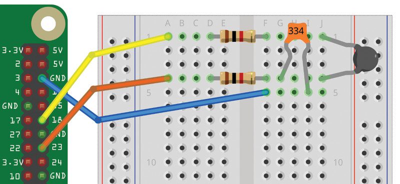
Using Figure 1 as a reference, push the jumper wires into the breadboard at the positions shown. Bend the resistor legs so that they fit into the holes.
The five holes in each row on the breadboard are connected together under the plastic, so it’s very important to get the correct row for your component leg. In this project, none of the components needs to be a particular way around.

Connect breadboard to Raspberry Pi
Again, using Figure 1 as a reference, connect the GPIO pins on Raspberry Pi to the breadboard. A GPIO template will make this easier – if you don’t have one, you’ll need to carefully count the pin positions. It doesn’t matter what colour jumper wires you use, but if you stick to the colours used in the diagram, it’s easier to check that your wiring is correct. Running the program
Load and run the 05_thermometer.py program using Mu.
# 05_thermometer.py
# From the code for the Box 1 kit for the Raspberry Pi by MonkMakes.com from PiAnalog import *
from guizero import App, Text
import time p = PiAnalog() # Update the temperature reading
def update_temp(): temperature = p.read_temp_c() temperature = "%.2f" % temperature # Round the temperature to 2 d.p. temp_text.value = temperature temp_text.after(1000, update_temp) # Create the GUI
app = App(title = "Thermometer", width="400", height="300")
Text(app, text="Temp C", size=32)
temp_text = Text(app, text="0.00", size=110)
temp_text.after(1000, update_temp) # Used to update the temperature reading
app.display()
The code is configured for the thermistor supplied with the MonkMakes Project Box 1 kit. If you look near the top of the file, you will see the line:
temperature = p.read_temp_c().
If you are using your own thermistor, you will need to add two new parameters to the method call. The first parameter is the value of Beta for the thermistor, and the second the value to R25 (resistance at 25°C). You will find both of these values in the thermistor’s datasheet. For example, if Beta is 3800 and R25 is 1 kΩ, you would use: p.read_temp_c(3800, 1000).
After a few seconds, a window will appear, like the one in Figure 2, displaying the temperature. If you would rather have the temperature displayed in degrees Fahrenheit, then run the program 05_thermometer_f.py instead.

Changing the temperature
The easiest way to change the temperature of the thermistor is to pinch it between your fingers so that your body warmth heats it up. You should see the temperature steadily increase and then decrease back to room temperature when you let go of the thermistor.
Light meter project
: Disconnect the breadboard
This project has almost the same layout as the thermometer, and we are just going to swap the thermistor for a phototransistor, but it is still a good idea to disconnect the breadboard from your Raspberry Pi. First, pull the jumper wires off the GPIO pins on Raspberry Pi and then take the thermistor off the breadboard.
Place phototransistor onto breadboard
This time, using Figure 3 as a guide, put the phototransistor legs into the breadboard. The phototransistor must go the correct way around: the longer leg should go to row 4.

Connect breadboard to Raspberry Pi
Using Figure 3 as a reference, connect the GPIO pins on Raspberry Pi to the breadboard using three female-to-male jumper wires.
Running the program
To use the light meter, load and run the program 08_light_meter.py in Mu.
# 08_light_meter.py
# From the code for the Box 1 kit for the Raspberry Pi by MonkMakes.com from guizero import App, Text
from PiAnalog import *
import time, math p = PiAnalog() def light_from_r(R): # Log the reading to compress the range return math.log(1000000.0/R) * 10.0 # group together all of the GUI code
# Update the reading
def update_reading(): light = light_from_r(p.read_resistance()) reading_str = "{:.0f}".format(light) light_text.value = reading_str light_text.after(200, update_reading) app = App(title="Light Meter", width="400", height="300")
Text(app, text="Light", size=32)
light_text = Text(app, text="0", size=110)
light_text.after(200, update_reading)
app.display()
When the program starts, a window like that in Figure 4 will appear, showing the light level. Try shading the phototransistor with your hand or shining a light on it to see how the readings change.

Schreibe einen Kommentar
Du musst angemeldet sein, um einen Kommentar abzugeben.