Schlagwort: Uno
-

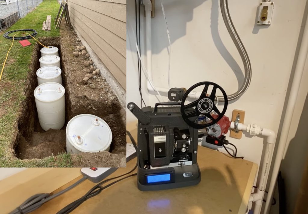
Homemade thermal battery system keeps the shop cool with Arduino
Reading Time: 2 minutesArduino Team — January 3rd, 2022 When trying to cool off a space, most people reach for an air conditioning unit that uses a pump, compressor, refrigerant, and a radiator to move heat from inside a room to the outside air. But in a break from this typical model, YouTuber Curtis in…
-

This gear turns only once every 346 quintillion years
Reading Time: 2 minutesArduino Team — December 31st, 2021 Mechanical advantage is the single most important principle in mechanical engineering. Archimedes is quoted as saying “Give me a lever long enough and a fulcrum on which to place it, and I shall move the world.” We could say the same of gear reductions, but they…
-

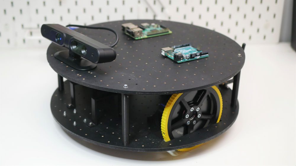
Nikodem Bartnik created a powerful robotic chassis using T-Motor AK series actuators and Arduino
Reading Time: 2 minutesArduino Team — December 28th, 2021 After attempting to incorporate a few AK80-9 actuators from T-Motor into a robotic arm project, YouTuber Nikodem Bartnik was forced to pivot to a different kind of project: a universal robotic chassis/platform. By using these high-power and high-precision motors, his robot could be both fast and accurate while moving along…
-

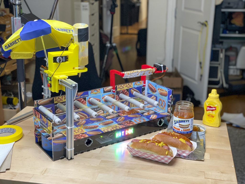
Becky Stern’s machine brings the NYC hot dog experience to you
Reading Time: 2 minutesBecky Stern’s machine brings the NYC hot dog experience to you Arduino Team — December 24th, 2021 For her gift to Colin Furze as a participant in this year’s YouTube Makers Secret Santa event, Becky Stern opted to bring the street food of New York City in the form of a mostly automatic hot dog dressing machine.…
-
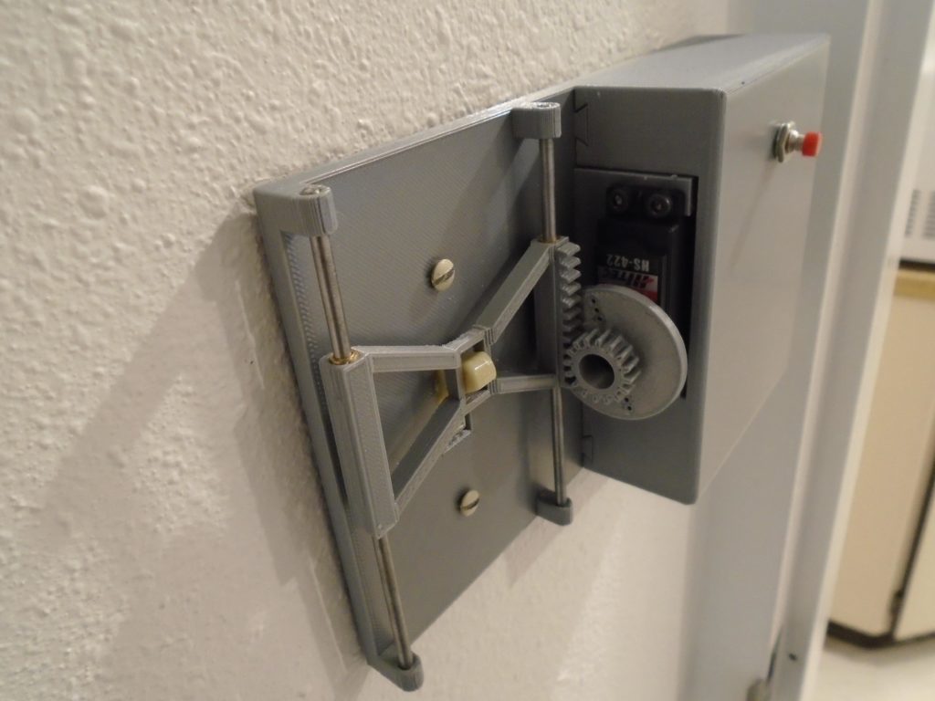
Retrofit your light switch with this remote-controlled device
Reading Time: 2 minutesArduino Team — December 23rd, 2021 It can be extremely annoying and frustrating to finally get comfortable somewhere only to realize that you forgot to turn off a light, thus requiring a short journey to and from the wall switch. Mechanical engineering student and Instructables user alanmerritt ran into the same problem in his…
-

Small-scale autonomous boat made out of recycled water bottles and a Tupperware container
Reading Time: 2 minutesArduino Team — December 16th, 2021 As part of their city’s beach restoration project, Instructables users Kousheek Chalraborty and Satya Schiavvina, who go by the team name Technovation, needed to construct a small and cheap boat that could assist in mapping the depth of the sea floor at various locations. The design they were…
-
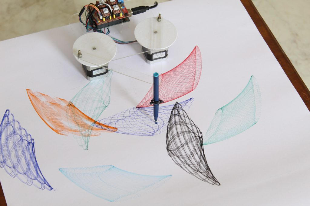
Produce pretty patterns with this Arduino-powered project
Reading Time: 2 minutesArduino Team — December 15th, 2021 Oftentimes, even the simplest of machines can produce intricate results, and that is perhaps best demonstrated by Instructables user Dee et Ko and their pattern making device. Reminiscent of a Spirograph, it consists of just a few parts — two stepper motors, an Arduino Uno, a motor shield, and…
-

One board to rule them all: History of the Arduino UNO
Reading Time: 10 minutesAs familiar as we all are with the UNO, there’s probably a lot you don’t know about the iconic Arduino microcontroller board. Put on your rose-tinted spectacles, and let’s wax poetic about the origins of this beloved maker board. Rise of the Techno-Hippies By 2009, the team that would become Arduino was…
-

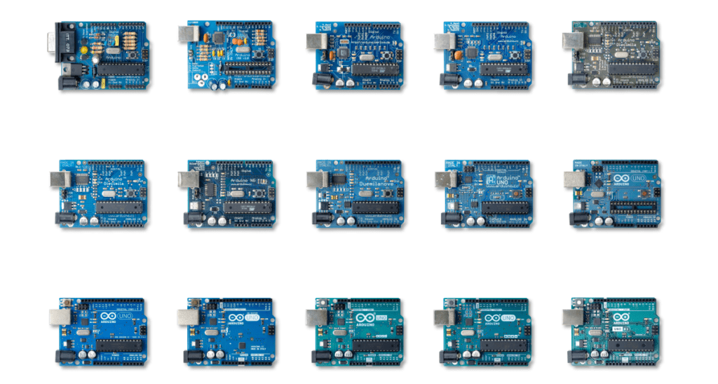
Our 12 favorite Arduino UNO projects
Reading Time: 3 minutesThe UNO wasn’t Arduino’s first board, and it won’t be its last. There have been many varieties of microcontroller and maker boards before and after the UNO, but none have been as iconic. As we cross the epic milestone of 10 million UNOs sold and the launch of the UNO Mini Limited…
-

Introducing the Arduino UNO Mini Limited Edition: Pre-orders now open
Reading Time: 3 minutesThe iconic Arduino board is back, in the shape of the UNO Mini Limited Edition. Pre-orders have just gone live, so don’t dawdle if you want to get your hands on this stunning piece of Arduino history. 10 Million Makers Can’t Be Wrong The UNO Mini Limited Edition is here to celebrate…
-

Meet RobBob, a 3D-printed robot head that works with an N64 controller
Reading Time: 2 minutesArduino Team — November 23rd, 2021 Inspired by a special two-axis mechanism that uses a pair of beveled gears to create panning and tilting motions, maker and YouTuber JBV Creative wanted to integrate it into a larger kinetic sculpture that could move electromechanically while also looking great at the same time. This led to…
-

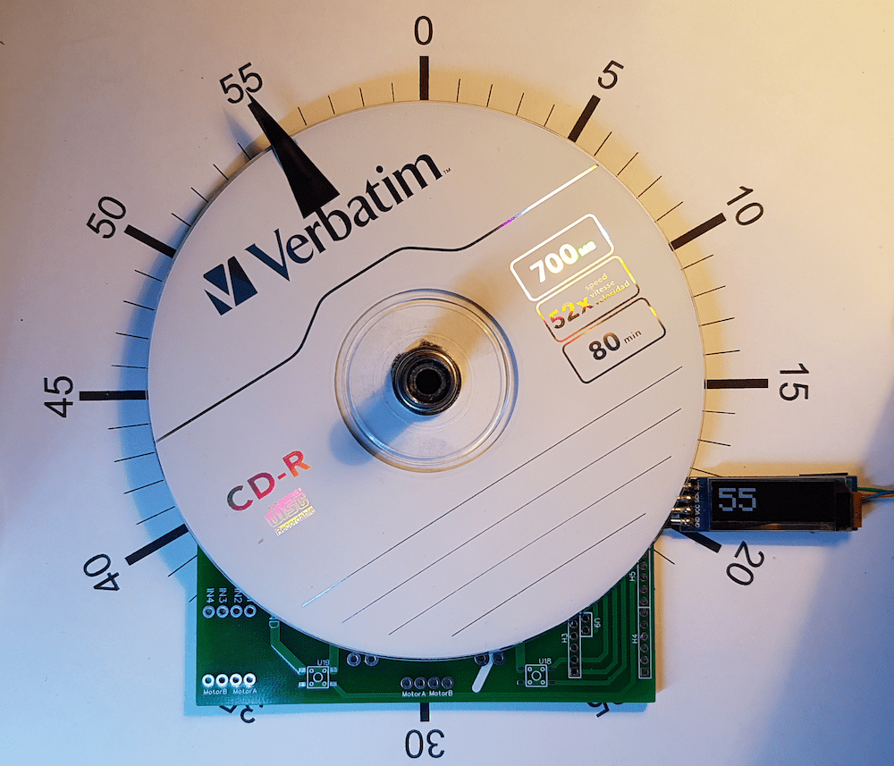
Time to put this DIY absolute position encoder to work as a clock
Reading Time: 2 minutesArduino Team — November 10th, 2021 Being able to derive the absolute position of an object is vital in countless applications, primarily for anything that uses a motor. Instructables user holybaf had the idea to build their own rotary encoder, which has 60 degrees of resolution and utilizes a CD to act as a precise…
-

James Bruton built a robot that moves like an earthworm
Reading Time: 2 minutesArduino Team — November 10th, 2021 Self-propelling robots come in a whole host of shapes, sizes, and capabilities, with some being able to fly while other can walk on just a couple or many legs. But YouTuber James Bruton wanted to innovate on this concept even further by designing and building a robot that mimics an…
-

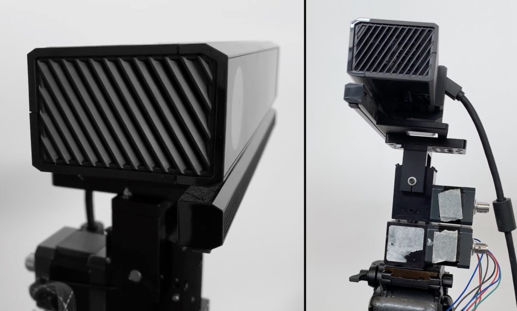
FarOut extends the range of Kinect-based touch sensing
Reading Time: 2 minutesArduino Team — November 10th, 2021 Capacitive touchscreens today use a digitizer to pinpoint the coordinates of a finger tap. That makes sense for smartphones and tablets, but isn’t ideal for large scale applications. If you want to recognize touches on the scale of an entire wall, a Kinect sensor could be…
-

This MP3 player is controlled with a twirl of your finger and wave of your hand
Reading Time: 2 minutesArduino Team — November 9th, 2021 The classic MP3 player was a truly innovative device for its time, however with the advent of modern smartphones and other do-it-all gadgets, they have largely fallen by the wayside. In order to add a new twist, Norbert Zare decided to implement an MP3 player that not only responds to…
-

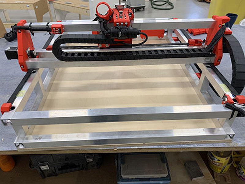
Learn how to build your own massive 3D-printed CNC router
Reading Time: 2 minutesArduino Team — November 3rd, 2021 3D printers are very popular in the maker community and CNC machines complement them well. While 3D printers fabricate parts by adding material over time, CNC mills and routers fabricate parts by subtracting material. That is preferable when working with large parts or when you require…
-

Scale up your dragon costume with wings that extend, flap and retract
Reading Time: 2 minutesArduino Team — November 1st, 2021 This year for Halloween, Quint BUILDs wanted to make something special for his daughter’s costume. Quint’s idea was to design and fabricate a pair of mechatronic dragon wings that can mount to a user’s back and move in three different modes by utilizing a set of pneumatic air cylinders. …
-

YouTuber Shane Wighton built a robot that paints murals
Reading Time: 2 minutesArduino Team — November 1st, 2021 Driven by a desire to print massive pieces of art on his new studio’s blank wall, Shane Wighton of the YouTube channel Stuff Made Here set out to create a large painting robot, which he calls “Janksy” after the famous artist and the jankiness of the construction. In principle,…
-
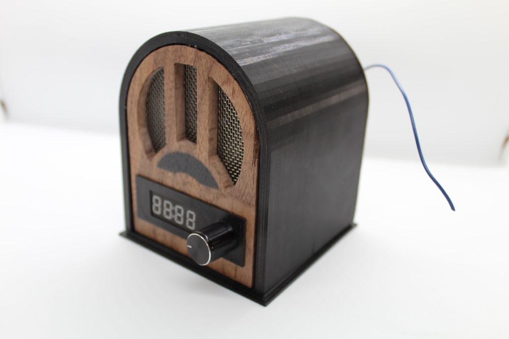
This Arduino radio looks like something from 100 years ago
Reading Time: 2 minutesArduino Team — October 20th, 2021 As time has progressed, personal radios have shrunk from the size of a large filing cabinet down to a tiny circuit that can be integrated into other ICs. Instructables user exposedwire wanted to bring back the experience of a vintage 1920s radio set, so they built one out of…
-
Duco is a wall-climbing robot that paints circuit murals
Reading Time: 2 minutesArduino Team — October 6th, 2021 When we think of circuits, we tend to picture wires or PCB traces. But a circuit is anything that conducts electricity between components. Today we have more options than ever before thanks to material like conductive ink and thread. Utilizing conductive ink on a large scale,…
-
Flingbot is a robot that flings paint at a canvas to create art
Reading Time: 2 minutesArduino Team — September 20th, 2021 Jackson Pollock was famous for his unique style of splattering large blobs of paint across a canvas, and it was this technique that JBV Creative was trying to imitate. But rather than working by hand to painstakingly dip a brush into paint and then flinging it many times…