Schlagwort: Uno
-

This reverse geocache gift box only opens at specific GPS coordinates
Reading Time: 2 minutesGeocaching is a hobby that combines the fun of a scavenger hunt with modern GPS technology. One party will hide a small cache somewhere, then post the general location and the exact GPS coordinates for other parties to find. The goal is to use GPS navigation to find the hidden cache. Often,…
-

This train of trash bins moves to the curb with the press of a button
Reading Time: 2 minutesOnce a week, millions of people set out their trash cans next to the curb for collection the following day, which many consider to be extremely annoying or laborious. So rather than manually dragging out the garbage and recycling bins, the YouTuber known as Max Maker decided to build a system that…
-

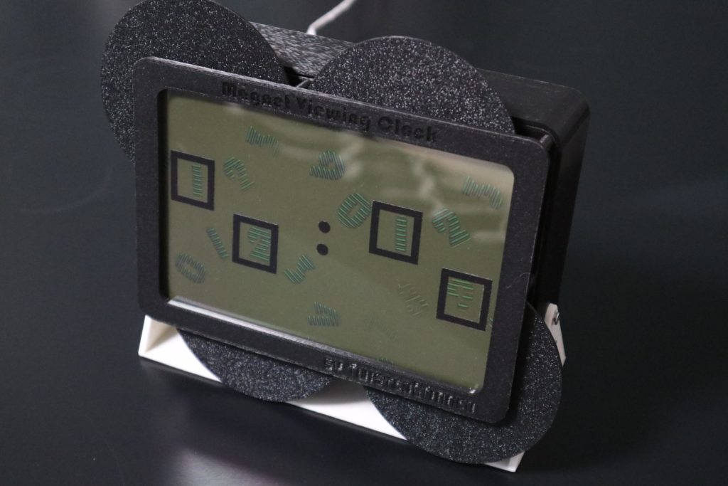
This clever clock displays the time in magnetic fields
Reading Time: 2 minutesYou’ve probably seen videos of people moving magnets near iron dust, which results in the dust aligning itself to the patterns created by the magnetic fields. Magnetic viewing film works the same way, but with the dust in an oil suspension sitting in the gap between two sheets of transparent plastic. By…
-

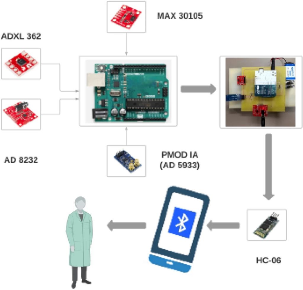
This health belt can provide early warning of heart failure
Reading Time: 2 minutesHeart disease is the most common cause of death — not just in industrialized countries, but for the world as a whole. Many deaths caused by heart failure could be prevented if the patient received medical care sooner, but people are often unaware of impending heart failure until it actually occurs. However,…
-

See how Ben Eater reverse engineered an ’80s TV-censoring device
Reading Time: 2 minutesBack in the 1980s, there existed a piece of hardware called the “TVGuardian,” which would attempt to censor incoming video in real-time. As recently covered by the wonderful YouTube channel Technology Connections, the TVGuardian reads captioning data as it’s sent and then replaces the bad word(s) with an alternative phrase and also mutes…
-

Build your own coffee roaster out of a hot air popcorn popper
Reading Time: 2 minutesGreen (unroasted) coffee beans cost about half as much as their roasted counterparts. By purchasing green coffee beans, you can save quite a bit of money in the long term. Roasting your own coffee beans also gives you much greater control over the flavor profile and caffeine content of your coffee (caffeine…
-

Computer vision and project mapping enable AR PCB debugging bliss
Reading Time: 2 minutesImagine if you could identify a component and its schematic label by simply touching that component on your PCB. Imagine if you selected a pin in KiCAD and it started glowing on your real, physical PCB so you can find it easily. Imagine if you could see through your PCB’s solder mask…
-

Are you ready to go back to the future?
Reading Time: 3 minutesArduino Make Your UNO Kit is finally here The first Arduino UNO was launched back in 2005, with a clear purpose to allow everyone who had an idea to make it possible through a simple and open interface. Many years have passed, technology has evolved, but we never forgot that initial thrill…
-

Making a puppet ride an RC tricycle
Reading Time: 2 minutesInspired by a remote-controlled Radio Flyer tricycle in which Kermit pedaled around at Maker Faire New York 2018, Donald Bell wanted to create his own version that could bring similar magic to people who interact with it. It began with the same Radio Flyer tricycle as in the original video, except this one was modified a…
-

This jack-o’-lantern farts pumpkin spice whenever someone gets close
Reading Time: 2 minutesHalloween is just a week away and that means two things: jack-o’-lanterns decorating front stoops around the world and the sudden proliferation of pumpkin spice-based products. Pumpkin spice isn’t a spice made from pumpkin, but rather a spice used in pumpkin pies. As we all know, farmers harvest pumpkin spice from pumpkin…
-

Plumbing valves make great heavy duty analog inputs
Reading Time: 3 minutesMost of your Arduino projects will require inputs and buttons are always the obvious choice. But most of the buttons and switches on the market meant for low-voltage DC projects are quite delicate. That makes them unsuitable for applications that need to withstand heavy-handed use. YouTuber Alistair Aitchison of Playful Technology designs…
-

Stranger Things Christmas lights are the perfect Halloween decoration
Reading Time: 2 minutesIn the first season of Stranger Things, a character uses a string of Christmas lights to communicate with a missing loved one. The missing person in question can flash particular lights next to letters painted on a bedsheet to spell out messages. The Christmas lights and bedsheets have become a part of pop…
-

Flux is a kinetic art installation brought to life with Arduino
Reading Time: 2 minutesArt may be subjective, but all of our readers can appreciate the technology that goes into kinetic art. That term encompasses any piece of art that incorporates movement, which means it can be as simple as a sculpture that turns in the wind. But by integrating electronics, artists can achieve impressive effects.…
-

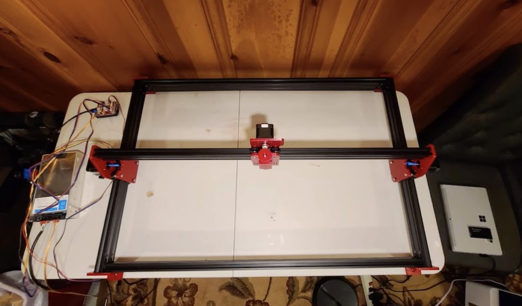
Mokey is an affordable DIY laser engraver
Reading Time: 3 minutesAll makers love lasers and they make great shop tools. Even low-power lasers can engrave a variety of materials. Cutting material requires more power, with the most popular cutting lasers being CO2 with power between 10W-100W. But the small, affordable solid state laser modules can cut some materials, like acrylic, if you…
-

Build your own automatic bean sprouter for superfood meals
Reading Time: 2 minutesArduino Team — September 13th, 2022 Mung bean sprouts are a very popular food throughout Asia, as they are nutritious and extremely easy to grow. While you can certainly purchase these bean sprouts at your local markets, you can also take advantage of their easy cultivation to grow your own. Doing so…
-

Automating precise welds with an Arduino
Reading Time: 2 minutesArduino Team — September 5th, 2022 Welding is a skill that takes years to perfect, and yet consistently placing a TIG welder in exactly the right spot many times over is nearly impossible. To assist with this process, a few of element14 Presents host Kaleb Clark and his company’s clients had constructed two rigs…
-

An Arduino controls this strange two-wheel steering e-bike
Reading Time: 2 minutesArduino Team — August 24th, 2022 James Bruton loves to experiment with unusual vehicle drive systems and configurations to find out how they perform under the dynamic conditions of real-world use. Internal combustion engines and driveshafts don’t tend to fit in those vehicles, so Bruton often utilizes electric motors. He usually turns…
-
Back to the Future remote shows real DeLorean speed
Reading Time: 2 minutesArduino Team — August 18th, 2022 In the Back to the Future films, the iconic DeLorean time machine had to reach 88mph in order to jump forward or backward in time. Even in 1985, it wasn’t very hard for a family sedan to reach 88mph, but that’s not the point. To show viewers the…
-

A wearable, waterproof, wireless human-machine interface
Reading Time: 2 minutesArduino Team — August 10th, 2022 “Human-machine interface” (HMI) is a general term that describes any physical input or output hardware that people can use to interface with systems (like computers) and vice versa. That very broad definition usually applies to computer input devices like keyboards or output devices like monitors. The…
-

Affordable CAT scan machine built with an Arduino
Reading Time: 2 minutesArduino Team — August 9th, 2022 A CT (computed tomography), or CAT (computed axial tomography), scan is a type of medical imaging technique in which multiple X-ray “slices” come together to form a pseudo-3D model. CT scanners are the kinds of medical equipment that are so expensive that manufacturers don’t even bother…
-

LEGO-firing turret targets tender tootsies
Reading Time: 2 minutesArduino Team — August 4th, 2022 Stepping on LEGO bricks is a meme for a reason: it really @#$%&! hurts. LEGO brick design is ingenious, but the engineers did not consider the ramifications of their minimalist construction system. We’ve seen people do crazy things for Internet points, such as walk across a…