Schlagwort: Uno
-

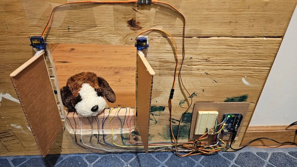
This DIY pet door helps keep a dog out of the cat’s litter box
Reading Time: 2 minutesScience Buddies had a problem: their tiny little pug loves eating their cat’s poop. Because the pug is smaller than the cat, they couldn’t simply put the litter box behind a tiny cat door. So they came up with a more sophisticated solution: a motorized door triggered by a magnetic collar. Riley…
-

This robot dominates dart games
Reading Time: 2 minutesYou’ll find dartboards in just about every dive bar in the world, like cheaper and pokier alternatives to pool. But that doesn’t mean that darts is a casual game to everyone. It takes a lot of skill to play on a competitive level and many of us struggle to perform well. Niklas…
-

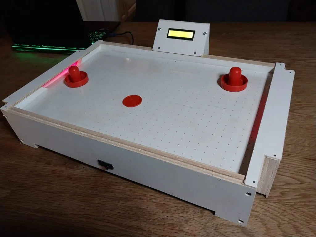
This small scorekeeping air hockey game brings the arcade classic to your tabletop
Reading Time: 2 minutesGo to any arcade and the air hockey table will probably be one of the most popular games they have. Everyone loves air hockey, but a lot of people don’t want to go to an arcade just to play. If you fall into that category, then you can follow LloydB’s Instructables guide…
-
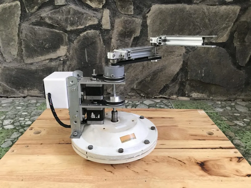
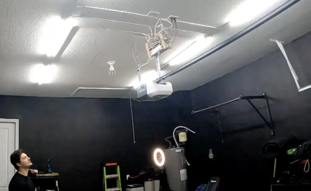
Ceiling fan becomes a “spaceship” SCARA robot arm
Reading Time: 2 minutesWe all know how annoying a ceiling fan can be when it isn’t balanced well and that annoyance perfectly demonstrates the necessity of a good, sturdy bearing. A ceiling fan’s bearing needs to allow for smooth rotational motion with as little friction as possible, while completely constraining movement in every other axis.…
-

A delightful Chandrayaan-3 rocket launch model
Reading Time: 2 minutesIt may not get as much attention as NASA, Roscosmos, or even CNSA (China National Space Administration), but India’s space program has achieved some impressive goals. Just last year, in August of 2023, ISRO (Indian Space Research Organisation) completed their first soft landing on a celestial object with the Chandrayaan-3’s moon landing.…
-
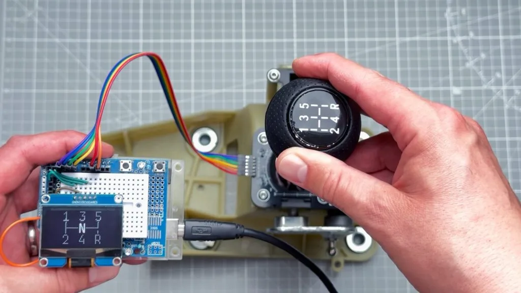
An easy way to add a gear indicator for your stick shift
Reading Time: 2 minutesThe objective benefits may be almost nonexistent today, but there is still something satisfying about rowing through the gears in a car with a manual transmission. If that car was made in the past couple of decades, there is a good chance that it has an indicator on the dash to tell…
-

Autochef-9000 can cook an entire breakfast automatically
Reading Time: 2 minutesFans off Wallace and Gromit will all remember two things about the franchise: the sort of creepy — but mostly delightful — stop-motion animation and Wallace’s Rube Goldberg-esque inventions. YouTuber Gregulations was inspired by Wallace’s Autochef breakfast-cooking contraption and decided to build his own robot to prepare morning meals. Gregulations wanted his Autochef-9000 to…
-

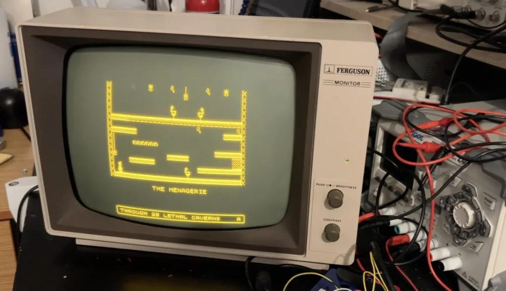
This new game engine runs Manic Miner on an Arduino UNO
Reading Time: 2 minutesFor owners of Sinclair ZX Spectrum computers in the ‘80s, few games were more desirable than Matthew Smith’s Manic Miner. It is very much a classic and has official and unofficial ports available for just about every console and computer released since. There was even a port made for Microsoft’s Zune MP3…
-

This animatronic CatNap is predictably creepy
Reading Time: 2 minutesPoppy Playtime is an interesting horror video game — or rather, an episodic series of games — that puts players into the eerie toy factory of fictional company Playtime Co., where they find that the company’s characters are alive and quite aggressive. A big part of the game’s appeal is the creepy character…
-

Getting more realistic camera movements in VR with an Arduino
Reading Time: 2 minutesIn virtual reality, anything is possible, yet being able to accurately model things from the real-world in a digital space remains a huge challenge due to the lack of weight/feedback that would otherwise be present in physical objects. Inspired by working with digital cameras and the inherit imperfection they bring to their…
-

The Hardware-Oriented Microprocessor Simulator illustrates the inner workings of microcontrollers
Reading Time: 2 minutesDo you really understand what is happening within the mysterious black packaging of a microcontroller or microprocessor? Most people don’t — we just learn how to use them. That’s because they’re wildly complex circuits combining many different subsystems that are all abstracted away from the view of the user. To help students better understand…
-

Upgrade your shop with voice-controlled smart LED lighting
Reading Time: 2 minutesCongratulations! You finally have a garage to call your own and you’re ready to turn it into the workshop of your dreams. But before you go on a shopping spree in Home Depot’s tools section, you may want to consider upgrading from that single dim lightbulb to more substantial lighting — otherwise,…
-

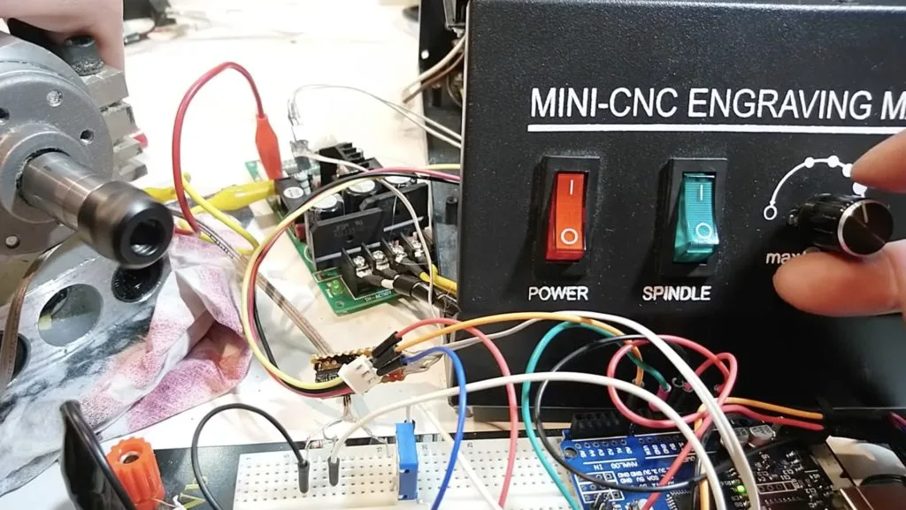
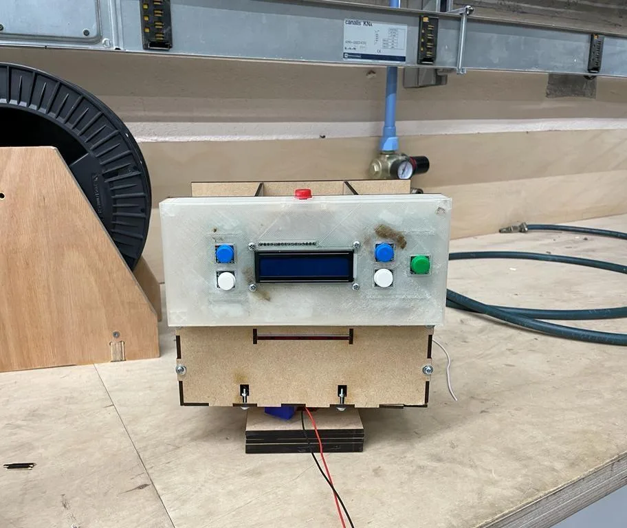
Build a better spindle controller for your CNC mill
Reading Time: 2 minutesProper spindle speed control is necessary to get good CNC milling results. If your spindle speed is inconsistent, your speed and feed calculations will be wrong. That will lead to poor finishes and even broken end mills (and ruined parts) in extreme cases. But cheap CNC mills and routers often have insufficient…
-
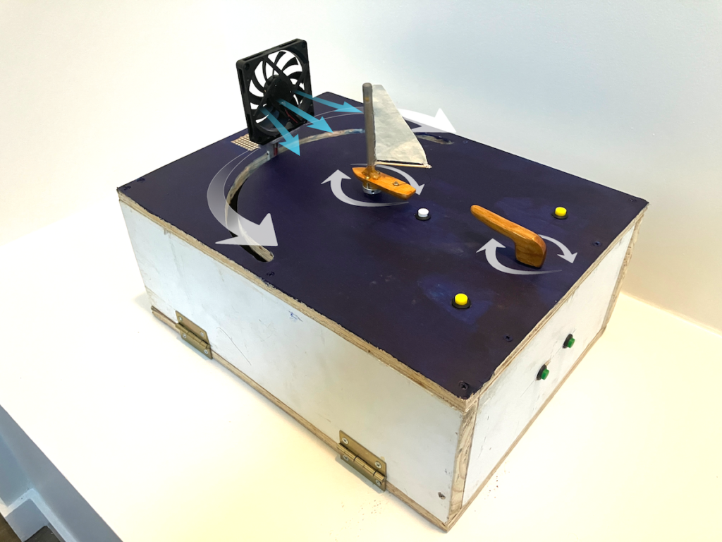
Tabletop device teaches you the basics of sailing before hopping on board a real boat
Reading Time: 2 minutesSailing is a great way to get outdoors and explore the open waters, yet it can also pose some risks to the pilot and passengers if they are unfamiliar with how the boat handles under different wind conditions. As Kif Scheuer notes in his project write-up, traditional instruction relies on simple 2D illustrations,…
-
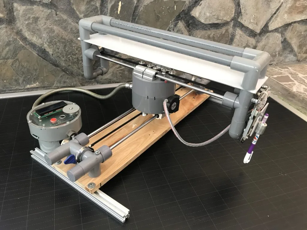
Affordable fixed-belt CNC plotter runs on Arduino
Reading Time: 2 minutesDesign paradigms are the norm in every industry and automated machine tools aren’t any different. Most 3D printers, for example, function in a similar way: each axis rides on rails, with belts pulled by fixed motors. Pen plotters tend to utilize similar kinematics. But sometimes we see builds that ignore established paradigms,…
-

This automated machine shuffles and deals cards so you don’t have to
Reading Time: 2 minutesShuffling and dealing is very serious business when you’re playing any card game that puts money on the line, like poker. Even when the stakes aren’t that high, poor shuffling or dealing can drive a family apart. If you’re tired of being criticized for your card-handling skills, maybe you should build this…
-
Transform your coffee table into a piece of kinetic sand art
Reading Time: 2 minutesLike most furniture, a coffee table should both look good and function well. To function well, a coffee table just needs a flat surface. But looking good is a lot more complicated and depends entirely on owner taste. If kinetic art is your thing, then you might consider building this automatic sand…
-

Desktop elevator provides a positive sensory experience for an autistic child
Reading Time: 2 minutesAutism often comes with a unique sensory experience that differs from that of most neurotypical people. That tends to be publicized as a negative thing, as some sensations can cause some autistic people a lot of discomfort. But the opposite can also be true, with positive sensory experiences providing great joy. The…
-

Syncing tunes to Christmas tree lights with the Arduino Opta
Reading Time: 2 minutesWe all know that one neighbor who always goes the extra mile when decorating for the holidays, and after taking inspiration from these large displays of light and sound, Marcelo Arredondo, Andres Sabas, and Andrea ZGuz of the Electronic Cats crew decided to build a smaller version for their Christmas tree using the Arduino Opta micro PLC.…
-

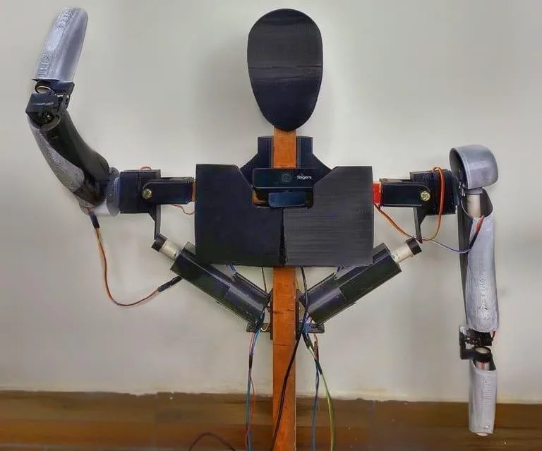
This DIY humanoid robot talks back to you
Reading Time: 2 minutesMost people with an interest in robotics probably dream of building android-style humanoid robots. But when they dip their toes into the field, they quickly learn the reality that such robots are incredibly complex and expensive. However, everyone needs to start somewhere. If you want to begin that journey, you can follow…
-

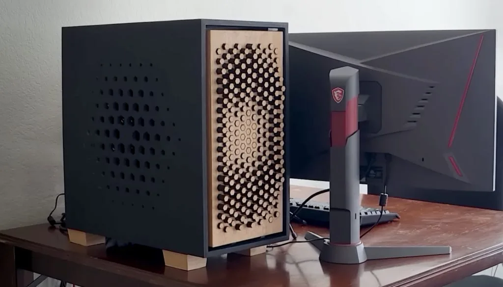
DIY PC case features interchangeable kinetic front panels
Reading Time: 2 minutesRGB LEDs are sooooo 2015 and the “it” thing today is kinetic art. If a blinking LED is the “hello world” of the microcontroller industry, then making something move is the equivalent of finally fingering out how pointers work. So Robert of the Ideal Idea YouTube channel had to learn a lot…
-

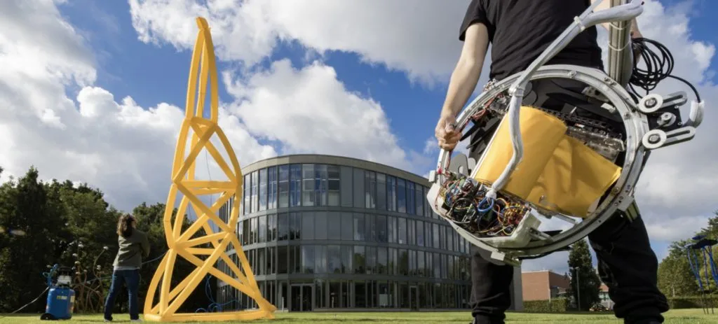
This machine automatically fabricates inflatable truss structures
Reading Time: 2 minutesHow does a flat sheet of material, like plastic or an airtight textile, become an inflatable structure with a three-dimensional shape? The traditional process involves creful design with a lot of trial and error in order to place seams between two or more sheets. That involves a lot of labor, so a…