Schlagwort: Uno

  • Ping pong ball bounces forever under Arduino control

    Ping pong ball bounces forever under Arduino control

    Reading Time: < 1 minute

    Ping pong ball bounces forever under Arduino control

    Arduino TeamJuly 25th, 2018

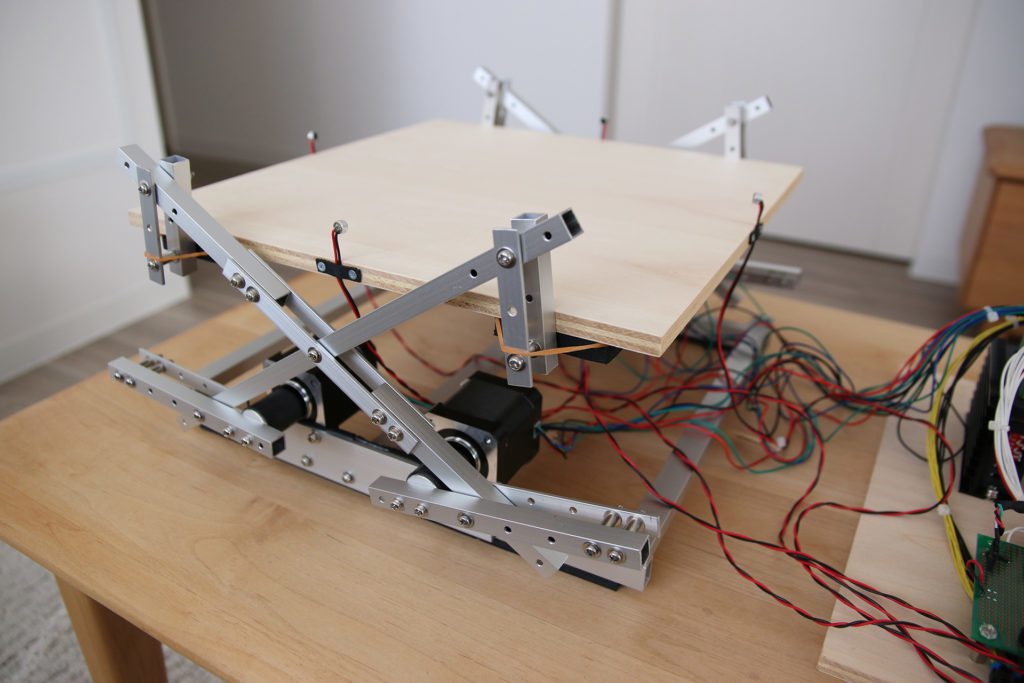
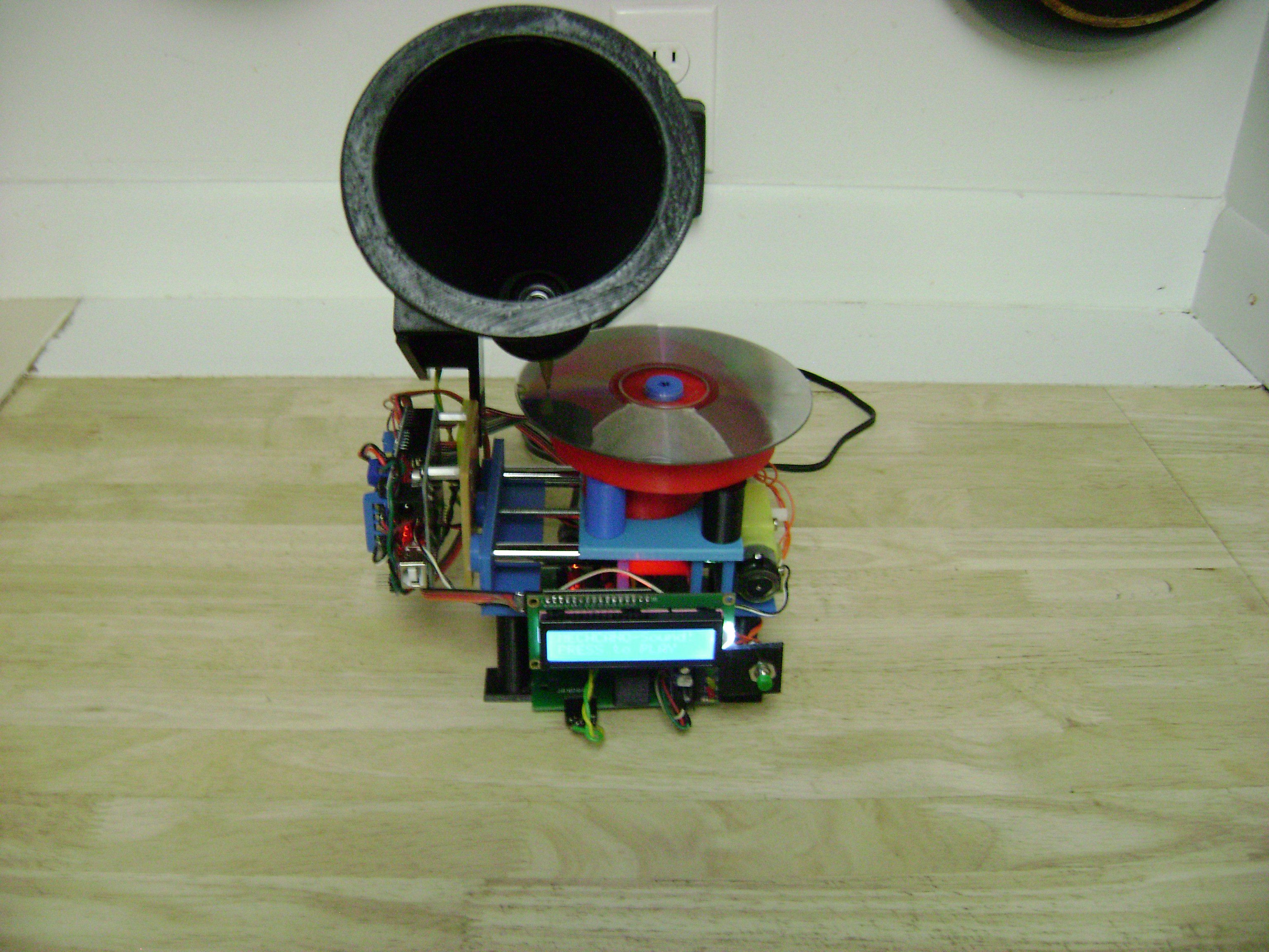
    As spotted on Reddit, maker “tkuhn” of Electron Dust decided to create a machine “with the sole goal of keeping a ping pong ball bouncing for as long as possible.” 

    To accomplish this, he turned to audio feedback using the time difference between when four electret microphones sense the sound of the bouncing ball. Audio processing is accomplished with the help of a simple flip-flop circuit, while an Arduino Nano is used to reset it after each cycle.

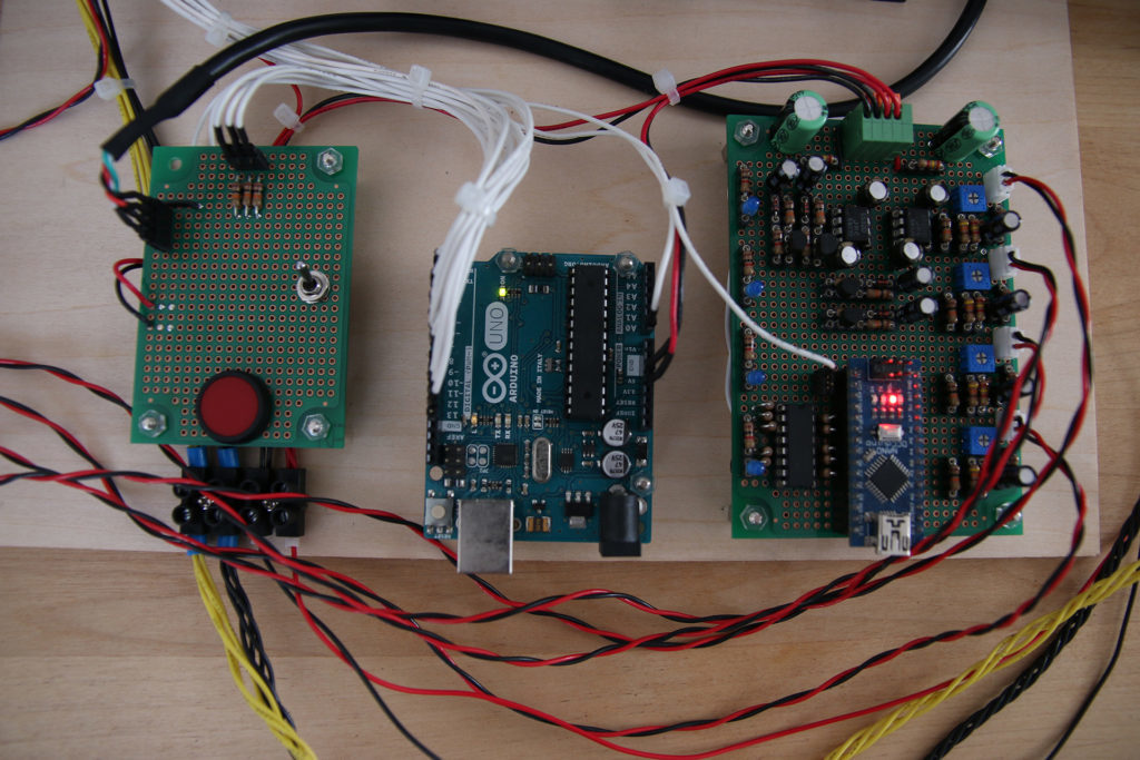
    Data is then passed along to an Arduino Uno, which employs four steppers motors/drivers and a linkage system to keep the ball in play. This impressive setup can be seen in the video below, and code is available on GitHub.

    [youtube https://www.youtube.com/watch?v=0WiGiJk03Q8?feature=oembed&w=500&h=281]

    Website: LINK

  • imPulse is an energy harvesting alternative for bicycles

    imPulse is an energy harvesting alternative for bicycles

    Reading Time: 2 minutes

    imPulse is an energy harvesting alternative for bicycles

    Arduino TeamJuly 16th, 2018

    Javier Betancor is developing a system that collects power as you ride a bike, with the goal of powering data collection and lighting. “imPulse” uses a stepper motor for power generation, along with a geared hub to make the motor spin at multiples of the wheel speed.

    While the project is still a prototype, the headlights and rear lighting assemblies already look very good, and CAD files as well as Arduino code are available here.

    The aim of this project is to provide a cost-effective alternative to power generation on bikes using conventional stepper motors while adding other capabilities, such as: 

    – An integrated data logging system to monitor power generated on each trip.

    – A smart lighting system with addressable LEDs, working as indicators, braking lights and headlights, incorporating Light Dependant Resistors (LDRs) to sense the environment and to reduce the risk of glare.

    – Power Distribution Board (PDB) to charge two different/generic powerbanks. While one powerbank is charged, the other one is used to supply energy to the system.

    You can see a prototype of the lighting system in the video below, using an Arduino Uno for control as a turn signal and brake light, as well as a constant beam for visibility. Find additional information and follow along with Betancor’s progress in his Hackaday log. 

    [youtube https://www.youtube.com/watch?v=0edCI_3f-R0?feature=oembed&w=500&h=281]

    Website: LINK

  • Stepper motor utilized as a rotary encoder with Arduino

    Stepper motor utilized as a rotary encoder with Arduino

    Reading Time: < 1 minute

    Stepper motor utilized as a rotary encoder with Arduino

    Arduino TeamJuly 16th, 2018

    Stepper motors work by alternating a series of magnets in order to rotate its shaft by a certain angle. When the shaft is manually twisted, these magnets produce an electrical signal in a predictable pattern, which as shown in the video below, can be used as an encoder with the help of an Arduino Uno.

    More information, including a circuit diagram and the Arduino code used for the stepper-NeoPixel and stepper-stepper examples can be found here. While the write-up notes that this stepper-encoder won’t work reliably if turned too slowly, it seems to work quite well at the fairly low speed shown in the demonstrations.

    I want to tell you how to make incremental encoder from stepper motor. When we turning shaft of stepper motor it works like generator. It generates certain impulses on its coils. After some signal processing, we get same impulses as incremental encoder. This encoder has one problem, it can drop steps if you turning very slowly. But for many applications, it doesn’t matter.

    [youtube https://www.youtube.com/watch?v=fQ19661UGx8?feature=oembed&w=500&h=281]

    Website: LINK

  • Dual ultrasonic sensors combine for 2D echolocation

    Dual ultrasonic sensors combine for 2D echolocation

    Reading Time: 2 minutes

    Dual ultrasonic sensors combine for 2D echolocation

    Arduino TeamJuly 13th, 2018

    Ultrasonic sensors are great tools for measuring linear distance or object presence. As shown in this experiment by “lingib,” two sensors can also be combined to determine not just linear distance to a sensor, but its position in an X/Y plane.

    For his experiment, he hooked two of these units up to an Arduino Uno at a known distance from each other, with one emitter blanked out with masking tape. The non-blanked emitter pulses an ultrasonic signal, which is bounced back to it as well as the second sensor by the measured object. From the time it takes to receive the return signal, distance to each sensor can be inferred, giving a triangle with each side known. Trigonometry is then used to pinpoint the item’s position, and a Processing sketch displays coordinates on lingib’s computer.

    This Instructable explains how to pinpoint the location of an object using an Arduino, two ultrasonic sensors, and Heron’s formula for triangles. There are no moving parts.

    Heron’s formula allows you to calculate the area of any triangle for which all sides are known. Once you know the area of a triangle, you are then able to calculate the position of a single object (relative to a known baseline) using trigonometry and Pythagoras.

    The accuracy is excellent. Large detection areas are possible using commonly available HC-SR04, or HY-SRF05, ultrasonic sensors.

    Construction is simple … all you require is a sharp knife, two drills, a soldering iron, and a wood saw.

    [youtube https://www.youtube.com/watch?v=R1r_Ga148gw?feature=oembed&w=500&h=375]

    Website: LINK

  • Camera questions user, saves photographic response

    Camera questions user, saves photographic response

    Reading Time: 2 minutes

    Camera questions user, saves photographic response

    Arduino TeamJuly 12th, 2018

    Cultural probes aim to elicit unique responses by asking people to respond to a question, many times in the form of a photograph. While disposable cameras once worked quite nicely for this purpose, their relative rarity today meant a new digital alternative was needed. For this, Interaction Research Studio came up with a series of ProbeTools that anyone can make and customize.

    The most basic type in this series of cameras is known as the TaskCam, which features a 3D-printed frame and an Arduino Uno at its core. A shield with several snap-off sections provides user interface, including a trio of buttons, and a display that shows questions that are read off of a micro SD card. Users then respond to queries with photographs, saved with the corresponding question for future analysis.

    TaskCams recreate the proven Cultural Probe technique of relabelling disposable cameras with requests for pictures. The 3D Printed TaskCam is the basic workhorse of the collection, robust and flexible enough to use across multiple studies.

    The 3D Printed TaskCam has a small screen on the back that shows a scrollable list of requests for pictures. Researchers can load their own list of requests onto the camera to prepare for a study. When users take a picture, the image is tagged with the current request, and stored on a standard flash drive that can be removed for downloading.

    The casing for the 3D Printed TaskCam can be printed successfully without support materials even on low-end printers. The device requires a custom Arduino shield,  buy online at cost price, or follow the open-source plans to make yourself. Smart power management mean that two AA batteries provide more than enough power for an entire user study.

    You can find more details on ProbeTools here, as well as in Designboom’s recent article. 

    Website: LINK

  • Audio preamplifier with tiny OLED display and unique case

    Audio preamplifier with tiny OLED display and unique case

    Reading Time: 2 minutes

    Audio preamplifier with tiny OLED display and unique case

    Arduino TeamJuly 11th, 2018

    As spotted here, Sam Izdat decided to make a preamplifier for a friend who provides voice talent for audiobooks and the like. The primary audio circuitry for the build is provided by a purchased PCB based on the INA217 chip from TI, but from there things get a bit more interesting.

    To complete the project, Izdat added a tiny Arduino-powered OLED display. This shows a VU meter, along with a variety of other animations, seen through a window in the enclosure made from a broken wristwatch. 

    The device was prototyped using an Arduino Uno, while a Nano was embedded in the final product, allowing everything to fit into the unique compartmentalized enclosure that he constructed.

    The amplifier is based on the Texas Instruments INA217 chip, with an Arduino Nano and 128×64 OLED display providing the visualization. [Sam] was able to find a bare PCB for a typical INA217 implementation on eBay for a few bucks (see what we mean?), which helped get him started and allowed him to spend more time on the software side of things. His visualization code offers a number of interesting display modes, uses Fast Hartley Transforms, and very nearly maxes out the Arduino.

    Website: LINK

  • Robotic Connect Four lets you play remotely

    Robotic Connect Four lets you play remotely

    Reading Time: < 1 minute

    Robotic Connect Four lets you play remotely

    Arduino TeamJuly 3rd, 2018

    In order to restore some tactile feeling to remotely-played board games, maker “lyudatan” created a pair of Arduino Uno-based Connect Four robots. 

    When a player makes a move by dropping a disc into a slot, this is recorded by an IR proximity sensor on the first board. The data is then transmitted via an Ethernet shield to a web server.

    The second board uses a stepper motor to position discs above the correct slot, and drops them using a servo motor. This process is repeated until the game is done, allowing two players to play the game at a distance.

    [youtube https://www.youtube.com/watch?v=fomDjJ11hS8?feature=oembed&w=500&h=281]

    Code for the project is available here.

    Website: LINK

  • An auto-curing chamber for SLA prints

    An auto-curing chamber for SLA prints

    Reading Time: 2 minutes

    An auto-curing chamber for SLA prints

    Arduino TeamJuly 3rd, 2018

    If you have a 3D printer, it’s probably the fused deposition modeling (FDM) type that deposits melted material onto a bed, eventually building up whatever you had in mind. Stereolithography (SLA) printers, however, work in the opposite way using light to solidify liquid material, which is then pulled out of a vat. 

    While an interesting process, one consideration is that after generating the print, materials, especially those that are biocompatible, must be left alone under the proper light and temperature conditions in order to solidify fully.

    To help with this task, makers at Fablab Irbid designed their own Arduino Uno-based “Post-Curing Box.” It features UV LEDs and a rotating platform, along with a temperature sensor for monitoring conditions. Brightness, rotation, and cure time are set with a simple user interface consisting of an LCD screen, knobs, and buttons. 

    This project not only produces ideal conditions for finished parts, but certainly helps with the temptation to poke around—especially since you can see in with its partially translucent viewing window!

    [youtube https://www.youtube.com/watch?v=90Bq80Pi2tc?feature=oembed&w=500&h=375]

    Website: LINK

  • Earth Clock brilliantly tracks the sun’s light

    Earth Clock brilliantly tracks the sun’s light

    Reading Time: 2 minutes

    Earth Clock brilliantly tracks the sun’s light

    Arduino TeamJune 25th, 2018

    While we understand that the Earth rotates to produce day and night, and tilts on its axis to vary the day’s length, how is the planet positioned in relation to the sun right now? Unless you’re well-attuned to our solar system’s rotational dance, this is difficult to visualize. To help with this, hacker “SimonRob” came up with a clock that shows how the sun shines in real-time at all points on the Earth.

    An array of LEDs provides artificial lighting for the device, which rotates a nicely painted physical globe around a daily axis, along with a much larger rotational axis that controls the Earth’s tilt. Both are controlled via stepper motors, which are in turn controlled by an Arduino Uno and a bevy of supporting electronics.

    It’s a clever concept, and a well-executed build, so be sure to check out the project write-up for more information!

    Website: LINK

  • MESOMIX is an automated paint mixing machine

    MESOMIX is an automated paint mixing machine

    Reading Time: 2 minutes

    MESOMIX is an automated paint mixing machine

    Arduino TeamJune 21st, 2018

    If you’re an artist who works with paint, getting your colors right is critical, and somewhat of an art form in itself. For those that need a little assistance, the MESOMIX paint mixing machine is here to help using four 3D-printed peristaltic pumps to pull the right amount of cyan, magenta, yellow, and black (or key) to produce your desired color.

    An Arduino Uno along with a GRBL shield is implemented to coordinate each pump’s stepper motors, and MESOMIX features a design* reminiscent of a well-built 3D-printer. 

    Are you a designer, an artist or a creative person who loves to throw colors on your canvas, but it’s often a struggle when it comes to making the desired shade.

    So, this art-tech instruction will vanish that struggle into thin air. As this device, uses off the shelf components to makes the desired shade by mixing the right amount of CMYK (Cyan-Magenta-Yellow-Black) pigments automatically, which will drastically reduce the time spent on mixing the colors or money spent on purchasing different pigments. And will provide you that extra time for your creative.

    For more information, you can check out MakerBash’s excellent project here.

    *Frame parts were laser-cut out of vinyl material, generally not recommended per safety concerns.

    [youtube https://www.youtube.com/watch?v=6E7mGNGOsBw?feature=oembed&w=500&h=281]

    Website: LINK

  • Ultrasonic Arduino-to-Arduino Communication

    Ultrasonic Arduino-to-Arduino Communication

    Reading Time: 2 minutes

    Ultrasonic Arduino-to-Arduino Communication

    Arduino TeamJune 1st, 2018

    In the video below, Brazilian maker Eduardo Zola shows us that you don’t necessarily need radio waves to pass messages between Arduino boards; instead, he’s using ultrasonics. 

    Zola’s setup features TX and RX transducers desoldered from an HC-SR04 module along with a pair of Unos to transmit text short distances. An LM386 amplifier and LM393 comparator are also used for the receiver.

    While the transmission can easily be interrupted by putting a hand between the TX and RX, this configuration would certainly have some useful applications. So, how does it work exactly? As Hackaday explains:

    Looking through the source code for the transmitter and receiver, we can see it’s about as basic as it gets. The transmitter Arduino breaks down a given string into individual characters, and then further converts the ASCII to eight binary bits. These bits are sent out as tones, and are picked up on the receiving end. Once the receiver has collected a decent chunk of tones, it works through them and turns the binary values back into ASCII characters which get dumped over serial. It’s slow, but it’s simple.

    If you’d like to try it yourself, code and a full parts list can be found on the Zola’s website.

    [youtube https://www.youtube.com/watch?v=25FJy9Wcn9I?feature=oembed&w=500&h=281]

    Website: LINK

  • DIY submersible ROV flies through the water

    DIY submersible ROV flies through the water

    Reading Time: < 1 minute

    DIY submersible ROV flies through the water

    Arduino TeamMay 31st, 2018

    If you’d like to check out your pool or a lake without getting wet, this underwater ROV looks like a great solution. 

    The DIY device features a sturdy PVC frame with six thrusters that allow it to move through water like a drone through the air (complete with depth and heading hold), and uses the same kind of controller configuration as its airborne cousin.

    Onboard control is handled by an Arduino Mega along with an FPV camera, which transmits signals back to a base station via an Ethernet cable stuffed inside a length of polypropylene rope. The driver can then see what the ROV sees on a small display, supplemented with data from the base station’s Arduino Uno and an onscreen display (OSD) shield.

    [youtube https://www.youtube.com/watch?v=T7RhCNqM7I8?feature=oembed&w=500&h=281]

    [youtube https://www.youtube.com/watch?v=yslKyiAI5jw?feature=oembed&w=500&h=281]


    Website: LINK

  • ZIPY is a homebrew inverted pendulum

    ZIPY is a homebrew inverted pendulum

    Reading Time: 2 minutes

    ZIPY is a homebrew inverted pendulum

    Arduino TeamMay 23rd, 2018

    Graduate students Ben Wiener and Philip Zucker have been working on a classic controls problem for quite some time called an “inverted pendulum.” This type of device balances a stick on an axis, and in this implementation, a motor pulls the axis assembly that the pendulum—a paint stirrer—is sitting on to keep it stable.

    Control is handled by an Arduino Uno, which measures the angle of the stirrer as well as the position of the axis via a pair of encoders.

    The inverted pendulum or cart pole is a classic problem in control theory. It’s in OpenAI Gym of course, but we wanted to see it work in real life, not some lame simulation. 

    It took a few iterations, but we eventually found a system that works well. Our cart is 3D printed PLA driven by a DC motor via a toothed belt. The pole itself is a paint stirrer. One of the longer type, about 24″. A rotary encoder opposite the motor acts as a pulley for the belt and allows us to track the motion of the cart, while a second rotary encoder on the cart is a pivot for the pole and measures its angle. The motor is controlled by a 32 amp Sabertooth motor controller. It’s overkill, and pretty expensive at about $120, but we already had it for another project. We monitored the encoders with an Arduino. The foundation of the system is a piece of extruded aluminum rail called V-Slot, on which the cart slides and the motor and encoder are mounted. Our rail is 1.5 m long, from a company called  .

    Code for the setup can be found on GitHub and be sure to see it in action in the video below, as it swings the wooden stick from rest into a vertical position.

    [youtube https://www.youtube.com/watch?v=vmS8EdxgHoE?feature=oembed&w=500&h=281]


    Website: LINK

  • Automate your chicken coop’s door with Arduino

    Automate your chicken coop’s door with Arduino

    Reading Time: 2 minutes

    Automate your chicken coop’s door with Arduino

    Arduino TeamMay 21st, 2018

    Farmers have long been known for their ingenuity, able to accomplish urgent repairs with whatever is on hand. Now with the help of an Arduino, maker “rscholten” has even figured out how to automate his chicken coop.

    The device uses an Uno and a real-time clock module to schedule his automated coop door’s movement, while a servo and linkage system physically flips the door open and closed. A solenoid then locks the door in place when not in motion so that the servo doesn’t have to constantly maintain a position. 

    User interface is provided by a 7-segment LED, along with dials to set the current time and when it should be opened and closed. As shown in the video below, the coop can also be activated with a keyfob style remote when needed.

    I built this automatic chicken door to save me the twice daily task of opening and closing the door in the morning and evening. Chickens are great providers of eggs, manure and entertainment, but getting up early to let them out the coop – especially in winter – was drudgery. And then making sure I was home in time to close them in really restricted my freedom to come home late.

    Chickens follow a daily routine of returning to a coop around sunset and waking up around sunrise. The times they go in and out is not exact and is influenced on the weather of the day and ambient light. Should a chicken be seen to be too late to enter after the door closed, the door can be remotely opened then closed. The door can be closed during the day should the owner need to stop broody chickens from entering.

    As sunrise and sunset times vary throughout the year and depend on the latitude, any door controller needs to track the time of day, the day of the year and know the latitude of the location. This requirement can be accomplished with software or a sun tracker, but in this design uses manually adjustable open and close time settings to keep things simpler.

    [youtube https://www.youtube.com/watch?v=Kdt8fT_kVHE?feature=oembed&w=500&h=375]


    Website: LINK

  • Restrict access to tools with this card reader power switch

    Restrict access to tools with this card reader power switch

    Reading Time: < 1 minute

    Restrict access to tools with this card reader power switch

    Arduino TeamMay 16th, 2018

    If you need a way to restrict access to power tools to only authorized users, Casey Horton’s magnetic card reader setup, shown in the video below, looks like a great solution. 

    When you swipe the correct card through a reader mounted on an 8”x8”x4” electrical enclosure, the Arduino Uno inside turns on power to the equipment via a relay.

    The system uses a USB host shield to interface with the reader, and a datalogger shield to handle file manipulation and record who swipes in at what time. Admin mode is accessed by holding the device’s single button by swiping the correct card, at which time another magnetic card can be swiped and added. 

    Full instructions and code are available here.

    [youtube https://www.youtube.com/watch?v=M08HMr_rnAs?feature=oembed&w=500&h=281]


    Website: LINK

  • An Arduino-based RFID tag system perfect for escape rooms

    An Arduino-based RFID tag system perfect for escape rooms

    Reading Time: < 1 minute

    An Arduino-based RFID tag system perfect for escape rooms

    Arduino TeamMay 16th, 2018

    As seen here, “Annaane!” has come up with what could form the guts of a very interesting escape room puzzle. 

    Her build features four RFID card readers, which cause an Arduino Uno to release a door lock or other device via a 5V relay, only when the corresponding tags are arranged correctly.

    From the looks of the video below, the design is very much a prototype, but could easily be morphed into an arrangement to frustrate and entertain participants. As noted, the project uses all but the TX and RX pins on the Uno, but this could be expanded by using a Mega or an I2C port expander. 

    Code for the system can be found on GitHub.

    [youtube https://www.youtube.com/watch?v=ahc8Yai_sWI?feature=oembed&w=500&h=281]


    Website: LINK

  • Get a feel for your computing energy usage with this setup

    Get a feel for your computing energy usage with this setup

    Reading Time: < 1 minute

    Get a feel for your computing energy usage with this setup

    Arduino TeamMay 10th, 2018

    Norbert Heinz, aka “HomoFaciens,” is no stranger to making versions of modern-day equipment in unusual ways, but what about the way that this equipment is actually powered? It’s not something that we normally consider if an AC adapter is nearby; you simply plug it into the wall and “free” power flows to your device.

    Heinz’s project, however, runs processing systems including an Arduino Uno, a Raspberry Pi, and a SIMATIC IOT2020 using not wall power or even a battery, but via chemical energy converted by himself through a hand crank, along with a model airplane engine. The setup uses geared DC motors acting as generators, while the eye-opening results are displayed on a 16×2 LCD screen.

    Check out the video below and the project’s write-up to see how its done. And by all means, make sure you do your experiments in a well-ventilated area if you’re going to use a combustion engine!

    [youtube https://www.youtube.com/watch?v=QxAi71IprRU?feature=oembed&w=500&h=281]


    Website: LINK

  • RC truck packs Arduino control system… and an electromagnetic accelerator turret!

    RC truck packs Arduino control system… and an electromagnetic accelerator turret!

    Reading Time: 2 minutes

    RC truck packs Arduino control system… and an electromagnetic accelerator turret!

    Arduino TeamApril 27th, 2018

    While some toy vehicles perform quite well out of the box, others are just begging to be equipped with supplemental electronics. This was the case for YouTuber Tanner Tech, who after receiving a capable 4WD truck in the mail with no control system, outfitted it with a transmitter and receiver, along with an Arduino Uno.

    That’s interesting enough by itself, highlighting the fact that Arduino boards can take in PWM signals from a normal RC receiver. What really sets this build apart is the coil gun that he constructed in the bed. This device is powered by three capacitors, and a servo pan/tilt assembly aims it. While the projectile isn’t particularly dangerous in its current configuration, one would need to use caution when dealing with capacitors here, as they can be charged to the “shockingly” high potential of 400 volts.

    More info on the project can be found here or in the video below!

    [youtube https://www.youtube.com/watch?v=TFHs4VYPxsQ?feature=oembed&w=500&h=281]


    Website: LINK

  • 1961 rotary phone gets a 2018 cellular upgrade

    1961 rotary phone gets a 2018 cellular upgrade

    Reading Time: < 1 minute

    1961 rotary phone gets a 2018 cellular upgrade

    Arduino TeamApril 23rd, 2018

    While it’s hard to beat today’s mobile devices functionality-wise, if you need a phone built like a tank and designed for voice communication and voice communication only, you can’t go wrong with the Western Electric Model 500 rotary telephone. As maker “bicapitate” shows on Imgur, these models include a generous amount of space inside, enough room in fact for an Arduino Uno along with a tiny Adafruit FONA module for cellular capabilities.

    While project details are slim, it appears that the Uno takes pulses from the rotary input, then makes calls via the FONA. A DC motor drives the bell to indicate a call is being made, and the original headset, possibly modified with a new speaker and mic, is used for audio. It now also includes a LiPo battery, allowing you to use this wherever convenient—while still slamming the headset down with authority!


    Website: LINK

  • PID temperature control with Arduino

    PID temperature control with Arduino

    Reading Time: 2 minutes

    PID temperature control with Arduino

    Arduino TeamApril 16th, 2018

    If you want to keep something at a certain temperature, say a block of aluminum, you’ll need a thermocouple and some sort of heating element. While you could turn a heater on and off abruptly in a sequence appropriately known as “bang-bang,” a more refined method can be used called PID, or proportional-integral-derivative control. This takes into account how much the temperature is outside of a threshold, and also how it’s changing over time.

    As shown in this example by Electronoobs, PID control can be accomplished using an Arduino Uno, along with a type K thermocouple and a MAX6675 module for sensing. The Arduino sketch reads the data and sends the proper amount power to a heating element via a MOSFET in order to maintain the desired temperature without excessive oscillations.

    What I want, is the aluminum block below to have let’s say, exactly 100 degrees. I’ll control the real temperature using a K type thermocouple. To read the data I’ll use the MAX6675 breakout module and control the PID algorithm with and Arduino. Finally, to apply power we will make a small circuit using a MOSFET or maybe a TRIAC in case of high AC voltages. This will be a close loop. The thermocouple measures the real values, the Arduino creates the signal applied to the MOSFET and this transistor will control the power of a heating element inside of the aluminum block and once again the thermocouple will measure the value, that’s why it’s a close loop.

    Be sure to check it out for an introduction to this powerful control scheme!

    [youtube https://www.youtube.com/watch?v=LXhTFBGgskI?start=618&feature=oembed&w=500&h=281]


    Website: LINK

  • MP3 player “reads” CDs like a vintage Victrola

    MP3 player “reads” CDs like a vintage Victrola

    Reading Time: 2 minutes

    MP3 player “reads” CDs like a vintage Victrola

    Arduino TeamApril 10th, 2018

    Digital music—which gives us access to a virtually unlimited amount of media at our fingertips—is an amazing innovation. On the other hand, if you get nostalgic for something a bit more tangible, this “Victrola for the 21st century” may just fill that gap.

    The device, by maker “castvee8,” plays digital music with the help of an Arduino Uno. Instead of simply emitting the tunes, however, the speaker is augmented with 3D-printed parts to make a horn assembly, and pushed over a CD spinning on a turntable using a worm drive. This creates the illusion that it’s playing digital music in a strange mashup of ‘90s tech and vintage vinyl record players.

    My goal was make a music player with a mechanism that simulated a phonograph design but actually was just for aesthetics, and use modern digital media for the actual music. The combination of nostalgia with the modern components like an LCD screen, microcontroller and SD song storage would round this out as a unique build.

    The main features of the build are a large cone type speaker supported on a moving axis that scans it across the cd simulating a tonearm pickup, an LCD module that gives instructions such as “press to play” and “select song” with pushbuttons that match, an LED analog level indicator and volume control, a rotating table to turn the cd as if it were being played, and of course the electronics to make it all work. At the end of the song the axis returns home so everything is reset for the next song to be played.

    Check it out in the short clip below!

    [youtube https://www.youtube.com/watch?v=VSaBmFU46Gw?feature=oembed&w=500&h=281]


    Website: LINK

  • A 3D-printed personal weather station

    A 3D-printed personal weather station

    Reading Time: 2 minutes

    A 3D-printed personal weather station

    Arduino TeamApril 9th, 2018

    If you need to know the forecast, generally you can look outside, listen to a weather report, or take advantage of the wide range of online services available. For something local to your dwelling place, however, this 3D-printed weather measurement device gives a great way to see what’s going on.

    The system features a 3D-printed rain gauge, anemometer, and weather vane, along with a barometer and temperature sensor. Information from these sensors is piped to an Arduino Uno and displayed on a 4×20 character LCD.

    While meant as a demonstration for an arts/science exhibition and would need to be calibrated for real world use, it is a perfect starting point if you’d like to build your own personal station!

    The thrust bearings should be a tight fit and not require glue. The 5mm brass tube for the axles though will benefit from some cyanoacrylate on the ABS to hold them in place. Rough the tube up a bit with sandpaper or a file to help adhesion. The temperature and barometric pressure does not need calibrating. However rainfall (it is fairly close) and wind speed will need calibration. As long as the magnet in the wind direction sensor is close enough to trigger two adjacent reed switches when half way between the two reeds, it will allow 8 reed switches to reliably indicate 16 directions.

    The reed switches in the direction indicator are vertical and are not trimmed, just the top end curled over to allow easy soldering to the common earth wire ring. Extra spacing maybe required, eg a small ring of heat shrink tubing to keep the moving parts of the anemometer and wind speed separated and seated on the bearings in the stationary base. This was too fine to print.

    All the magnets N-S poles should be aligned along the line of the reed switch. The magnet lines of force between N-S have the best switching effect, not one of the poles, N or S, on its own. This also helps eliminate bounce, or multiple triggering.

    More details on the project can be found on Thingiverse.


    Website: LINK