Schlagwort: testing

  • Thermal testing Raspberry Pi 4

    Thermal testing Raspberry Pi 4

    Reading Time: 12 minutes

    Raspberry Pi 4 just got a lot cooler! The last four months of firmware updates have taken over half a watt out of idle power and nearly a watt out of fully loaded power. For The MagPi magazine, Gareth Halfacree gets testing.

    Raspberry Pi 4 Model B

    Raspberry Pi 4 launched with a wealth of new features to tempt users into upgrading: a more powerful CPU and GPU, more memory, Gigabit Ethernet, and USB 3.0 support. More processing power means more electrical power, and Raspberry Pi 4 is the most power-hungry member of the family.

    The launch of a new Raspberry Pi model is only the beginning of the story. Development is continuous, with new software and firmware improving each board long after it has rolled off the factory floor.

    Raspberry Pi 4 updates

    Raspberry Pi 4 is no exception: since launch, there has been a series of updates which have reduced its power needs and, in doing so, enabled it to run considerably cooler. These updates apply to any Raspberry Pi 4, whether you picked one up on launch day or are only just now making a purchase.

    This feature takes a look at how each successive firmware release has improved Raspberry Pi 4, using a synthetic workload designed – unlike a real-world task – to make the system-on-chip (SoC) get as hot as possible in as short a time as possible.

    Read on to see what wonders a simple firmware update can work.

    How we tested Raspberry Pi 4 firmware revisions

    To test how well each firmware revision handles the heat, a power-hungry synthetic workload was devised to represent a worst-case scenario: the stress-ng CPU stress-testing utility places all four CPU cores under heavy and continuous load. Meanwhile, the glxgears tool exercises the GPU. Both tools can be installed by typing the following at the Terminal:

    sudo apt install stress-ng mesa-utils

    The CPU workload can be run with the following command:

    stress-ng --cpu 0 --cpu-method fft

    The command will run for a full day at default settings; to cancel, press CTRL+C on the keyboard.

    To run the GPU workload, type:

    glxgears -fullscreen

    This will display a 3D animation of moving gears, filling the entire screen. To close it, press ALT+F4 on the keyboard.

    For more information on how both tools work, type:

    man stress-ng
    man glxgears

    During the testing for this feature, both of the above workloads are run simultaneously for ten minutes. Afterwards, Raspberry Pi is allowed to cool for five minutes.

    The thermal imagery was taken at idle, then again after 60 seconds of the stress-ng load alone.

    Baseline test: Raspberry Pi 3B+

    Already well established, Raspberry Pi 3 Model B+ was the device to beat

    Before Raspberry Pi 4 came on the scene, Raspberry Pi 3 Model B+ was the must-have single-board computer. Benefiting from all the work that had gone into the earlier Raspberry Pi 3 Model B alongside improved hardware, Raspberry Pi 3B+ was – and still is – a popular device. Let’s see how well it performs before testing Raspberry Pi 4.

    Power draw

    An efficient processor and an improved design for the power circuitry compared to its predecessor help keep Raspberry Pi 3B+ power draw down: at idle, the board draws just 1.91W; when running the synthetic workload, that increases to 5.77W.

    Thermal imaging

    A thermal camera shows where the power goes. At idle, the system-on-chip is relatively cool while the combined USB and Ethernet controller to the middle-right is a noticeable hot spot; at load, measured after 60 seconds of a CPU-intensive synthetic workload, the SoC is by far the hottest component at 58.1°C.

    Thermal throttling

    This chart measures Raspberry Pi 3B+ CPU speed and temperature during a ten-minute power-intensive synthetic workload. The test runs on both the CPU and GPU, and is followed by a five-minute cooldown. Raspberry Pi 3B+ quickly reaches the ‘soft throttle’ point of 60°C, designed to prevent the SoC hitting the hard-throttle maximum limit of 80°C, and the CPU remains throttled at 1.2GHz for the duration of the benchmark run.

    Raspberry Pi 4 Launch Firmware

    The fastest Raspberry Pi ever made demanded the most power

    Raspberry Pi 4 Model B launched with a range of improvements over Raspberry Pi 3B+, including a considerably more powerful CPU, a new GPU, up to four times the memory, and USB 3.0 ports. All that new hardware came at a cost: higher power draw and heat output. So let’s see how Raspberry Pi 4 performed at launch.

    Power Draw

    There’s no denying it, Raspberry Pi 4 was a hungry beast at launch. Even idling at the Raspbian desktop, the board draws 2.89W, hitting a peak of 7.28W under a worst-case synthetic CPU and GPU workload – a hefty increase over Raspberry Pi 3 B+.

    Thermal Imaging

    Thermal imaging shows that Raspberry Pi 4, using the launch-day firmware, runs hot even at idle, with hot spots at the USB controller to the middle-right and power-management circuitry to the bottom-left. Under a heavy synthetic load, the SoC hits 72.1°C by the 60-second mark.

    Thermal Throttling

    Raspberry Pi 4 manages to go longer than Raspberry Pi 3 B+ before the synthetic workload causes it to throttle; but throttle it does after just 65 seconds. As the workload runs, the CPU drops from 1.5GHz to a stable 1GHz, then dips as low as 750MHz towards the end.

    Raspberry Pi 4 VLI Firmware

    USB power management brings some relief for Raspberry Pi heat

    The first major firmware update developed for Raspberry Pi 4 brought power management features to the Via Labs Inc. (VLI) USB controller. The VLI controller is responsible for handling the two USB 3.0 ports, and the firmware update allowed it to run cooler.

    Power Draw

    Even without anything connected to Raspberry Pi 4’s USB 3.0 ports, the VLI firmware upgrade has a noticeable impact: idle power draw has dropped to 2.62W, while the worst-case draw under a heavy synthetic workload sits at 7.01W.

    Thermal Imaging

    The biggest impact on heat is seen, unsurprisingly, on the VLI chip to the middle-right; the VLI firmware helps keep the SoC in the centre and the power-management circuitry at the bottom-left cooler than the launch firmware. The SoC reached 71.4°C under load – a small, but measurable, improvement.

    Thermal Throttling

    Enabling power management on the VLI chip has a dramatic impact on performance in the worst-case synthetic workload: the throttle point is pushed back to 77 seconds, the CPU spends more time at its full 1.5GHz speed, and it doesn’t drop to 750MHz at all. The SoC also cools marginally more rapidly at the end of the test.

    Raspberry Pi 4 VLI, SDRAM firmware

    With VLI tamed, it’s the memory’s turn now

    The next firmware update, designed to be used alongside the VLI power management features, changes how Raspberry Pi 4’s memory – LPDDR4 SDRAM – operates. While having no impact on performance, it helps to push the power draw down still further at both idle and load.

    Power Draw

    As with the VLI update, the SDRAM update brings a welcome drop in power draw at both idle and load. Raspberry Pi 4 now draws 2.47W at idle and 6.79W running a worst-case synthetic load – a real improvement from the 7.28W at launch.

    Thermal Imaging

    Thermal imaging shows the biggest improvement yet, with both the SoC and the power-management circuitry running considerably cooler at idle after the installation of this update. After 60 seconds of load, the SoC is noticeably cooler at 68.8°C – a drop of nearly 3°C over the VLI firmware alone.

    Thermal Throttling

    A cooler SoC means better performance: the throttle point under the worst-case synthetic workload is pushed back to 109 seconds, after which Raspberry Pi 4 continues to bounce between full 1.5GHz and throttled 1GHz speeds for the entire ten-minute benchmark run – bringing the average speed up considerably.

    Raspberry Pi 4 VLI, SDRAM, Clocking, and Load-Step Firmware

    September 2019’s firmware update includes several changes, while bringing with it the VLI power management and SDRAM firmware updates. The biggest change is how the BCM2711B0 SoC on Raspberry Pi 4 increases and decreases its clock-speed in response to demand and temperature.

    Power Draw

    The September firmware update has incremental improvements: idle power draw is down to 2.36W and load under the worst-case synthetic workload to a peak of 6.67W, all without any reduction in raw performance or loss of functionality.

    Thermal Imaging

    Improved processor clocking brings a noticeable drop in idle temperature throughout the circuit board. At load, everything’s improved – the SoC peaked at 65°C after 60 seconds of the synthetic workload, while both the VLI chip and the power-management circuitry are clearly cooler than under previous firmwares.

    Thermal Throttling

    With this firmware, Raspberry Pi 4’s throttle point under the worst-case synthetic workload is pushed back all the way to 155 seconds – more than double the time the launch-day firmware took to hit the same point. The overall average speed is also brought up, thanks to more aggressive clocking back up to 1.5GHz.

    Raspberry Pi 4 Beta Firmware

    Currently in testing, this beta release is cutting-edge

    Nobody at Raspberry Pi is resting on their laurels. Beta firmware is in testing and due for public release soon. It brings with it many improvements, including finer-grained control over SoC operating voltages and optimised clocking for the HDMI video state machines.

    To upgrade your Raspberry Pi to the latest firmware, open a Terminal window and enter:

    sudo apt update
    sudo apt full-upgrade

    Now restart Raspberry Pi using:

    sudo shutdown - r now

    Power Draw

    The beta firmware decreases power draw at idle to reduce overall power usage, while tweaking the voltage of the SoC to drop power draw at load without harming performance. The result: a drop to 2.1W idle, and 6.41W at load – the best yet.

    Thermal Imaging

    The improvements made at idle are clear to see on thermal imaging: the majority of Raspberry Pi 4’s circuit board is below the bottom 35°C measurement point for the first time. After 60 seconds of load, there’s a smaller but still measurable improvement, with a peak measured temperature of 64.8°C.

    Thermal Throttling

    While Raspberry Pi 4 does still throttle with the beta firmware, thanks to the heavy demands of the synthetic workload used for testing, it delivers the best results yet: throttling occurs at the 177s mark while the new clocking controls bring the average clock speed up markedly. The firmware also allows Raspberry Pi 4 to up-clock more at idle, improving the performance of background tasks.

    Keep cool with Raspberry Pi 4 orientation

    Firmware upgrades offer great gains, but what about putting Raspberry Pi on its side?

    While running the latest firmware will result in considerable power draw and heat management improvements, there’s a trick to unlock even greater gains: adjusting the orientation of Raspberry Pi. For this test, Raspberry Pi 4 with the beta firmware installed was stood upright with the GPIO header at the bottom and the power and HDMI ports at the top.

    Thermal Throttling

    Simply moving Raspberry Pi 4 into a vertical orientation has an immediate impact: the SoC idles around 2°C lower than the previous best and heats a lot more slowly – allowing it to run the synthetic workload for longer without throttling and maintain a dramatically improved average clock speed.

    There are several factors at work: having the components oriented vertically improves convection, allowing the surrounding air to draw the heat away more quickly, while lifting the rear of the board from a heat-insulating desk surface dramatically increases the available surface area for cooling.

    Throttle Point Timing

    This chart shows how long it took to reach the throttle point under the synthetic workload. Raspberry Pi 3B+ sits at the bottom, soft-throttling after just 19 seconds. Each successive firmware update for Raspberry Pi 4, meanwhile, pushes the throttle point further and further – though the biggest impact can be achieved simply by adjusting Raspberry Pi’s orientation.

    Real World Testing

    Synthetic benchmarks aside, how do the boards perform with real workloads?

    Looking at the previous pages, it’s hard to get a real idea of the difference in performance between Raspberry Pi 3B+ and Raspberry Pi 4. The synthetic benchmark chosen for the thermal throttle tests performs power-hungry operations which are rarely seen in real-world workloads, and repeats them over and over again with no end.

    Compiling Linux

    In this test, both Raspberry Pi 3B+ and Raspberry Pi 4 are given the task of compiling the Linux kernel from its source code. It’s a good example of a CPU-heavy workload which occurs in the real world, and is much more realistic than the deliberately taxing synthetic workload of earlier tests.

    With this workload, Raspberry Pi 4 easily emerges the victor. Despite its CPU running only 100MHz faster than Raspberry Pi 3B+ at its full speed, it’s considerably more efficient – and, combined with the ability to run without hitting its thermal throttle point, completes the task in nearly half the time.

    Kernel compile: Raspberry Pi 3B+

    Raspberry Pi 3B+ throttles very early on in the benchmark compilation test and remains at a steady 1.2GHz until a brief period of cooling, as the compiler switches from a CPU-heavy workload to a storage-heavy workload, allows it to briefly spike back to its 1.4GHz default again. Compilation finished in 5097 seconds – one hour, 24 minutes, and 57 seconds.

    Kernel compile: Raspberry Pi 4 model B

    The difference between the synthetic and real-world workloads is clear to see: at no point during the compilation did Raspberry Pi 4 reach a high enough temperature to throttle, remaining at its full 1.5GHz throughout – bar, as with Raspberry Pi 3 B+, a brief period when a change in compiler workload allowed it to drop to its idle speeds. Compilation finished in 2660 seconds – 44 minutes and 20 seconds.

    Get The MagPi magazine issue 88 now

    This article is from today’s brand-new issue of The MagPi magazine, the official Raspberry Pi magazine. Buy it from all good newsagents, Raspberry Pi Press, and the Raspberry Pi Store, Cambridge.

    Subscribe to pay less per issue and support our work, or download the free PDF to give it a try first.

    Website: LINK

  • Anatomy of a product quality issue: PoE HAT

    Anatomy of a product quality issue: PoE HAT

    Reading Time: 5 minutes

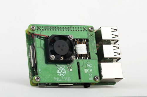
    One of the neat new features of the Raspberry Pi 3 Model B+ is its support for IEEE 802.3af Power-over-Ethernet (PoE). This standard allows up to 13W of power to be delivered over the twisted pairs in an Ethernet cable without interfering with the transmission of data. The Raspberry Pi board itself provides a PoE-capable Ethernet jack and circuit protection components; the power regulation electronics, which would be too costly and bulky to include on the main board, live on a separate HAT.

    Raspberry Pi PoE HAT Power over ethernet

    The Raspberry Pi 3B+ wearing a PoE HAT

    When we announced the 3B+, we revealed that an official Raspberry Pi PoE HAT was in the works and, after a few unforeseen production delays, we we released this HAT at the end of August. Feedback was, and remains, generally very positive; but fairly quickly, we started to see some reports from users who were experiencing issues.

    The problem

    The problem they reported was this: when powering certain Raspberry Pi units via the PoE HAT, it was not possible to draw the full rated current from the USB ports.

    Our 5V USB output, denoted VBUS, is fed by the main 5V rail via a current-limiting switch. This switch is designed to protect the system by detecting short-circuit, over-current, or reverse-voltage events, and disconnecting the USB ports in response. Our current-limiting switch is set to a limit of just over 1A.

    Despite the PoE HAT’s ability to supply up to 2.5A, the experiments we ran in response to the reports suggested that, when it was used to supply some boards, the USB supply would trip out at a much lower current. Mice and keyboards worked fine, but higher-current devices such as wireless dongles and hard disks would fail.

    Our initial theory was that the PoE HAT was injecting noise into the Pi via the 5V rail, and that this was somehow upsetting the switch. However, we were able to rule this out, since we found no evidence of high-frequency noise at the input to the switch. Another theory was that the flyback transformer’s close physical proximity to the switch was somehow coupling noise in. But we were able to rule this out as well: we showed that the behaviour persisted when the HAT was connected using a right-angle header, which moves the power electronics away from the Raspberry Pi.

    What was happening?

    The PoE HAT works by converting the incoming 48V from the Ethernet lines to 5V using a flyback transformer. In simple terms, the primary side of the transformer is switched across the 48V, and energy is stored in the transformer in the form of a magnetic field. The primary is then disconnected and the magnetic field collapses. This changing magnetic field induces a voltage (scaled based on the transformer turns ratio) in the secondary, which is rectified by a schottky diode and output capacitance. This output capacitance is formed from the output capacitors on the PoE HAT itself, the capacitors on the Raspberry Pi 5V rail, and, when the switch is on, the VBUS reservoir capacitors.

    The switching frequency of the flyback transformer is relatively low (~100 kHz). This means that when the system is under load, each switching cycle must transfer a relatively large amount of energy. During each cycle, the 5V rail is discharged according to the load on the system, and charged up again by the flyback’s secondary, dumping more energy into the caps. In each cycle, a spike of high current is pushed through the output diode into the capacitors.

    To cut a long story short, putting a current probe on the input to switch showed large current spikes, as energy from the flyback made its way into the VBUS reservoir capacitors. This was expected. However, it turned out that the switch was erroneously registering these spikes as true over-current events. The switch is supposed to have a filter that allows it to ignore brief spikes, but we discovered that only one of the two approved versions of the switch did this correctly.

    Current into switch (yellow) and VBUS voltage (blue)

    If it’s not been tested, it’s broken

    It’s a truism that if you don’t test an aspect of a design, it will certainly be broken. Those of us with a Broadcom background sometimes refer to this as Alan Morgan’s rule, after its most enthusiastic proponent.

    Extensive testing over all configurations, operating parameters, and use cases is the only way to minimise the likelihood of releasing a product with a hardware issue. Even relatively simple hardware can end up catching you out by throwing up some unexpected bug or issue. And even the big guys with huge development teams and test labs occasionally mess things up — anyone remember the Pentium FDIV bug?

    We made several mistakes with the first version of the PoE HAT:

    • USB load testing was performed using boards that had the working switch
    • Our field testing programme was abbreviated because the product was late
    • We didn’t inquire as to whether our field testers were using high-current peripherals (they weren’t)

    It’s embarrassing to have released a product with a bug like this, but it’s a lesson well-learned, and we will be improving our internal processes to prevent a recurrence.

    The solution

    Fortunately, this bug turned out to be easy to fix. We designed an L-C filter to apply further smoothing to the output current from the HAT. The filter consists of a little extra input and output capacitance and a 4.7µH inductor (chosen to have a suitable current rating and DC resistance), as well as 330mR resistor in parallel to provide damping. We were even able to wrap the mod up in a little mezzanine PCB that fits neatly underneath the board.

    The original, un-modded board

    Hand-modded board with L-C filter

    Final board with mezzanine

    Once we had confirmed that there was a problem with the PoE HAT, we took the product off sale, and recalled and reworked the outstanding units. We are now happy to announce that most Approved Resellers should now have the revised boards in stock. We believe that most people who have been affected by this issue have already returned their PoE HATs for a refund; if you’re experiencing issues and haven’t yet returned your product, you can get in touch with your reseller to arrange a replacement.

    I’d like to thank the members of the Raspberry Pi engineering team, our contract manufacturing partners Taijie, our licensee partners and Approved Resellers, and also the community members who kindly tested prototypes of the fixed board design. This hasn’t been the easiest product launch in our history, but hopefully the lessons learned have set us up well for the future.

    Website: LINK