Schlagwort: tech

  • This massive five-axis CNC machine is 3D-printable

    This massive five-axis CNC machine is 3D-printable

    Reading Time: 2 minutes

    Arduino TeamAugust 4th, 2021

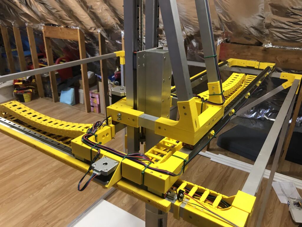
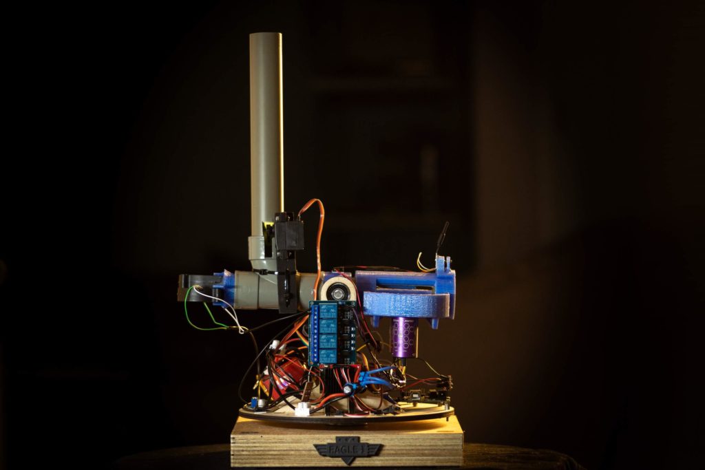
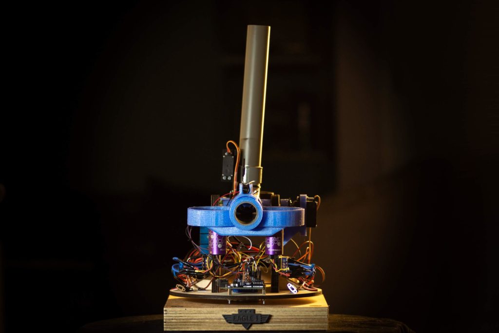
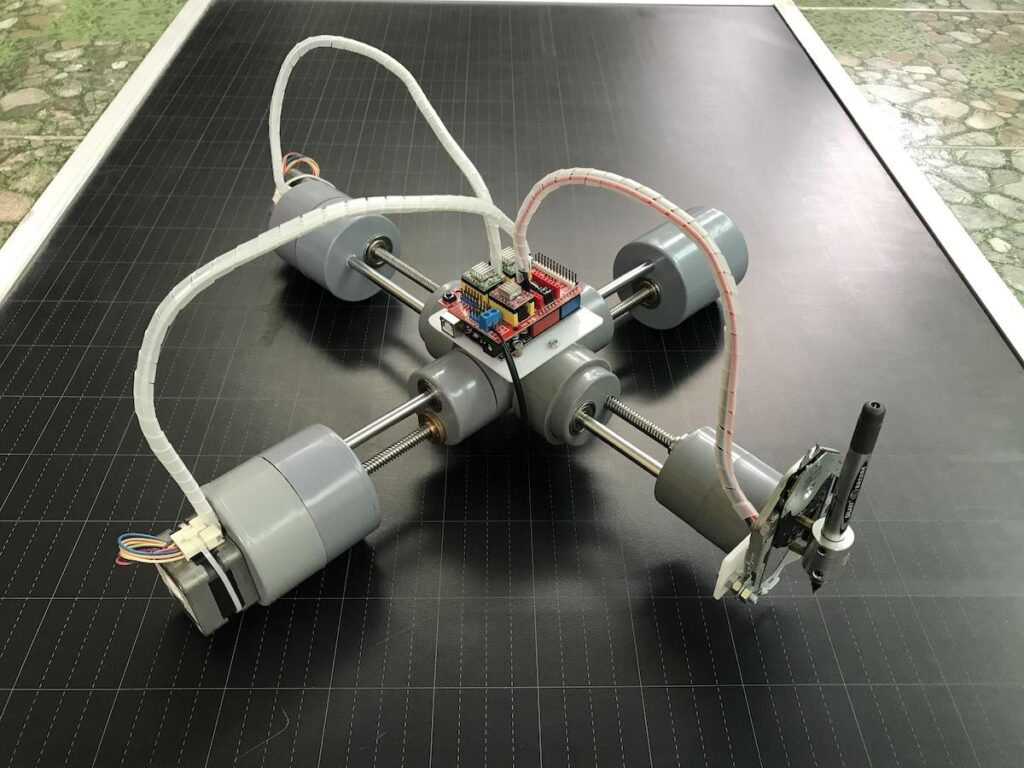
    CNC (Computer Numerical Control) mills, routers, and lathes are indispensable manufacturing tools. If you need a part that adheres to tight tolerances, you turn to a CNC machine. Industrial CNC equipment is usually large, heavy, and very expensive. But small models exist for light-duty hobby jobs. This DIY version designed by Brian Brocken stands out because it is huge, has five axes, and is 3D-printable.

    The most basic CNC mills and routers have three axes, so they move in the X, Y, and Z directions. But additional axes help a machine perform more complex operations. A fourth axis most often rotates the work piece, while a fifth axis tilts the spindle that rotates the end mill. It is rare to see a DIY CNC machine with five axes, but Brocken pulled it off with this project that has a massive work area of one square meter.

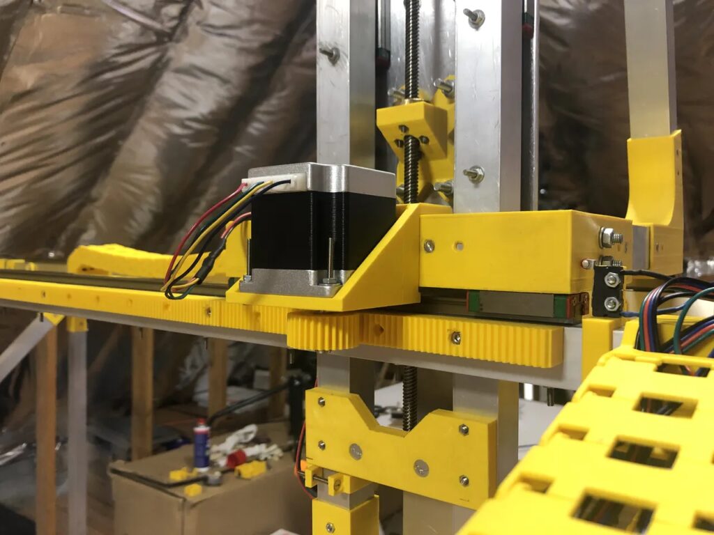
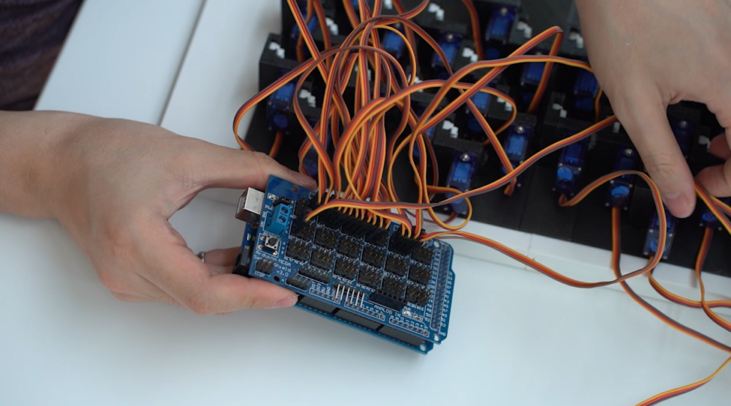
    Brocken performed all the design work within Autodesk Fusion 360. The frame of the machine is aluminum tubing and 3D-printed parts. An Arduino Mega controls the stepper motors through a RAMPS 1.4 board. It accepts standard G-code, so Brocken can create toolpaths in Fusion 360 or other CAM (Computer-Aided Manufacturing) software. The frame lacks rigidity and there is no way it could handle milling aluminum or even wood. But it can mill foam, which is the intended purpose. It can also perform 3D printing and laser cutting. Brocken isn’t quite finished building his CNC machine, but it is already semi-operational.

    [youtube https://www.youtube.com/watch?v=0mjJMsiF9To?feature=oembed&w=500&h=281]

    Website: LINK

  • Hacking an old Nintendo Zapper into a wireless remote

    Hacking an old Nintendo Zapper into a wireless remote

    Reading Time: 2 minutes

    Arduino TeamAugust 4th, 2021

    Those of us who have experienced the Nintendo Zapper while playing games such as Duck Hunt will probably have fond memories of it. However, with the rapid disappearance of CRT TVs and the aging of the physical mechanisms, YouTuber DuctTape Mechanic wanted to give an old Zapper a new lease on life. His modification integrated a small RF transmitting module into the top of the device, allowing it to be switched on by the trigger’s microswitch. With everything in place inside the Zapper, he moved onto the receiver.

    In order to get the incoming signals from the RF transmitter and turn them into an action, a receiver circuit was necessary. First, he soldered an RF module to a breadboard, along with an opto-coupling IC that isolates the sensitive electronics. From here, the receiver connects to an Arduino Uno that sets a pin high or low to turn the relay module + opto-coupler circuit on or off. In its current configuration, the Zapper acts like a toggle switch, where one press toggles everything to on while a subsequent press toggles everything off.

    As seen in the video below, being able to ‘zap’ your lights with the Nintendo Zapper looks really cool, and it will be interesting to see where DuctTape Mechanic takes it from here. 

    [youtube https://www.youtube.com/watch?v=-JHT3eCuiMQ?feature=oembed&w=500&h=281]

    Website: LINK

  • The Explore IoT Kit gets a mini-makeover

    The Explore IoT Kit gets a mini-makeover

    Reading Time: 2 minutes

    Arduino TeamAugust 3rd, 2021

    A year after the Arduino Education Explore IoT Kit launched globally, we’ve been improving the content of the kit and have made a few tweaks and upgrades!

    Since launch, we’ve been working with educators around the world on how we can make the kit even better (because everything can be better, right?) and the invaluable feedback they’ve given us has led to the following updates:

    – An introduction to the tools
    – Software IDE
    – Web editor
    – Libraries
    – IoT Cloud
    – Troubleshooting

    • Simpler sign-in functionality
    • Explanations of the benefits of teaching the Internet of Things to high school students right now

    We’ve also dived deeper into how the Explore IoT Kit can help students get career-ready, with new examples and illustrations that show how the kit helps develop the future skills the world will need, especially in the IT sector.

    Innovate, create, transform: Take your first steps in building internet-connected objects and explore the Internet of Things with Arduino Education.

    Website: LINK

  • A flask of goo that moves to the groove

    A flask of goo that moves to the groove

    Reading Time: < 1 minute

    Arduino TeamAugust 1st, 2021

    Ferrofluid is an interesting substance that is attracted to a magnetic field. While manually playing with a flask of such goo is interesting for a few minutes, GreatScott! had other ideas. His 3D-printed rig arranges a half-dozen custom electromagnets on the side of the flask. This allows an Arduino Nano to control the magnetic field arrangement, and thus fluid movement, with the help of six MOSFETs.

    To make things a bit more interesting, the build integrates an MSGEQ7 chip to analyze sound frequencies, which enables it to bounce the ferrofluid up and down as a three-zone VU meter. The setup also features a strip of addressable LEDs on the bottom for a lighting effect, creating a neat visual complement to your tunes!

    [youtube https://www.youtube.com/watch?v=l6dtyaNc0to?feature=oembed&w=500&h=281]

    Website: LINK

  • This magnetically levitated globe is an attractive piece of home decor

    This magnetically levitated globe is an attractive piece of home decor

    Reading Time: 2 minutes

    Arduino TeamAugust 1st, 2021

    While trying to think of his next project, Herwig Taveirne came up with the idea to craft some kind of levitating display that can showcase certain objects. Some of the criteria included completely magnetic levitation, stable floating, and overall safety since magnets can get quite hot when in use. 

    The floating globe case was constructed with a wooden lantern as its base, which helps everything look cleaner. The top of the lantern houses a large electromagnet that faces towards the bottom, along with a Hall-effect sensor that dangles below it to measure the distance between the globe and the magnet. An Arduino Nano is responsible for controlling the lifting magnet based on what the sensor reads in order to keep a stable position. There is also a set of six other coils at the base that get activated depending on the current rotation of the globe, and these provide small boosts to one side of the globe to keep it spinning smoothly. 

    Safety was a large concern for this project, and because of this, the primary lifting magnet is surrounded by a heatsink to dissipate excess thermal energy. A temperature sensor was attached too that can alert the Arduino if the device is getting too warm. Finally, a string of RGB LEDs lined the bottom of the lantern housing to give both ambient color and the current status of the system. 

    [youtube https://www.youtube.com/watch?v=BYnR8tr17ok?feature=oembed&w=500&h=281]

    Taveirne’s project was recently named a first prize winner in the Instructables Arduino Contest. To read more about this decorative piece, check out Taveirne’s write-up here.

    Website: LINK

  • Arduino-powered pinewood derby car scale measures center of gravity

    Arduino-powered pinewood derby car scale measures center of gravity

    Reading Time: 2 minutes

    Arduino TeamJuly 30th, 2021

    Constructing and racing a pinewood derby car is a great way to introduce young children to the world of engineering and mathematics. Many competitions will limit how heavy a car can be to avoid unfair advantages when it comes to momentum, meaning that contestants will try to add as much weight as possible. However, the center of gravity is also important since having it too far forward or backward can affect the acceleration or traction of the car. To address this problem, willemvl on Instructables created a small DIY scale that measures exactly where this center lands on the car to assist in balancing. 

    The main portion of the scale is the set of two load cells that measure the force being applied to their tops. They are connected to the Arduino Uno underneath via two digital IO pins. Data such as the front, rear, and total weight are displayed on a large 20×4 I2C LCD screen in the middle which is flanked by a set of buttons to calibrate the scale and begin measurements. 

    After going through the calibration process with a series of known weights and setting their calibration factors, the scale was ready to use. As can be seen in the project’s write-up, the center of gravity calculation is amazingly accurate, and it was used to help willemvl when he went to readjust the weights on the pinewood derby car.

    Website: LINK

  • Mr Innovative made an automated machine to cut four different colors of wires

    Mr Innovative made an automated machine to cut four different colors of wires

    Reading Time: 2 minutes

    Arduino TeamJuly 30th, 2021

    We all know as makers that trying to cut those little wires to the perfect length can be one of the most tedious and frustrating aspects of soldering together a project. Whether it is because the wire cutters slipped or the lengths of the conductors are all different, the lack of consistency is detrimental. This is why the maker and YouTuber known as Mr Innovative has created an automated multi-colored wire cutting machine that is able to achieve the precise wire length every single time.

    His device was constructed almost entirely from 3D printed parts, including the gears, mounts, and blade mechanism. Up to four spools of wire sit at the back on a long axle that lets them rotate while a gear and pulley pull the wire out. Rather than using a motor for each spool, a single DC motor with a gear on the end slides along a threaded rod and meets up with the gear on the spool. From here, the motor rotates and pulls the correct length of wire to the cutter. The cutting mechanism consists of an unmoving bottom piece with a blade facing upwards. Just above it is a second downward-facing blade that gets pushed down by a servo motor. A PCB was designed that connects the Arduino Nano, stepper motor drivers, screen, and power together while maintaining a small footprint.

    You can see how Mr. Innovative built this device below.

    [youtube https://www.youtube.com/watch?v=VW07FaIvl_c?feature=oembed&w=500&h=281]

    Website: LINK

  • Create projects fast, with no coding, using Oplà IoT Kit templates

    Create projects fast, with no coding, using Oplà IoT Kit templates

    Reading Time: 3 minutes

    Create projects fast, with no coding, using Oplà IoT Kit templates

    Arduino TeamJuly 30th, 2021

    Templates let you build IoT projects without code

    Templates are here for the Oplà IoT Kit. This is a new feature that takes you from unboxing your kit to uploading a sketch and getting a project up and running in record time. And you can do the whole thing without needing any coding.

    Arduino Cloud Templates for Oplà IoT Kit

    Arduino Cloud is all about ease and simplicity. So it’s been no small task in the background, creating a way to import dashboards, sketches, things and variables that get projects up and running in just a few clicks.

    To kick things off, we’ve brought these templates to the awesome Oplà IoT Kit. This way, you have more options than ever before. You don’t need any coding skills at all to make a fully functional, connected IoT project. It’s the spark that will start the fire of your new passion for electronics!

    Arduino templates for Opla IoT Kit

    Oplà IoT Kit Projects

    The kit includes a host of projects so you can get started with IoT. These projects are carefully developed to create a strong foundation that lets anyone develop a working understanding of connected projects. Whether you’re teaching or learning, this kit is for you.

    There’s still a lot of value in following these projects from start to finish, of course. Building control dashboards is one of the most powerful tools in the Arduino Cloud arsenal, for example. But there’s no quicker way to get started than importing a template. You can get to grips with things through pre-built, working demo content. Being able to see the finished project and work backwards is an excellent way to understand the inner workings.

    There’s a super simple wizard that helps you import an Oplà IoT Kit project. It walks you step-by-step through the short process, creating and uploading the sketch, connecting the devices and adding a dashboard. It’ll connect your boards to Arduino Cloud and set them up automatically as you go.

    Templates are ready and available for the following example Oplà IoT Kit projects:

    • Home Security Alarm
    • Inventory Control
    • Personal Weather Station
    • Remote Controlled Lights
    • Smart Garden
    • Thermostat Control
    • Thinking About You

    Simply register your kit, and get signed up to the Arduino Cloud. If you’ve got a new Oplà IoT Kit there’s a free 12 month subscription included in the box, although you can do all this with the free Cloud plan too. Once you’re in, select the project you want to build with your Oplà IoT Kit. Then just click the “Import” button and follow the wizard as it takes you through the quick and easy process.

    Do you like the new dashboard templates? Let us know if the comments where you’d like to see this Arduino Cloud feature go next.

    Website: LINK

  • Fire foam balls from this Arduino-based wireless Nerf sentry turret

    Fire foam balls from this Arduino-based wireless Nerf sentry turret

    Reading Time: 2 minutes

    Arduino TeamJuly 28th, 2021

    Named the grand prize winner of Instructables’ Arduino Contest, a maker known as otjones99 has created an interesting take on the classic Nerf sentry turret design by building one that uses an FPV headset to see and fire at targets. The turret consists of a turntable for moving the assembly side-to-side, along with a simple servo mechanism for tilting the end up and down. Small foam balls are ejected from the turret by a pair of counter-rotating wheels that were taken from a couple of blower style fans.

    In order to control the rotating base and the loading/tilting mechanisms, a single Arduino Uno was positioned at the bottom and connected to the two servos and the ESCs for the spinning wheels. Commands for actuating the sentry are received by the onboard nRF24L01 wireless module that sends them to the Uno over the SPI bus. 

    The user is able to move the sentry turret by turning a pair of potentiometers within a Logitech joystick attached to an Arduino Nano. There is also a set of momentary pushbuttons to switch the safety on or off and to launch. This data gets transmitted from the nRF24L01 module onboard to the other one on the turret. 

    This project is a really fun way to explore both first-person control and topics in wireless communication. To read more about the sentry turret, you can check out otjones99’s well-documented tutorial here.

    [youtube https://www.youtube.com/watch?v=lVpgIXSY_CA?feature=oembed&w=500&h=281]

    Website: LINK

  • Pomodor-glow! Improve your study session with this colorful countdown timer

    Pomodor-glow! Improve your study session with this colorful countdown timer

    Reading Time: 2 minutes

    Arduino TeamJuly 28th, 2021

    Studying without getting distracted can pose a significant challenge to students, which is why having small productivity hacks could be beneficial. Alexandra Charland — who goes by alch_emist on Instructables — wanted to try out the popular Pomodoro technique, which involves working for 25 minutes uninterrupted and then taking a break for five minutes after. To make this approach a bit more appealing, Charland created a countdown box that can light up in different colors.

    Charland’s device is comprised of an Arduino Nano 33 IoT that runs a timer for the 25- and five-minute intervals. On the front of the enclosure is a pair of seven-segment displays that show the time remaining on the main timer, and even though these require 10 pins, a shift register can easily be added in the future. The side of the box has a large red arcade pushbutton that when pressed starts or stops the timer. 

    The timer is not the only thing that’s cool about the study box. The entire thing has a string of NeoPixels in the bottom that change color when the slider is moved. There’s also a buzzer that begins to sound when the timer expires to notify the user when it is time for a break.

    If you want to build your own for the fall semester, check out Charland’s write-up here.

    Website: LINK

  • The P-CNC Plotter is a DIY drawing machine ‘disguised as a quadruped robot’

    The P-CNC Plotter is a DIY drawing machine ‘disguised as a quadruped robot’

    Reading Time: 2 minutes

    The P-CNC Plotter is a DIY drawing machine ‘disguised as a quadruped robot’

    Arduino TeamJuly 27th, 2021

    In their quest to create a portable CNC plotter, Instructables user tuenhidiy combined several PVC pieces with a couple of motors to build the P-CNC Plotter. The small machine — which was designed to resemble a quadruped robot — features an Arduino Uno and a Gbrl control shield at its heart that takes incoming G-code and translates it into motor movements. The X axis consists of a single NEMA-17 stepper motor that actuates a threaded rod to slide the rest of the device along a path. 

    There is a central PVC assembly that holds both the threaded and smooth rods for both the X and Y axes while letting the entire thing move. Tuenhidiy was able to repurpose the linear gliding mechanism from a CD player as the Z axis, thus letting the pen or other drawing utensil go up and down with great precision. A set of three A4988 stepper motor driver modules provide the current to both the NEMA 17 motors and CD drive components. 

    Images are drawn within the vector-based program Inkscape, and they normally include text, basic shapes, and splines that the toolhead can follow. G-code was exported from Inkscape by using an extension, and this could then be sent to the Gbrl-enabled Arduino. To read more about this project, you can check out tuenhidiy’s write-up here.

    [youtube https://www.youtube.com/watch?v=P1GsmJz2r8U?feature=oembed&w=500&h=281]

    Website: LINK

  • Present! uses an Arduino and a PIR sensor to keep you from embarrassing yourself on Zoom calls

    Present! uses an Arduino and a PIR sensor to keep you from embarrassing yourself on Zoom calls

    Reading Time: 2 minutes

    Arduino TeamJuly 27th, 2021

    Teleconferencing is more popular than ever, especially with the ongoing COVID-19 pandemic, but we have also seen an increase in embarrassing videos from people who were unaware that their cameras were still on. To address this problem, Charitha Jayaweera came up with a clever solution that he calls the “Present!” — a system that uses an Arduino Nano and HC-SR501 passive infrared sensor to detect if there is a person in front of the computer and automatically disable their camera and microphone if not.

    The device’s enclosure was designed to be easily 3D-printed and mounted to the top of a monitor or laptop screen. The handy clip on the bottom can be bent and fitted to an edge where it can also tilt. A series of screws hold the bottom plate onto the top piece. 

    Jayaweera wrote a great program for taking information from the serial port that the Nano is attached to and controlling the Zoom app with it. The Python script begins by initializing the serial port within a second thread to keep the GUI running smoothly. Next, a tkinter window is created with two radio buttons for selecting if the camera is currently on or off. And finally, the window has a small bit of text that shows the current state of both the Arduino and the camera on Zoom.

    You can see a demo video of Present! below and view its write-up here.

    [youtube https://www.youtube.com/watch?v=eGks0JywzLk?feature=oembed&w=500&h=281]

    Website: LINK

  • Scan items from the real world into your Arduboy games with the Ardumiibo

    Scan items from the real world into your Arduboy games with the Ardumiibo

    Reading Time: 2 minutes

    Arduino TeamJuly 27th, 2021

    Inspired by a recent project involving Disney’s MagicBand technology, William Wimberly and Anthony Pallitta created an Arduboy-compatible RFID scanner they call the Ardumiibo, along with a DIY rumble pack. The Ardumiibo got its name from Nintendo’s Amiibo platform, which allows players to tap NFC-equipped figurines and see them within a game. In a similar manner, the Ardumiibo enables users to scan their NFC tags on a device built from an Arduino Leonardo board and PN532 RFID module. 

    The scanning system is contained within a small 3D-printed enclosure that also has a NeoPixel ring around the top for some added flair. It connects to a Tiger Electronics handheld-style host Arduboy device via a serial cable, which allows for programs on the gaming system to simply implement the protocol for communicating with the Ardumiibo. As for the rumble pack that is integrated into the scanner, it is attached to the Arduboy over pin 2 that lets the game send pulses with the Tone commands for haptic feedback or playing small songs. 

    The Ardumiibo is a great little gadget that lets Arduboy game designers easily add both rumble and NFC capabilities to their consoles. You can read more about the duo’s work in their Hackster write-up here and find their design files and code here on GitHub.

    [youtube https://www.youtube.com/watch?v=hHm78brrl0U?feature=oembed&w=500&h=281]

    Website: LINK

  • Send text messages over ham radio with the HamMessenger

    Send text messages over ham radio with the HamMessenger

    Reading Time: 2 minutes

    Arduino TeamJuly 27th, 2021

    Ham radio, or amateur radio, is a hobby enjoyed by millions of enthusiasts around the world. The FCC in the US and similar organizations in other countries provide amateur radio licenses that allow hobbyists to communicate on designated radio bands. Most ham radio operators communicate by voice, but ham radios can transmit other kinds of data. Dale Thomas built HamMessenger, which is a portable device that enables users to send text messages through their ham radios.

    If you remember the early days of the internet, you have heard for yourself that audio can carry digital data. Dial-up internet uses a modem to transmit that audio through standard phone lines. HamMessenger uses a similar methodology to encode a text message as audio. If someone listening on that frequency also has a HamMessenger device, they can decode the text message. Messages are not encrypted, so you shouldn’t use HamMessenger for sensitive information. But it’s a fun way to chat with your ham radio buddies.

    HamMessenger contains two Arduino development boards. An Arduino Mega handles most of the functionality and a separate Pro Mini acts as a MicroAPRS modem. A Neo-6M GPS radio module lets you send position information along with your text messages. The HamMessenger’s custom PCB has a small 0.96″ OLED screen to display the messages. You input text via an M5Stack CardKB keyboard. Power comes from a pair of 18650 lithium-ion battery cells. The output from the HamMessenger is an audio signal, which feeds into any ham radio — even a handheld model. Thomas plans to design an enclosure soon, but you can follow his instructions to put the rest of the hardware together right now.

    Website: LINK

  • Meet your new table tennis coach, a tinyML-powered paddle!

    Meet your new table tennis coach, a tinyML-powered paddle!

    Reading Time: 2 minutes

    Arduino TeamJuly 23rd, 2021

    Shortly after the COVID-19 pandemic began, Samuel Alexander and his housemates purchased a ping pong set and began to play — a lot. Becoming quite good at the game, Alexander realized that his style was not consistent with how more professional table tennis players hit the ball, as he simply taught himself without a coach. Because of this, he was inspired to create a smart paddle that uses an integrated IMU to intelligently classify which moves he makes and correct his form to improve it over time. 

    Alexander went with the Nano 33 BLE Sense board due to its ease of use and tight integration with TensorFlow Lite Micro, not to mention the onboard 6DOF accelerometer/ gyroscope module. He began by designing a small cap that fits over the bottom of a paddle’s handle and contains all the electronics and battery circuitry. With the hardware completed, it was time to get started with the software.

    The Tiny Motion Trainer by Google Creative Lab was employed to quickly capture data from the Arduino over Bluetooth and store the samples for each motion. Once all of the movements had been gathered, Alexander trained the model for around 90 epochs and was able to achieve an impressive level of accuracy. His build log and demonstration video below shows how this smart paddle can be used to intelligently classify and coach a novice player into using better form while playing, and it will be fun to see just how good the model can get. 

    [youtube https://www.youtube.com/watch?v=j8hQ66LXutc?feature=oembed&w=500&h=281]

    Website: LINK

  • This Arduino-powered robotic fish swims like the real thing

    This Arduino-powered robotic fish swims like the real thing

    Reading Time: 2 minutes

    Arduino TeamJuly 23rd, 2021

    Biomimicry is often used to take the designs that nature has perfected over a period of millions of years and incorporate them into our own technology. One maker who goes by mcp on YouTube took this idea one step further and created a fish that can swim in the water like the actual creature. By carefully analyzing and studying the patterns a fish makes while it scurries through a lake, he was able to reduce these motions down to just a few joints. 

    The body of this DIY robotic fish was constructed from a series of four joints that each contain a single mini servo motor to control their movements. Next, an Arduino Nano was selected as the microcontroller board due to its small size and ample amounts of GPIO pins. In order for the fish to sense if there is an obstacle in the way and avoid it, the device also features “eyes” that utilize IR emitter/receiver pairs.

    Once the spine of servo motors was combined with the Arduino and a set of LiPo batteries, mcp slipped over a skin made from a waterproof latex-like material that aids in moving throughout the water. In his video below, the DIY robotic fish can be seen oscillating freely through a bathtub full of water, along with a pool. His device works very well as it generates plenty of forward force to swim wherever it wants while avoiding obstacles. 

    [youtube https://www.youtube.com/watch?v=gemf0floD98?feature=oembed&w=500&h=281]

    Website: LINK

  • Using the MKR IoT Carrier board as a game console

    Using the MKR IoT Carrier board as a game console

    Reading Time: 2 minutes

    Arduino TeamJuly 21st, 2021

    One of the first things many makers try to do when they receive a new piece of cool hardware is write a game for it. This is exactly what Johan Halmén did with his Breakout console that uses the Arduino MKR IoT Carrier board and an MKR1000 to both run and display the game. 

    Breakout typically involves moving a paddle horizontally along the bottom of the screen to bounce a ball that can destroy the bricks above it. However, since the carrier board’s color OLED screen is circular, Halmén had to create a different version of this, which he calls “BreakIn.” His game features a bunch of hexagonal tiles in the middle and a paddle that moves around the outside that is controlled by the onboard accelerometer. This lets the player tilt the device to move their paddle quickly and accurately. 

    Getting the circular display to work was a bit more of a challenge than a normal square one because coordinates had to be mapped using a bit of trigonometry first. Additionally, figuring out the angle of tilt and the collision geometry took some math as well. But once everything was up and working, the game was very fun to play, as can be seen in Halmén’s demo video below. 

    [youtube https://www.youtube.com/watch?v=_t40IsB9nrk?feature=oembed&w=500&h=281]

    To read more about the code that went into this project, check out its Instructables write-up here.

    Website: LINK

  • The Snoring Guardian listens while you sleep and vibrates when you start to snore

    The Snoring Guardian listens while you sleep and vibrates when you start to snore

    Reading Time: 2 minutes

    Arduino TeamJuly 20th, 2021

    Snoring is an annoying problem that affects nearly half of all adults and can cause others to lose sleep. Additionally, the ailment can be a symptom of a more serious underlying condition, so being able to know exactly when it occurs could be lifesaving. To help solve this issue, Naveen built the Snoring Guardian — a device that can automatically detect when someone is snoring and begin to vibrate as an alert. 

    The Snoring Guardian features a Nano 33 BLE Sense to capture sound from its onboard microphone and determine if it constitutes a snore. He employed Edge Impulse along with the AudioSet dataset that contains hundreds or even thousands of labeled sound samples that can be used to train a TensorFlow Lite Micro model. The dataset within Edge Impulse was split between snoring and noise, with the latter label for filtering out external noise that is not a snore. With the spectrograms created and the model trained, Naveen deployed it to his Nano 33 BLE Sense as an Arduino library.

    The program for the Snoring Guardian gathers new microphone data and passes it to the model for inference. If the resulting label is “snoring,” a small vibration motor is activated that can alert the wearer. As an added bonus, the entire thing runs off rechargeable LiPo batteries, making this an ultra-portable device. You can see a real-time demonstration below as well as read more about this project on Hackster.io.

    [youtube https://www.youtube.com/watch?v=z2hAgEOMowM?feature=oembed&w=500&h=281]

    Website: LINK

  • An Arduino-powered micro quadruped that fits in the palm of your hand

    An Arduino-powered micro quadruped that fits in the palm of your hand

    Reading Time: 2 minutes

    Arduino TeamJuly 20th, 2021

    Arduino-powered quadruped robots are quite common projects for hobbyists to build once they are a bit more comfortable with embedded systems. One problem with many of the pre-designed quadruped platforms is that they require a lot of time to assemble owing to their large size. This is what inspired Technovation to come up with their own micro quadruped robot, which requires only a fraction of the normal amount of material and hours to construct.

    The robot is based around a central chassis that houses the Arduino Uno and sensor shield components, which provide power and signaling to the motors. Underneath this hardware stack are four servos that can rotate to the side and act as hip joints. Lastly, each leg is comprised of two servos to allow for forward motion. 

    In order for the Arduino to translate a desired direction into discrete positions for the servo motors, Technovation had to implement a few kinematic equations within the robot’s firmware. These consist of movement functions, which create gaits by specifying where and when each leg should move. Several parameters, including speed, leg length, and even the motion paths themselves, have the ability to be fine-tuned or expanded to add more capabilities.

    You can see how this micro quadruped works in its demonstration video here or you can read more about the project in Technovation’s Instructables write-up.

    [youtube https://www.youtube.com/watch?v=Gz9LlvCPZIA?feature=oembed&w=500&h=281]

    Website: LINK

  • Kinetic digital clock takes 7-segment displays to another dimension

    Kinetic digital clock takes 7-segment displays to another dimension

    Reading Time: 2 minutes

    Arduino TeamJuly 20th, 2021

    Seven-segment displays have been around for ages, and they have a really cool retro aesthetic about them. Over on Instructables, user alstroemeria (known as Jacky Mok in real life) decided to build a different kind of display that utilizes individual servo motors to slide the segments out, thus creating a 3D clock. The main board in this project was the Arduino Mega, which was selected due to its large number of digital GPIO pins that can set all 28 of the servos to the correct positions. 

    The current time was tracked using the DS3231 RTC module that stores the time and can keep it even if power is removed. The program Mok wrote first initializes the servos and sets them in the “off” position. Within the main loop, the time is retrieved from the RTC module and converted into digits. From here each digit is mapped to a series of segments which are then moved into the correct spot with the corresponding motor. 

    The clock enclosure Mok designed is quite elegant and captures the feeling of a classic seven-segment display. As seen in the accompanying video, watching the digits slowly move and morph into various shapes can be mesmerizing. More details on the concept and its construction can be found on Instructables

    [youtube https://www.youtube.com/watch?v=lkjKl4GjinQ?feature=oembed&w=500&h=281]

    Website: LINK

  • This interactive beer pong table is lit, literally

    This interactive beer pong table is lit, literally

    Reading Time: 2 minutes

    Arduino TeamJuly 20th, 2021

    Beer pong and its derivatives are some of the most enjoyed games on college campuses, but they are not all that exciting with just a few cups at either end of a plastic folding table. Meet the Interactive Pong Table, which was created by Instructables user boregan1. It features a fully-custom tabletop gaming experience with a large LED matrix running underneath the center and 20 total cup zones that can be used to play more intriguing games. There are even arcade buttons surrounding the sides of the table that act as video game controllers when the players just want a quick game. 

    A total of four Arduino Nanos were used to build the Interactive Pong Table, with each one being responsible for a single aspect and communicating with the others via the I2C protocol. At the heart is the main controller which handles the central RGB LED matrix and the game logic. It can display fun, animated graphics in the middle of the table and even run classic pong. The cups at either end of the table are tracked with the use of infrared emitter/receiver pairs that change their voltage whenever a cup is removed. This allows the LEDs underneath the cups to light up or play an animation if one is removed. Additionally, the game running on the main controller can keep score of which player has fewer cups remaining.

    The Interactive Pong Table is a well-built project that showcases how creative one can be with just a few boards and some RGB LEDs. You can read more about it here on Instructables or see a demo below!

    [youtube https://www.youtube.com/watch?v=lq4ufvAfOYU?feature=oembed&w=500&h=375]

    Website: LINK

  • This light painting machine puts a new spin on the old geometric chuck

    This light painting machine puts a new spin on the old geometric chuck

    Reading Time: 2 minutes

    Arduino TeamJuly 19th, 2021

    Light painting is a fun way to create digital images by using just a few points of light to “draw” across a camera with a long exposure time. This gives the illusion of a virtual streamer being dragged on the canvas and can produce amazing photos. Ted Kinsman wanted to build a light painting machine, which mimics the geometric chucks from the 1860s that used several spinning platters on a lathe that rotated at different speeds to carve ornate patterns into wood. His version has a series of three platters all stacked on top of each other and are driven by three stepper motors. 

    A single Arduino Uno runs the program for the geometric light painting machine, and it is responsible for controlling the stepper motors through its three attached TB6660 motor driver modules. The code works by first initializing each stepper as an AccelStepper object and then setting its max speed. The magic comes from this next part, and each motor gets assigned a constant speed value that determines what kind of pattern will be drawn. And finally, the motors are run at these speeds until the machine is stopped. The vast number of combinations from these variables means that even a small change to the motors’ speeds or where the LED is positioned on the top platter can generate wildly different results.

    You can read more about Kinsman’s geometric light painting machine in his article on PetaPixel.

    Website: LINK