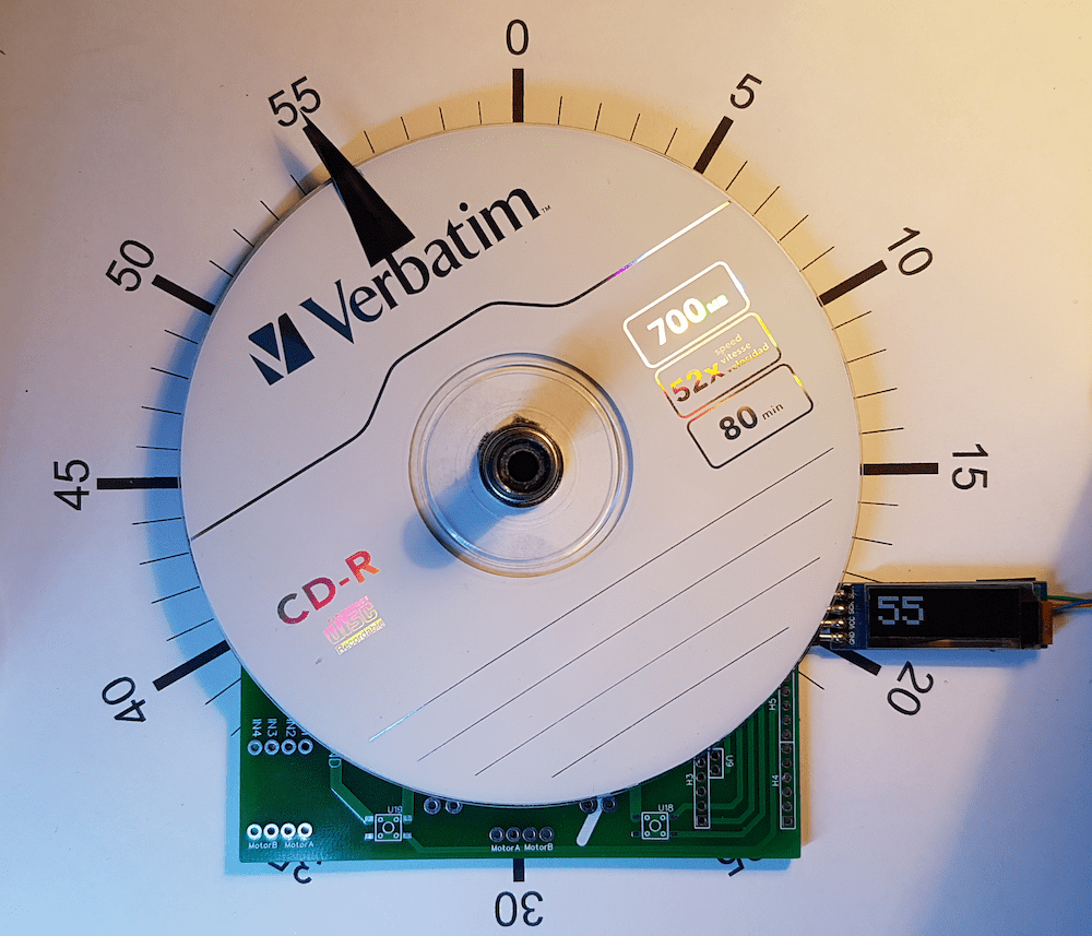
Being able to derive the absolute position of an object is vital in countless applications, primarily for anything that uses a motor. Instructables user holybaf had the idea to build their own rotary encoder, which has 60 degrees of resolution and utilizes a CD to act as a precise clock.
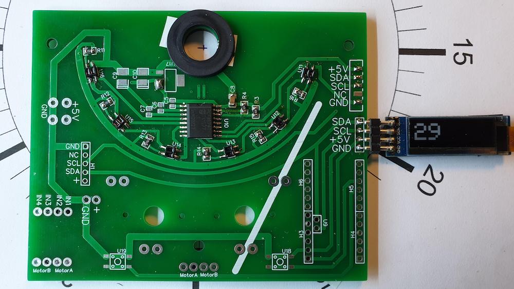
To accomplish this, they first laid down a single circular track featuring patterns of light and dark areas that each correspond to a single value. By reading these areas with a set of six infrared emitters/detectors and comparing their current reading to the previous one, an absolute position can be determined.
A custom PCB was also designed for this project, which contains the aforementioned IR detectors along with a PCF8574 I/O expander and a pair of headers for connecting an Arduino Uno and an OLED screen for viewing relevant information such as the current time. After attaching a motor and loading some code, the clock was finally complete.
You can see this device in action below or you can check out the build log in more detail here on Instructables.
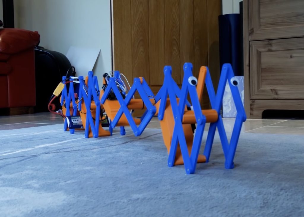
Self-propelling robots come in a whole host of shapes, sizes, and capabilities, with some being able to fly while other can walk on just a couple or many legs. But YouTuber James Bruton wanted to innovate on this concept even further by designing and building a robot that mimics an earthworm through extending and contracting segments at certain times to slowly inch along the ground. This class of motion is called peristalsis, and it works by constricting a ring of muscles to propagate material, such as in the case of the digestive tract, or to move an entire body.
For Bruton’s first prototype, he went with four identical segments that each contain a single linear actuator which pushes or pulls within a scissor mechanism to move the segment. The actuators were then connected to an Arduino Uno that is responsible for sending pulses that dictate the extent of motion in a series. Although it worked at least somewhat, this initial design proved far too slow, thus leading to a redesign.
In this next iteration, each segment houses a powerful servo motor at the end of a scissor mechanism that rotates to extend or contract the segment. This way, the worm can raise up, fall further away, and pull the rest of the body along, akin to an inchworm.
For more details on the project, you can watch Bruton’s video or check out his GitHub repository here.
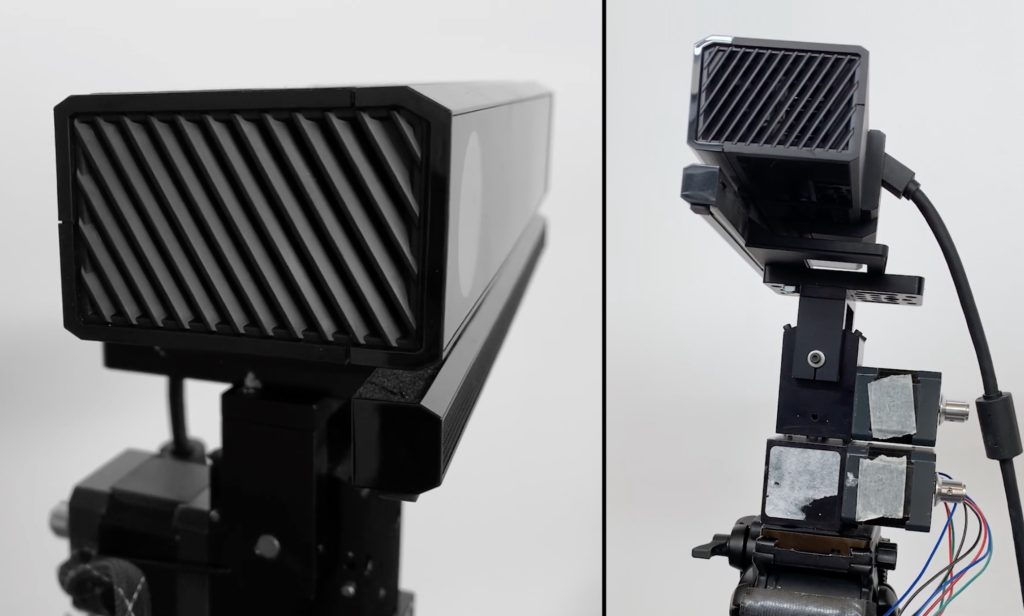
Capacitive touchscreens today use a digitizer to pinpoint the coordinates of a finger tap. That makes sense for smartphones and tablets, but isn’t ideal for large scale applications. If you want to recognize touches on the scale of an entire wall, a Kinect sensor could be more appropriate. But such a setup traditionally has a limited range — usually less than 1.5 meters. FarOut is a new system developed by Carnegie Mellon researchers that extends Kinect touch sensing range to 3 meters.
Like other Kinect-based touch sensing systems, this can detect the coordinates of a finger tap on an ordinary wall. Due to resolution and other factors, a typical Kinect sensor can’t reliably detect the position of a fingertip during a tap at a long distance. But the FarOut team doubled that distance using a series of techniques, including thermal mitigation, background subtraction, and de-noising. To reduce noise and increase the Kinect’s effective resolution, they turned to Arduino.
The Kinect v2 sensor is stationary, which limits the resolution of the depth map that it creates. By moving the camera a tiny amount, the team increased the sensor’s effective depth resolution by a substantial degree. It’s similar how you move your head to better judge the distance to a faraway object. They introduced that movement using a custom pan-tilt mount for the Kinect sensor. That mount has two stepper motors that an Arduino Uno controls via a CNC shield. With sophisticated post-processing, FarOut can detect a touch 3 meters away with a precision of less than 10 millimeters.
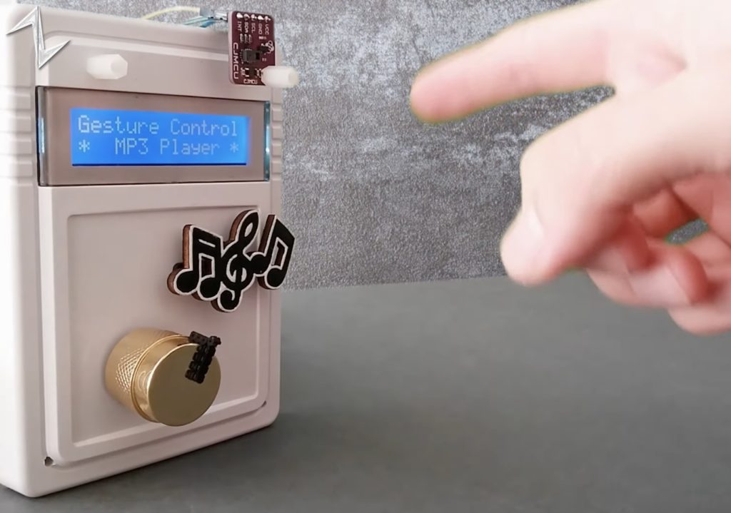
The classic MP3 player was a truly innovative device for its time, however with the advent of modern smartphones and other do-it-all gadgets, they have largely fallen by the wayside. In order to add a new twist, Norbert Zare decided to implement an MP3 player that not only responds to user inputs by moving the volume knob and tilting some notes to signal the next track, but can also be controlled simply by waving a finger in front of it.
Gesture control was achieved using the PAJ7620U2 sensor, which can quickly detect movements within a 3D space and output its findings over the I2C bus to a host microcontroller. Zare set up his Arduino Uno’s program to continually check for a new gesture, and based on the one being read, perform a certain action. For example, making a clockwise circle with a single finger will increase the volume, turn the servo attached to the volume knob, and change the text on the attached LCD to match. Other functions include skipping tracks and resuming/pausing.
When a motion has been picked up by the Uno, it also sends a signal to an attached and partially disassembled MP3 player’s button pad that controls the actual music being played as well as its volume. You can read more about this project here on Hackaday.io and check out Zare’s video below.
You’ve now got a way to optimize your Arduino Cloud dashboards for small screens, and Facebook login for the smartphone apps and your account. It’s been a busy few weeks! Only yesterday we rolled out LoRaWAN connectivity in Arduino Cloud using The Things Stack. Now we’ve even more great features to tell you about, so let’s jump right into them.
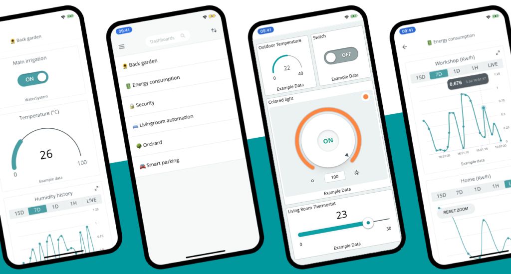
Mobile Optimized Dashboards for Arduino Cloud
Dashboards are one of Arduino Cloud’s crowning achievements. Fully customizable, and a powerful way to control boards, devices and projects, while also letting you visualize all kinds of data. It really is a cornerstone of Arduino Cloud’s offering.
A little while ago we made some changes to widget sizes, and the way they’re labelled. It gave you a much better view of the data, and made the sizing more compact. This was the first step in a redesign of Arduino Cloud dashboards that now let us improve visibility on small screens, too.
As you probably know, your dashboards instantly work in the free Arduino IoT Remote app, too. It gives you smartphone control with no coding required. Today this great feature gets a shot in the arm, as you can now edit a dashboard’s layout for a mobile screen.
Let’s say you add a button to a new dashboard. You can now increase its size on the big screen, but reduce its size on the mobile layout. They can be in totally different positions, too. Arduino Cloud will automatically display the dashboard in the optimal size depending on your device. So you always get the best view and most ergonomic layout.
Any settings for the widgets are maintained regardless of the dashboard size. So if you link the button to a variable on the desktop dashboard, it’s also linked for the mobile layout. This way, you can optimize the layout without having to replicate any work in the settings.
At the top of the dashboard screen, you’ll now see a mobile layout button. This lets you switch between views, so you can customize the dashboard for both screen sizes. It’s available right now, so go give it a try.
Facebook Login for Arduino Cloud
Since we’re talking about Arduino Cloud updates for small screens, we also added another minor, but very useful tweak.
You can already log into your Arduino Cloud account using Google or Apple accounts. Or your Arduino account, obviously. There’s now the option to log in by connecting to Facebook, too.
It speeds up the process by only requiring a quick button click/tap, so you can get on with building those awesome mobile dashboards even faster!
As always, we want to hear your thoughts on these changes, so please let us know over on social media.
The Things Stack (TTS) and Arduino Cloud are now fully interfaced and open up a world of connected opportunities. When you configure a LoRaWAN device now, it’ll automatically be registered on The Things Stack platform, too.
An abbreviation of long range wide area network, LoRaWAN is a very low power wireless connectivity system, much like Wi-Fi. But it operates on a different (unlicensed) frequency that’s able to transmit and receive signals a lot further. It boasts distances that are measured in kilometers, rather than meters, as with WiFi or Bluetooth.
LoRa isn’t new to Arduino, of course. But now your devices can make use of over 22,000 public gateways around the world that are connected to the TTS service. In a very over-simplified way, these gateways translate radio packets into internet packets. A radio signal effectively becomes data sent over the internet, and vice versa. This vastly extends wireless internet coverage and connects remote IoT devices to your Arduino Cloud.
It’s not just about putting sensors, devices or projects in remote or rural locations, though. It’s about connecting to the internet where there is no Wi-Fi, and without the need for a costly cellular data connection. And it’s power consumption is very low. So a lot of these far distant devices can run on batteries or solar power.
Things, Things and More Things
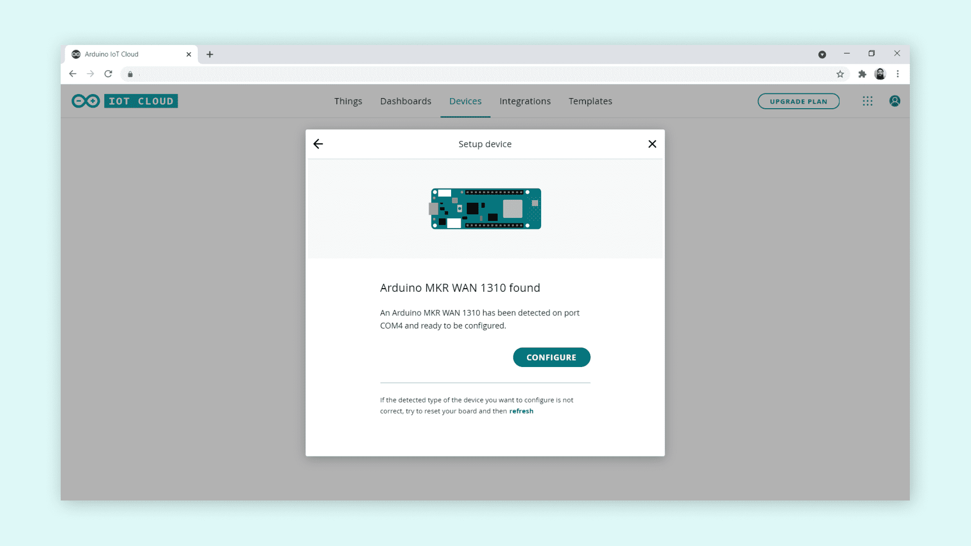
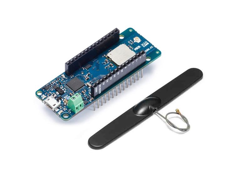
When you configure a new LoRaWAN compatible device in your Arduino Cloud, such as a MKR WAN 1300, it’s now automatically registered as a device on The Things Stack.
You’ll automatically see a new menu during setup, which lets you select your region. This is important, as different regions and countries use different LoRaWAN frequency bands.
And that’s it! No need for you to do anything else. Easily the simplest and fastest way to connect to LoRa devices in an Arduino project. Or any electronics project, for that matter, since Arduino Cloud lets you seamlessly connect all kinds of different devices.
Complete the setup just as you would with any other device on Arduino Cloud. Sync your variables, connect your devices, build your dashboards. As long as your board is in range of a TTS-connected gateway, it’s part of your Arduino Cloud. Just as if it was sitting next to you on your Wi-Fi network, even though it might be 15 kilometers away! Or you could set up your very own LoRaWAN gateway that supports TTS, if you don’t have one in range.
There’s a more detailed tutorial over on Arduino Docs, although it’s not a complex procedure by any means. It’s got some excellent advice on setting up and accessing The Things Console, which LoRa fans will find very useful. Then there’s a quick and easy test project to make sure everything’s working as you want it to.
It’s still early days for LoRa. But any Arduino lover who takes an interest in this exciting technology will quickly get hooked on it, and the possibilities it offers. Tell us all about your LoRa projects over on social media, and how you’re building them on Arduino Cloud.
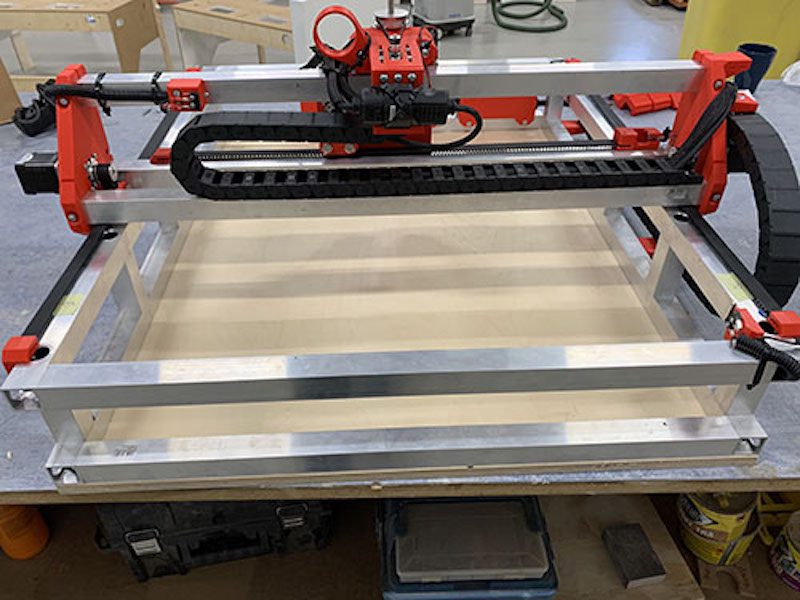
3D printers are very popular in the maker community and CNC machines complement them well. While 3D printers fabricate parts by adding material over time, CNC mills and routers fabricate parts by subtracting material. That is preferable when working with large parts or when you require a lot of precision. If you want an affordable option, this guide will show how to build Ivan Miranda’s 3D-printed CNC machine design.
Miranda posted his first video about this 3D-printed CNC machine back in March, 2020. He eventually published the design files on his website, but didn’t provide many details on parts sourcing or assembly. The GitHub page linked above, created by Max Fischer, provides thorough guidance for people looking to build their own machines based on Miranda’s design. It gives you a detailed bill of materials and walks you through the entire build process with step-by-step photo instructions.
While this machine does require a lot of square tube aluminum extrusion and hardware like linear rails and bearings, all of the custom mechanical parts are 3D-printable. For strength and mechanical stability, you’ll want to print those using a material like PETG. The controller board is an Arduino Uno combined with a CNC shield, which controls the stepper motors via drivers. Like a 3D printer, the X and Y axes utilize drive belts and the Z axis has a leadscrew. The spindle motor, which spins the cutting end mill, is a handheld electric router.
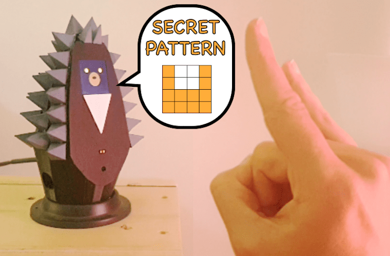
Detecting shapes and gestures has traditionally been performed by camera systems due to their large arrays of pixels. However, Jean Peradel has come up with a method that uses cheap time-of-flight (ToF) sensors to sense both objects and movement over time. Better yet, his entire project is housed within a 3D-printed “Grumpy Hedgehog” that contains not only the sensors, but a highly-interactive 1.44” LCD screen as well.
Peradel’s smart home companion is capable of picking up several different kinds of movements and patterns to perform a wide variety of actions such as sending keystrokes to a PC, controlling a light, or actuating a servo motor. This is accomplished by taking VL53L1X ToF modules, which have a 16×16 scanning array and communicate over the I2C bus. Once the attached Arduino MKR WiFi 1010 has read this data, it can determine if the object (which appears closer on the grid) has moved up, down, left, or right.
In order to make this project a bit more friendly, Peradel designed a small enclosure/stand that houses the VL53L1X near the base. Near the top is a small LCD which shows animated hedgehog faces, the “sensor’s view” of the object, and the associated action being taken.
You can read more about the Grumpy Hedgehog gesture sensor here on Hackaday.io.
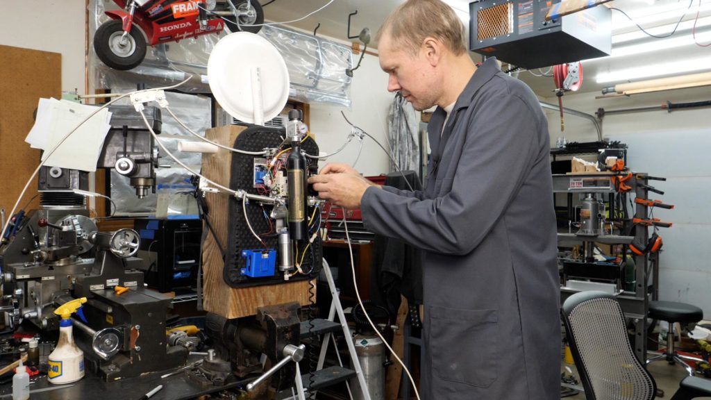
This year for Halloween, Quint BUILDs wanted to make something special for his daughter’s costume. Quint’s idea was to design and fabricate a pair of mechatronic dragon wings that can mount to a user’s back and move in three different modes by utilizing a set of pneumatic air cylinders.
The prototype began as a single air cylinder connected to a relay that was, in turn, controlled by a single Arduino Micro and button. This way, Quint could finely tune the timings and pressures required for the device. After 3D printing a simple controller, machining a few aluminum plates, and welding it all together into a second prototype, it was time to experiment with programming more complex movements.
Three pneumatic cylinders were used to create a couple axes of motion. First, the larger base cylinder moves a central piston vertically, thus extending and retracting them outwards. Each wing can flap independently through the use of two smaller pistons and linkages. Finally, pressurized air is provided by a compressed CO2 canister. These actuators are each controlled by a dedicated relay module that’s connected to an Arduino Uno.
Whenever one of the three buttons on the controller are pressed, a subroutine for the specified movement is executed. This could include fluttering the wings a couple of times, extending them outwards, and even performing a more complicated flapping motion.
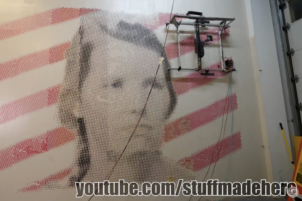
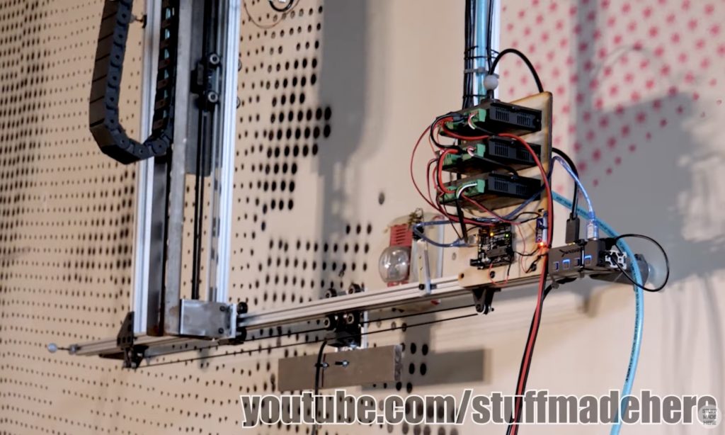
Driven by a desire to print massive pieces of art on his new studio’s blank wall, Shane Wighton of the YouTube channel Stuff Made Here set out to create a large painting robot, which he calls “Janksy” after the famous artist and the jankiness of the construction.
In principle, the device works by using a large gantry that spans the entire length of the wall to move horizontally while a series of cables and pulleys move it vertically. To avoid vibrations caused by moving such a large amount of weight so quickly, a second and far smaller/faster gantry houses a spray nozzle that deposits paint dots. All of this hardware is controlled by an Arduino Uno that translates positional commands into movements for the onboard stepper motors and servo.
Generating the dot array is done by first taking the initial digital image and converting it into four layers that each correspond to cyan, yellow, magenta, and black, just like a traditional inkjet printer. From there, every dot is scaled based on the intensity of the color, with larger dots appearing brighter and smaller ones showing up as dimmer.
After painting the wall over the course of several days, Wighton’s mural of his wife’s signature glare was complete. And even though it doesn’t look like much up close, taking a few steps back makes the entire thing come alive — imperfections and all.
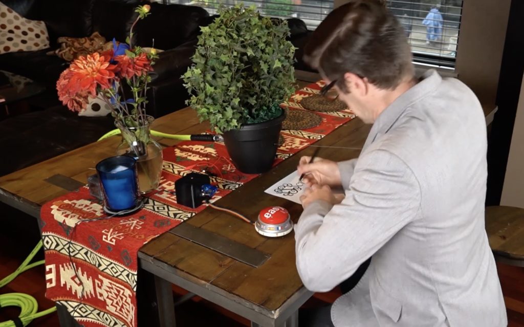
Everyone needs a little kick in the pants to stay motivated every now and then. With so many of us working from home, where bosses aren’t looking over our shoulders, that is truer now than ever before. Hardware Unknown’s Focus Flower gives that kick in the pants in the form of liquid motivation blasting your face.
Focus Flower’s operation is as simple as possible. When it’s time to start a new task, push the big red “easy” button. A bigger will begin its countdown, giving you a set amount of time to complete your task. Once you do, push the button again for a congratulatory auditory back pat. But if you don’t complete the task in time, that innocuous potted plate on your desk will shoot a jet of water at you. It’s good ol’ fashioned negative reinforcement.
That easy button connects to an Arduino Nano board in a small black enclosure. That enclosure also includes an arming switch, in case you’re not in the mood for damp motivation. The Arduino controls a solenoid valve that resides in the plant’s pot along a water reservoir. When the valve opens, water shoots out of a nozzle using the pressure coming from any conveniently-located air compressor. To provide the hardworking user with some indication of the time remaining, the easy button has a ring of LEDs.
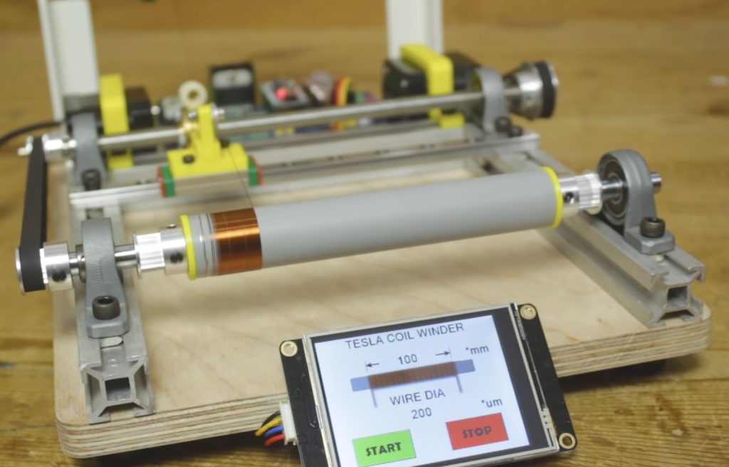
Winding a single strand of wire onto a cylinder when creating a homemade coil can be a very tedious process, and worse, the spacing between each rotation is inconsistent or has overlaps rather than a smooth, even surface. To make things a bit more easier and efficient, YouTuber Mr. Innovative created a DIY machine that accomplishes the task with very little human involvement.
The core of the device is an Arduino Nano, which is connected to a pair of A4988 stepper motor drivers and a screen, all mounted onto a custom PCB. The 3.5” LCD functions as a touch display that lets the user select both the length of the wrapping and the width of the wire. This allows the number of windings to be calculated by dividing the length (such as 100mm) by the wire’s diameter (such as 200um for a total of 500 windings).
With the figure calculated, the first stepper motor spins the attached cylinder to wind on the wire. While that happens, a secondary stepper turns a threaded rod that moves the head across the cylinder at a fixed rate. The resulting coil has a smooth, even finish that nearly any hobbyist would be proud of, and better yet, it was created automatically.
For more details on this project, you can view Mr. Innovative’s video below.
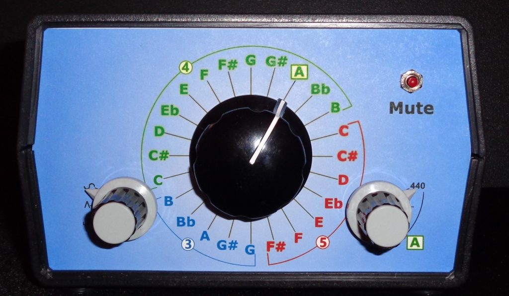
Electronic instrument tuners have existed now for several decades, but the ones with a great amount of precision can cost over a thousand dollars to the consumer, which is far above what many are willing or able to pay. To address this issue of high prices while still maintaining a high degree of accuracy, Jan Herman built his own device that utilizes just a few relatively common parts.
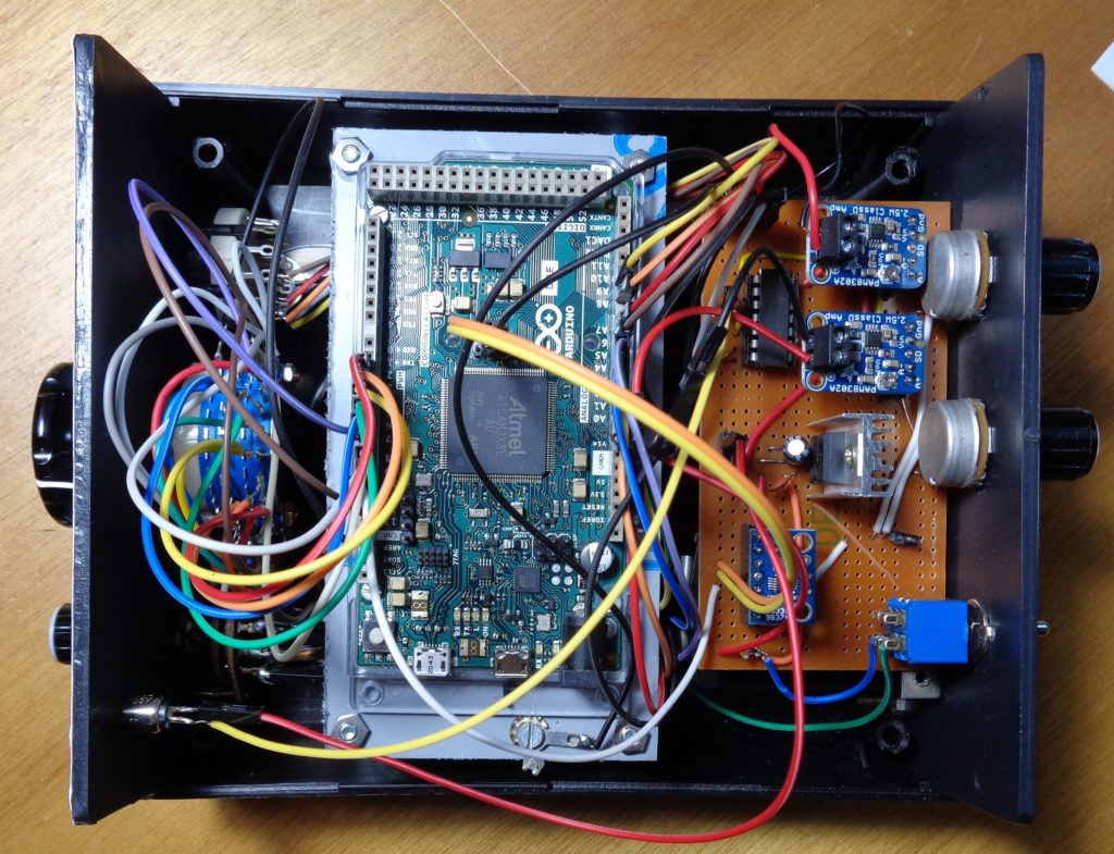
Within the housing of his tuner is an Arduino Due, which was selected because of its 32-bit architecture (for precision when measuring frequencies), faster speeds, and a large amount of GPIO pins. Apart from that, Herman included an AD9833 waveform generator breakout, a PAM8302 amplifier circuit, a pair of rotary potentiometers and switches for getting user inputs, and a transducer/speaker setup along with various passive components for power input.
Initially, Herman had planned to include a small speaker that would listen for feedback from the instrument and give the tuner an amount to adjust the string by. However, this proved to be too costly, thus why the transducer and speaker combination was chosen instead. When the user of this project wishes to adjust the frequency, they simply listen to the wave generator and attempt to match it.
BMWs are known for many things: performance, luxury, quality, and pedigree. But BMW drivers are only known for one thing: being inconsiderate to others on the road. That stereotype is exemplified by a complete lack of turn signal usage, according to Marc Radinovic. To solve this issue and repair the reputation of BMW drivers, he turned to Arduino to create a training device.
Radinovic attached this device to his own car, which he didn’t want to hack apart. So he avoided tapping into the CAN bus by utilizing an abundance of hardware. That hardware includes two Nano 33 BLE boards, an Uno WiFi Rev. 2, and a Raspberry Pi single-board computer. Each Nano 33 BLE has an integrated 9-axis IMU, which Radinovic uses to detect steering wheel movement and turn signal stalk movement.
Both Nano 33 BLE boards communicate with the Uno WiFi board, which connects to the Raspberry Pi via serial. If the steering wheel moves without the turn signal stalk moving, the Arduino Uno WiFi tells the Raspberry Pi to play an angry sound effect through the car’s stereo. That’s the negative reinforcement in the training regimen. The positive reinforcement comes from playing congratulatory sound effects when the driver uses their turn signal before turning the steering.
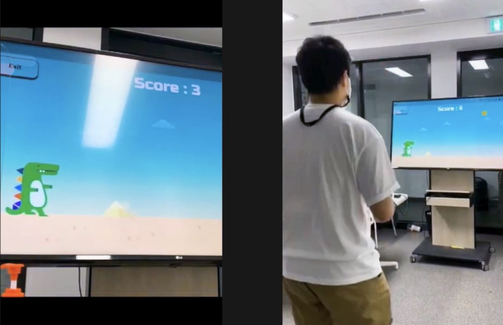
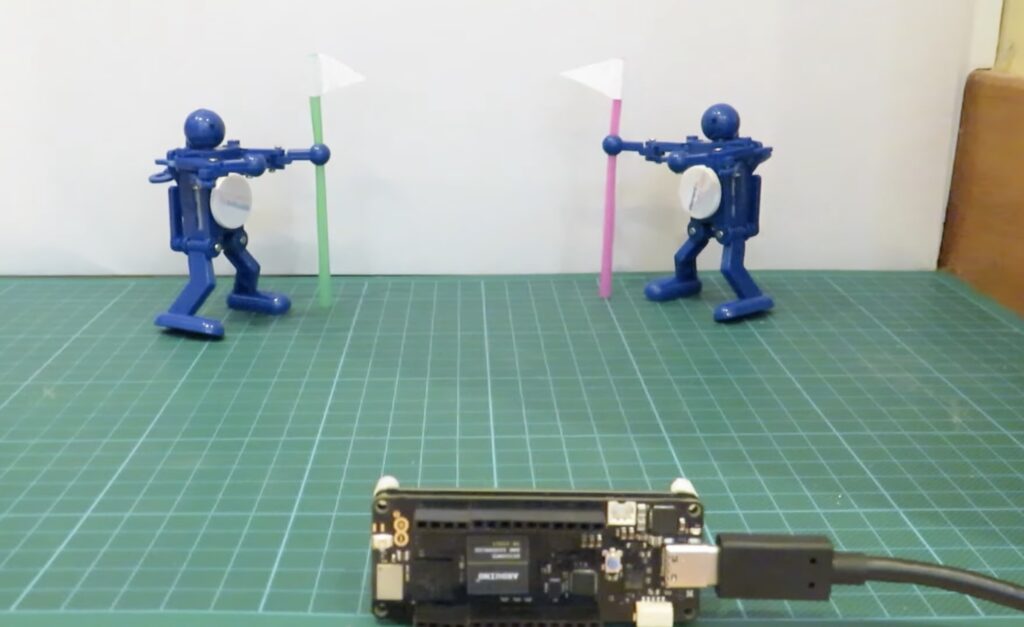
Gamifying exercise allows people to become more motivated and participate more often in physical activities while also being distracted by doing something fun at the same time. This inspired a team of students from the Handong Global University in Pohang, South Korea to come up with a system, dubbed “Move!,” that uses a microcontroller to detect various gestures and perform certain actions in mobile games accordingly.
They started by collecting many different gesture samples from a Nano 33 BLE Sense, which is worn by a person on their wrist. This data was then used to train a TensorFlow Lite model that classifies the gesture and sends it via Bluetooth to the host phone running the app. Currently, the team’s mobile app contains three games that a player can choose from.
There is a dinosaur game that operates similarly to the offline dinosaur game in Google Chrome where the user must jump to avoid incoming obstacles. The jumping jack game alternates between different movements that are mirrored by the player in a certain amount of time. And finally, there is a boxing game where the player punches the air when commanded onscreen.
You can read more about Move! — which was one of the five winning projects in the TensorFlow Lite for Microcontrollers Challenge — here and view/download the code for both the BLE Sense and mobile app on GitHub.
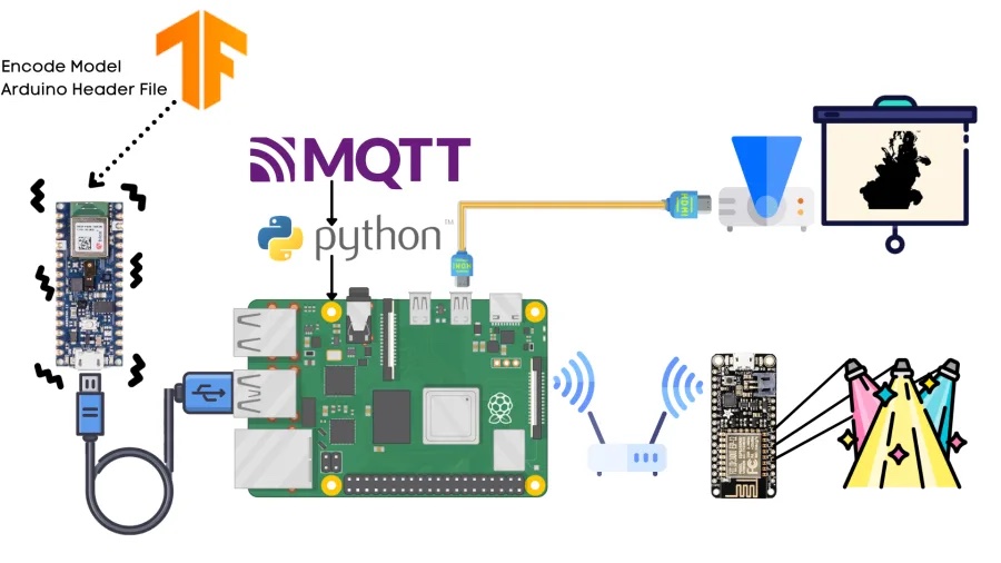
Being able to add dynamic lighting and images that can synchronize with a dancer is important to many performances, which rely on both music and visual effects to create the show. Eduardo Padrón aimed to do exactly that by monitoring a performer’s moves with an accelerometer and triggering the appropriate AV experience based on the recognized movement.
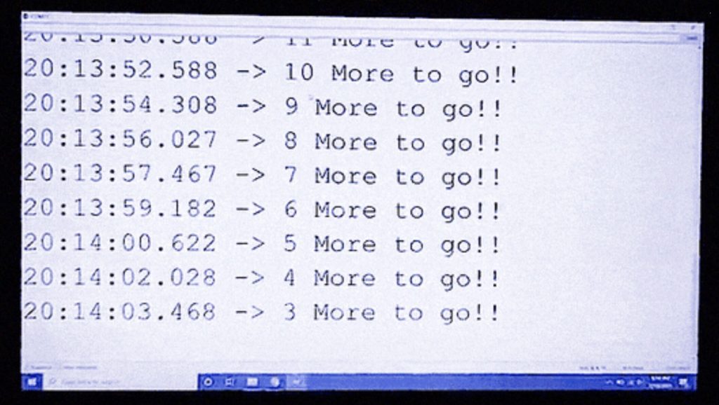
Padrón’s system is designed around a Raspberry Pi 4 running an MQTT server for communication with auxiliary IoT boards. Movement data was collected via a Nano 33 BLE Sense and its onboard accelerometer to gather information and send it to a Google Colab environment. From here, a model was trained on these samples for 600 epochs, achieving an accuracy of around 91%. After deploying this model onto the Arduino, he was able to output the correct gesture over USB where it interacts with the running Python script. Once the gesture is received, the MQTT server publishes the message to any client devices such as an ESP8266 for lighting and plays an associated video or sound.
Getting in your daily exercise is vital to living a healthy life and having proper form when squatting can go a long way towards achieving that goal without causing joint pain from doing them incorrectly. The Squats Counter is a device worn around the thigh that utilizes machine learning and TensorFlow Lite to automatically track the user’s form and count how many squats have been performed.
Creator Manas Pange started his project by flashing the tf4micro-moition-kit code to a Nano 33 BLE Sense, which features an onboard three-axis accelerometer. From there, he opened the Tiny Motion Trainer Experiment by Google that connects to the Arduino over Bluetooth and captures many successive samples of motion. After gathering enough proper and improper form samples, Manas trained, tested, and deployed the resulting model to the board.
Every time a proper squad is performed, the counter ticks down by one until it reaches a predefined goal.
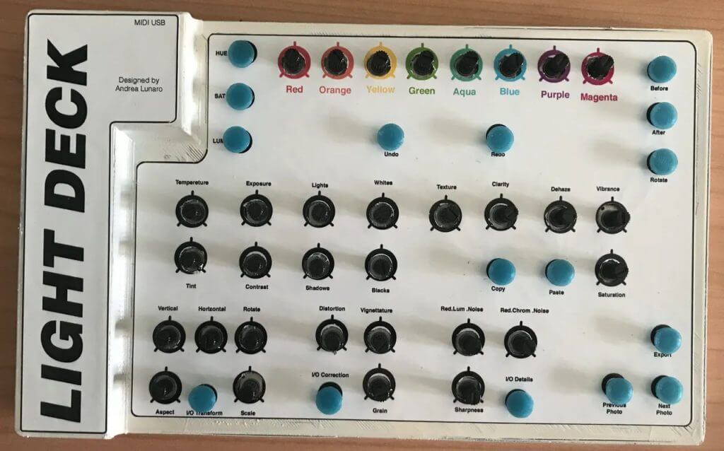
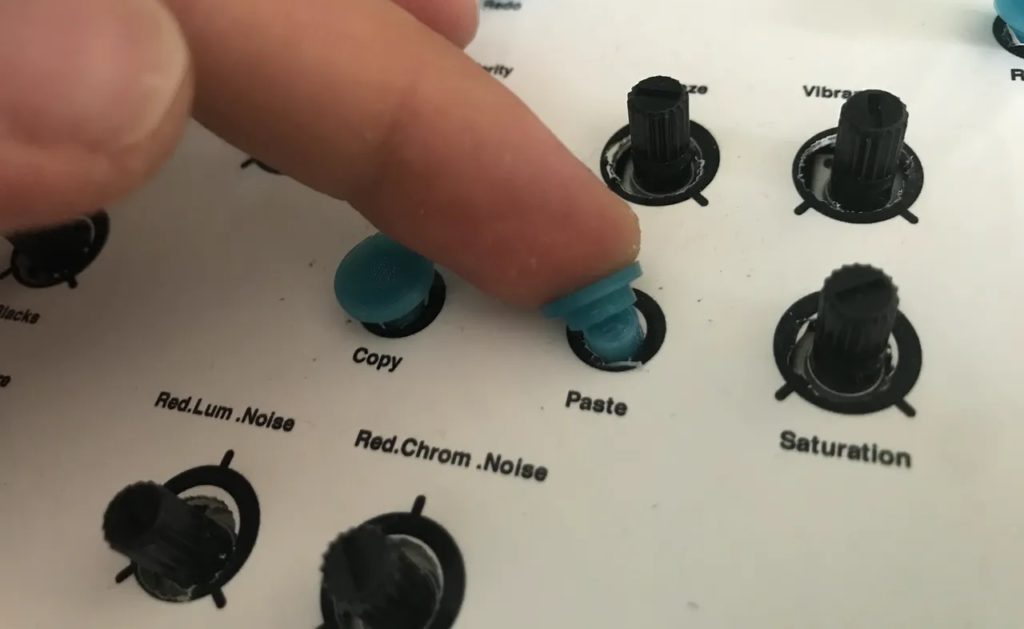
Using Adobe Lightroom can be a tedious process, especially for those who don’t have their keyboards set up with a hundred macro shortcuts. Andrea Lunaro wanted to make this process easier by constructing a large, physical bank of buttons and potentiometers that can be used to perform a whole host of functions within Lightroom. It can output commands to copy/paste, set HSL values, do basic transformations, and navigate around the software in general, all over the MIDI protocol.
This device — called the Light Deck — is powered by a single Arduino Micro, which is connected to several 16-channel 74HC4067 multiplexer ICs that handle both the input and output with the bank of rotary potentiometers and buttons. Data is outputted via USB to the host computer running Lightroom where it is then converted to Lightroom commands with the help of the MISI2Lr plug-in.
Both the PCB and enclosure were custom-designed and assembled, with the enclosure being fully 3D-printed along with its accompanying button/potentiometer covers. As seen in this demonstration video, the Light Deck works really well at providing users with a pleasant analog interface for fine-tuning various image parameters.
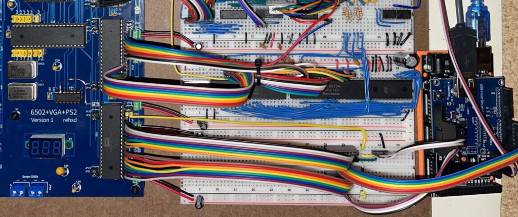
The MOS Technology 6502 was one of the most popular processors of the 8-bit era. It found a home in legendary computers like the Commodore 64, Acorn Electron, BBC Micro, and Apple II. Even the NES had a custom implementation of the 6502. Because the 6502 is so well documented, it is possible for today’s enthusiasts to use it in their own homebrew computers. To enhance their DIY 6502 computer, rehsd used an Arduino to add USB mouse support.
This homebrew computer is a Ben Eater design, which rehsd modified and created a PCB to streamline. It operates like most computers from the late ’70s and early ’80s. Computers back then didn’t support USB mice — the USB standard wouldn’t even exist until 1996. Joysticks were common, but graphical user interfaces and the mice to support them were not. So rehsd had to find a way to get a USB mouse talking to his 6502 processor. They settled on an Arduino Mega as an adapter.
The mouse connects to the Arduino through a USB host shield, which lets the board read data coming from standard USB devices. The Arduino runs a sketch that polls the mouse data and then sends that data to the 6502 through the VIA (Versatile Interface Adapter). It first triggers interrupts on the VIA and then writes the mouse data to the VIA ports. Code written in assembly runs on the 6502 and reads the mouse data after the interrupts. To demonstrate the mouse, rehsd wrote a simple drawing program that would have been a hit in 1978.
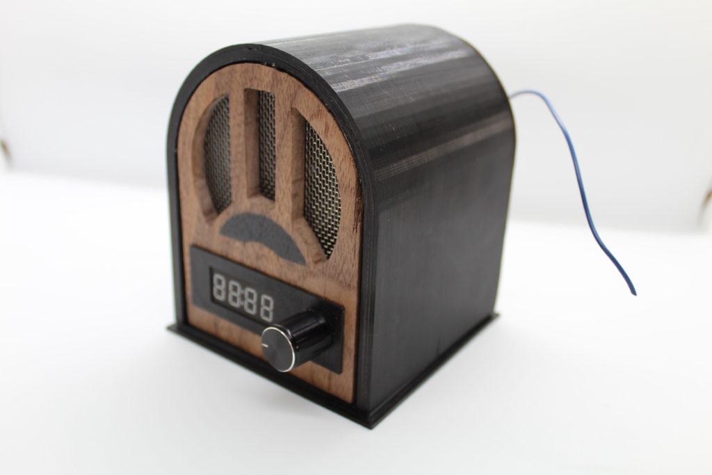
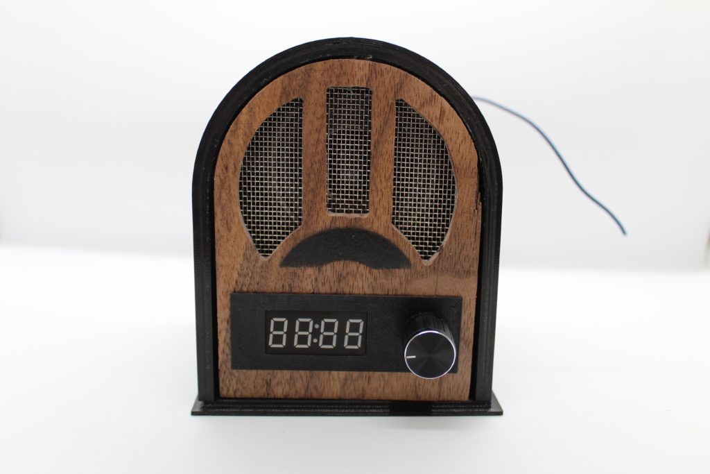
As time has progressed, personal radios have shrunk from the size of a large filing cabinet down to a tiny circuit that can be integrated into other ICs. Instructables user exposedwire wanted to bring back the experience of a vintage 1920s radio set, so they built one out of wood that carries the same antique feeling with some more modern features.
For the electronics, exposedwire went with an Arduino Uno for the main control board, along with a TEA5767 FM receiver IC that communicates with the Uno over I2C. The currently tuned frequency is displayed on a seven-segment LED module, which is driven by the ubiquitous TM1637 chip. The station can be changed by rotating the accompanying rotary encoder. Finally, the resulting audio signal is sent from the TEA1637 to an NS8002 amplifier and outputted from a small speaker.
The outer shell of the enclosure was fabricated by first 3D printing an arch-like structure and gluing it to the back wooden cover. After the speaker was set into its mount, the wooden faceplate was attached along with its speaker grill and front panel assembly. The FM radio antenna simply sticks out the back next to the power input jack.
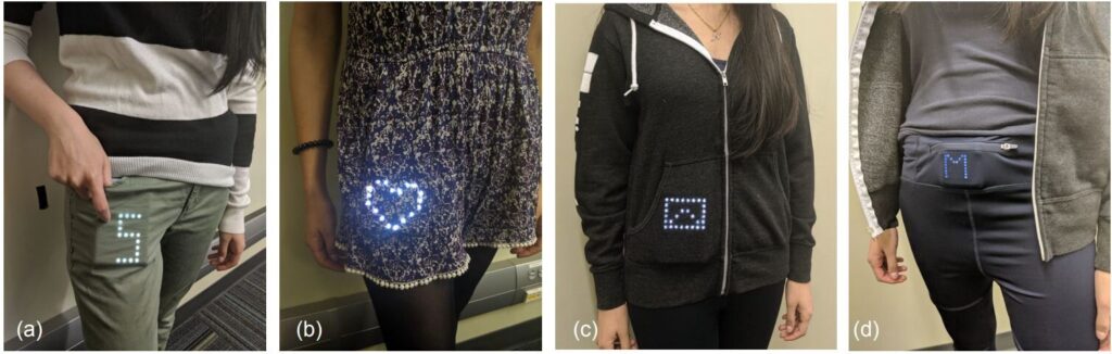
When receiving a notification on your phone, it can be a tedious process to take the device out of a pocket, unlock the screen, and then read the message. In order to make viewing simple information much faster, University of Waterloo researchers developed a small pocketable display that can shine images and text through fabric. This means seeing the current time or directions can be done far more quickly since all the user has to do is look down.
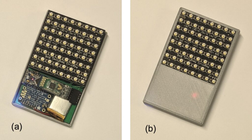
The technology driving this system consists of an Arduino Pro Mini board, an HC-05 Bluetooth module for receiving data from a host phone, an 8×8 RGBW NeoPixel matrix, and a single 420mAh LiPo battery cell for power. All of these components were assembled into a single unit and placed within a 3D-printed enclosure that can easily fit into the user’s pocket.
After studying how LEDs interact with various types of fabrics by using an Arduino Mega, the team gathered 12 participants to see how effective their smart display, called the PocketView, was at showing important information. Once several tasks had been performed by the group, they consistently rated the LEDs to be a better viewing experience compared to looking at a phone.
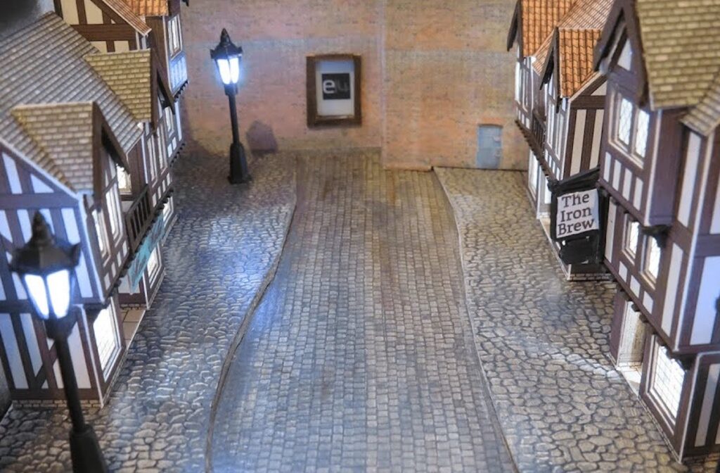
The fantastical world of wizards and magic is one that can be explored by reading a book, and what better way to represent this than building your very own interactive diorama within a reading corner? Well, that is exactly what Andy of element14 Presents created when he combined a small display, computer vision, and LED lights into a fun bookshelf adornment, which would accompany readers on their journeys.
To begin, Andy had to figure out how to get a computer vision system into a space that is no larger than a shoebox, and for this task, he settled on using the Portenta H7 board plus its Vision Shield to gather images and classify them. His attempts to integrate a string of NeoPixels and an ePaper display module with MicroPython were unsuccessful, so this required a switch to only using C with TensorFlow Lite and some custom functions to take the framebuffers from the camera and determine if a face is present.
The diorama models themselves were fashioned from cardboard model railway kits that included houses and a few streetlights. Finally, the LEDs were added both behind the houses and inside of each lamppost that allows them to flicker and light up when a person is watching the display. The ePaper module switches between various stills such as a wanted poster and the element14 logo.
To see more about how this diorama was constructed, check out Andy’s video below!
Um dir ein optimales Erlebnis zu bieten, verwenden wir Technologien wie Cookies, um Geräteinformationen zu speichern und/oder darauf zuzugreifen. Wenn du diesen Technologien zustimmst, können wir Daten wie das Surfverhalten oder eindeutige IDs auf dieser Website verarbeiten. Wenn du deine Einwillligung nicht erteilst oder zurückziehst, können bestimmte Merkmale und Funktionen beeinträchtigt werden.
Funktional
Immer aktiv
Die technische Speicherung oder der Zugang ist unbedingt erforderlich für den rechtmäßigen Zweck, die Nutzung eines bestimmten Dienstes zu ermöglichen, der vom Teilnehmer oder Nutzer ausdrücklich gewünscht wird, oder für den alleinigen Zweck, die Übertragung einer Nachricht über ein elektronisches Kommunikationsnetz durchzuführen.
Vorlieben
Die technische Speicherung oder der Zugriff ist für den rechtmäßigen Zweck der Speicherung von Präferenzen erforderlich, die nicht vom Abonnenten oder Benutzer angefordert wurden.
Statistiken
Die technische Speicherung oder der Zugriff, der ausschließlich zu statistischen Zwecken erfolgt.Die technische Speicherung oder der Zugriff, der ausschließlich zu anonymen statistischen Zwecken verwendet wird. Ohne eine Vorladung, die freiwillige Zustimmung deines Internetdienstanbieters oder zusätzliche Aufzeichnungen von Dritten können die zu diesem Zweck gespeicherten oder abgerufenen Informationen allein in der Regel nicht dazu verwendet werden, dich zu identifizieren.
Marketing
Die technische Speicherung oder der Zugriff ist erforderlich, um Nutzerprofile zu erstellen, um Werbung zu versenden oder um den Nutzer auf einer Website oder über mehrere Websites hinweg zu ähnlichen Marketingzwecken zu verfolgen.