Schlagwort: tech

  • Dial up your PCB design skills with an LED volume control shield

    Dial up your PCB design skills with an LED volume control shield

    Reading Time: 2 minutes

    Arduino TeamJuly 10th, 2022

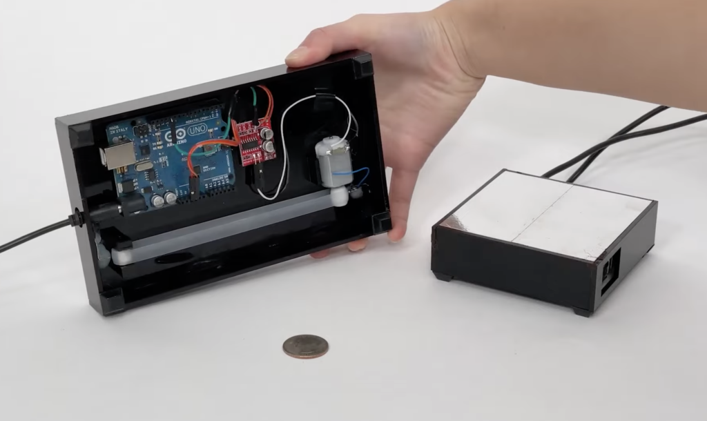
    The beauty of Arduino development boards is that they let you jump right into prototyping. Just connect the sensors, buttons, LEDs, or whatever other hardware you require to the Arduino’s I/O pins, code and flash a sketch, and you’re in business. But you might come to a stage where you want something more polished than a breadboard or perfboard. When you reach that stage, you can follow along with YouTuber Upir’s LED volume knob project to learn how to design your first PCB. 

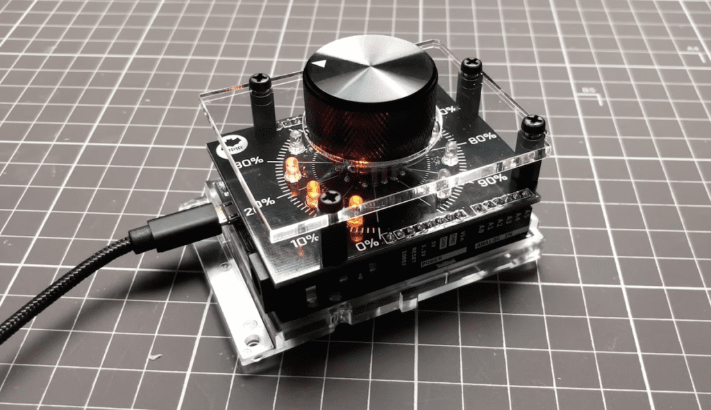
    Upir chose to use an Arduino Leonardo board for this project because its ATmega32U4 microcontroller’s built-in USB HID functionality. That means that it can be configured to show up as a USB mouse or keyboard when plugged into any computer, regardless of the operating system or software that computer runs. In this case, that makes it easy to send keyboard shortcuts that adjust the computer’s volume. 

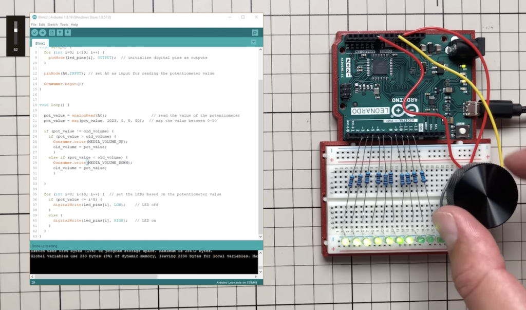
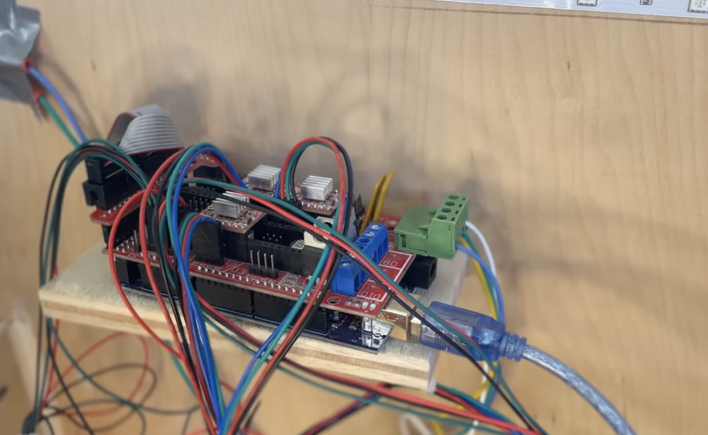
    The hardware for this project, in addition to the Leonardo itself, consists of a potentiometer knob, LEDs, and resistors. The sketch sets the number of lit LEDs to correspond to the current volume level. Upir first prototyped the circuit on a breadboard to test the Sketch and functions. Then he designed a dedicated PCB shield for the Arduino. In his video below, Upir goes into detail on every step of the PCB design process in open source KiCAD software. This information is valuable to anyone interested in learning how to create their own PCBs.

    [youtube https://www.youtube.com/watch?v=6cqvTHCuDto?feature=oembed&w=500&h=281]

    If you follow Upir’s instructions, either for this project or a similar design, you’ll end up with a set of files that you can send to any PCB fabrication service to get professional-quality boards.

    [youtube https://www.youtube.com/watch?v=jvHRfsgw4l8?feature=oembed&w=500&h=281]

    Website: LINK

  • This small Space Invaders game runs on an Arduino Nano with a salvaged CRT display

    This small Space Invaders game runs on an Arduino Nano with a salvaged CRT display

    Reading Time: 2 minutes

    Arduino TeamJuly 6th, 2022

    Rob Cai over on Instructables has created his own version of the classic video game Space Invaders using an Arduino Nano. However, unlike most other projects that would typically incorporate some kind of LCD or OLED screen, he chose to use a small black and white cathode ray tube (CRT) display recovered from an old video intercom system.

    As his first step, Cai needed to locate the analog-only video input on the salvaged screen as well as find its rated supply voltage. From here, he built a very minimalistic tiny arcade cabinet out of cardboard and used hot glue to join the panels together. But before he could assemble anything, Cai wrote his port of Space Invaders by designing several kinds of 2D sprites and loading them into a few arrays. Outputting a video signal was accomplished via the use of the TVout library, which takes an array of pixels and writes them sequentially to the designated RCA video output pin, as well as syncing each frame with a secondary pin.

    The controls for the game are comprised of five buttons, with four on the left for moving in a certain direction, and the last one on the right for firing the player’s laser upwards. For more information about how Cai built this mini Space Invaders arcade cabinet, you can read his guide here or watch the demo video below!

    [youtube https://www.youtube.com/watch?v=18uQas8b6kk?feature=oembed&w=500&h=281]

    Website: LINK

  • Reviving a classic Sony PS-X75 record player with Arduino

    Reviving a classic Sony PS-X75 record player with Arduino

    Reading Time: 2 minutes

    Arduino TeamJuly 6th, 2022

    In 1979, Sony launched the PS-X75 turntable. It quickly gained popularity thanks to its high-fidelity sound output and ease of use. It was easy to use because it was fully automated–a common feature today, but something that was quite exciting at the time. To perform that automation, the PS-X75 contained an integrated circuit that detected record size, dropped the needle, and so on. But that IC was prone to failure. To revive their Sony PS-X75 turntable, MKB-1 used an Arduino Mega to replace the original circuit.

    Unlike earlier turntable designs, which were often entirely electromechanical, the PS-X75’s IC controls almost all of the turntable’s functions digitally. That means that when the IC fails, the turntable becomes inoperable. Replacement ICs are almost impossible to find and haven’t been manufactured in many years. For most people, this means that the PS-X75 becomes e-waste when that IC bites the dust. But MKB-1 has some reverse-engineering skill and was able to save their PS-X75 by swapping out original IC for an Arduino Mega.

    MKB-1 was able to achieve this impressive feat by carefully studying the original PS-X75 service manual, which included detailed schematics and details on each function’s electrical operation. With this info, they replicated all 42 of the original IC’s connections on an Arduino Mega 2560 development board. They chose the Mega because it had enough I/O pins available to handle all of those connections. Their custom Sketch handles all of the original functionality, from reading button presses to lowering the tone arm. If you own a PS-X75, MKB-1’s detailed Instructables tutorial will walk you through how to perform this retrofit. 

    [youtube https://www.youtube.com/watch?v=31ILr8oTtt4?feature=oembed&w=500&h=281]

    Website: LINK

  • Love LoRa®? So do we! Meet Arduino’s WisGate LoRaWAN® gateways

    Love LoRa®? So do we! Meet Arduino’s WisGate LoRaWAN® gateways

    Reading Time: 3 minutes

    Love LoRa®? Wish it were easier to design and implement complete solutions with LoRaWAN® connectivity? Now it is.

    We’re happy to announce the launch of two new ready-to-use, industrial-grade gateways for LoRaWAN® connectivity for indoor and outdoor use, resulting from Arduino Pro’s partnership with RAKwireless™

    The WisGate Edge Lite 2 and WisGate Edge Pro ensure secure and reliable connectivity for a wide range of professional applications. They’re suitable for medium-sized to wide area coverage in industrial environments and remote regions. Smart cities and smart agriculture to logistics and building automation. The sky’s the limit!

    The WisGate Edge Lite 2 offers deep coverage indoors, ideal for applications in multi-story buildings, and features an enclosure designed for efficient cooling with optional DIN rail mounting. The WisGate Edge Pro on the other hand, with its high transmission power and dual fiberglass antennas with 5dBi gain, is the perfect fit for IoT commercial outdoor deployment, and comes with a kit for on-pole and DIN-rail installation. In addition, the WisGate Edge Pro supports up to 16 LoRa® channels thanks to a Dual LoRaWAN® Concentrator, while the WisGate Edge Lite 2 provides eight channels.

    The two gateways offer solid performance and our signature user-friendly approach. Designed to boost your innovation potential, they offer an intuitive user experience, easy setup and diagnostics, exhaustive tutorials and technical documentation for both the WisGate Edge Pro and the WisGate Edge Lite 2, and hassle-free mounting accessories.

    These newest additions to our growing family of hardware products complement the MKR and Portenta SOM boards, the Arduino IoT Cloud platform and our other LoRa® components with the additional features you’ve been waiting for, to easily integrate one of the leading IoT access standards into your projects.

    Pole mounted WisGate Edge Pro

    WisGate Features

    • Secure Ethernet, Wi-Fi or LTE connectivity
    • High transmission power and dual fiberglass antennas with 5dBi gain (WisGate Edge Pro only)
    • Choose the coverage you need: WisGate Edge Lite 2 for deep coverage in multi-story buildings, or WisGate Edge Pro for IoT commercial outdoor deployment
    • Rapid setup and diagnostics, backup and data logging thanks to an SD card slot
    • WisGateOS, powered by RAKwireless™, based on the fully customizable, open-source OpenWRT
    • Ideal for implementing private networks directly connected to cloud platforms; compatible with public networks
    • Limited cabling for installation thanks to POE (Power Over Ethernet)
    • Comprehensive technical documentation by RAKwireless™
    • Easy installation: WisGate Edge Lite 2 comes with an enclosure designed for efficient cooling and optional DIN rail mounting; WisGate Edge Pro includes an on-pole and DIN-rail installation kit

    You can explore the tech specs more in detail on the Store for the WisGate Edge Lite 2 and WisGate Edge Pro. Or feel free to contact us at Arduino Pro for custom support.

    If you plan on attending the LoRaWAN® Alliance World Expo in Paris (July 6-7, 2022), come visit us at RAKWireless™’s Booth 36A. Our team there will be showing the new gateways for the first time and will be happy to answer any questions.

    In the meantime, take a closer look at the WisGate gateways right here on Arduino Pro.

    Website: LINK

  • Brenda is classic automata nightmare fuel

    Brenda is classic automata nightmare fuel

    Reading Time: 2 minutes

    Arduino TeamJuly 5th, 2022

    Art is a strange thing. Sometimes its purpose is purely aesthetic. Sometimes it makes a statement. And sometimes it exists to disturb. Kinetic art is no different and some robots fall into this category. Graham Asker’s art elicits pondering on the relationship between humans and robots, as well as the relationships between different robots. But as Brenda, a classical-style automaton, demonstrates, Asker’s art can also induce nightmares.

    Brenda and her companion Brian are strange, bodiless robots designed to mimic the aesthetics of automatons from myth and history. Each robot is a construction of beautiful brass, mechanical joints, linkages, and cables. Servos hidden inside the bases of the robots actuate the various joints, giving Brenda and Brian the ability to emote. Most of their “facial” movement is in their eyes. Lifelike eyeballs look around from within heavy eyelids, while pivoting eyebrows help to convey expressions.

    Arduino boards, also hidden within the robots’ bases, control the servos that actuate the joints. Asker programmed the Sketches with a variety of different servo movements that correspond to facial expressions and eye movements. Brenda even received lips, so she can smile – or frown. Both robots’ bases rotate, so the robots can turn to look at their surroundings. Brenda and Brian do not have any communications hardware and so they can’t interact with each other, but Asker can sync their pre-coded movements to create the illusion that they do.

    Asker, who is a retired engineer with a Master’s degree in fine art, displayed Brenda at London’s Espacio Gallery and on the Walthamstow Art Trail.

    Website: LINK

  • This device predicts when a refrigerator might fail using embedded ML

    This device predicts when a refrigerator might fail using embedded ML

    Reading Time: 2 minutes

    Arduino TeamJuly 4th, 2022

    The refrigerator is one of the centerpieces in a modern kitchen, and experiencing a loss in cooling can lead to hundreds or even thousands of dollars of spoiled goods. Perhaps even more importantly, a sudden loss of medications or vaccines that heavily rely on refrigeration can heave a big impact on the people that need them. Swapnil Verma wanted to solve this problem, so he came up with an idea to incorporate a simple machine learning model into a device that could monitor for failures.

    When gathering datapoints for training the model, Verma began by identifying different failure modes, such as a decrease in temperature, change in humidity, or simply an abnormality. He opted to use an Arduino Nano 33 BLE Sense along with its built-in temperature/humidity and ambient light sensors. From here, data is streamed over Bluetooth® LE to a Portenta H7 and logged to a microSD card. Verma then uploaded the resulting CSV files to Edge Impulse Studio and trained an anomaly detection model that could recognize when conditions inside the refrigerator are incorrect.

    Although the deployment doesn’t currently involve sending alerts, Verma did suggest that the feature could be added in the future, especially for the medical field. Want to dive into the details of project? Check out his tutorial on Edge Impulse as well as here in the Edge Impulse Studio.

    Website: LINK

  • This DIY basketball scoreboard looks and sounds like the real thing

    This DIY basketball scoreboard looks and sounds like the real thing

    Reading Time: 2 minutes

    Arduino TeamJuly 3rd, 2022

    Inspired by his time as a scorekeeper in elementary school, now-high schooler Collin Wentzien wanted to recreate this setup by building a DIY scoreboard several years ago. His idea involved making a bright display composed of several seven-segment displays that could all be controlled by an external device in order to set scores, start/stop the clock, and more.

    The controller sits inside of a small custom box that contains a pair of button matrices, which either increment the score for the home/guest team or provides a keypad that can be used to enter numerical values and set the clock. Below its custom PCB is an Arduino Mega 2560 that handles all of the button inputs, along with a character LCD for showing what has been entered and an nRF24L01+ wireless transceiver for sending new data to the scoreboard.

    Originally, Wentzien had planned on using hundreds of individual LEDs, but due to the resulting wiring complexity, instead opted for a single string of WS2812B LEDs which were not only cheaper, but also allowed for fun animations and colors. Similar to the controller, the scoreboard houses an Arduino Uno as well as an nRF24L01+ in order to receive the commands. Best of all, the it even features a loud horn that can be used to signal the start and end of each quarter.

    To see how Wentzien built this highly interactive project, you can read his write-up here on Hackster.io or watch his video below!

    [youtube https://www.youtube.com/watch?v=zdeKpxZJ_U0?feature=oembed&w=500&h=281]

    Website: LINK

  • Arduin-Row uses tinyML to improve your rowing technique

    Arduin-Row uses tinyML to improve your rowing technique

    Reading Time: 2 minutes

    Arduino TeamJuly 2nd, 2022

    Rowing machines make for excellent aerobic workouts, as they involve repeatedly pushing one’s legs against the base and pulling out the handle to achieve the fastest times. But because of the equipment’s nature, learning how to exercise correctly on one often requires a coach that can correct the user’s form, which is why Justin Lutz created the Arduin-Row.

    The Arduin-Row uses the accelerometer and Bluetooth® Low Energy capabilities found on the Nicla Sense ME board that has been mounted as a shield on top of an Arduino MKR WiFi 1010. To gather data for his machine learning model, Lutz took advantage of Edge Impulse’s Data Forwarding tool in order to capture the data and send it to the Edge Impulse Studio. From here, he labeled each sample as either “easy,” “hi-spm,” or “low-spm,” and trained a Keras model that could successfully recognize the current motion about 98% of the time.

    Lutz expanded the project even further by incorporating the Nicla’s onboard eCO2 sensor to plot an estimate of how much power is being generated by the rower. Once deployed, the code allows users to see a list of feedback given by the virtual coach and view a chart of their expended CO2 via the IoT Cloud Remote app.  

    [youtube https://www.youtube.com/watch?v=p3sivOERAvA?feature=oembed&w=500&h=281]

    You can read more abut the Arduin-Row on its Edge Impulse docs page or view the public project here in the Edge Impulse Studio.

    Website: LINK

  • DIY diesel emissions monitor is a lesson in spectroscopy

    DIY diesel emissions monitor is a lesson in spectroscopy

    Reading Time: 2 minutes

    Arduino TeamJune 30th, 2022

    Some things, like voltage, are very easy to measure. Other things, like the chemical composition of a compound? Not so much. Emissions from internal combustion engines are one of those things that are hard to measure. But Janis Alnis needed a way to measure his diesel soot emissions so he could pass inspections in his home country of Latvia. So he used an Arduino, spectroscopy expertise, and some plumbing hardware to build his own Diesel Car Exhaust Smoke Meter.

    As luck would have it, Alnis is a lead researcher at the Institute of Atomic Physics and Spectroscopy of the University of Latvia. That means that he knows his stuff when it comes to spectroscopy, which is a field that uses light for analysis of different materials—including gases like diesel exhaust. In this case, he needed to measure how much soot was in the exhaust, which would let him know if his catalytic converter was warmed up and working well enough to pass inspection.

    To do so, he built his own spectrometer that works in the same manner as the AVL DiSmoke 280 commercial instrument that the inspectors use. It consists of a light source and a photodetector at opposite ends of a 21.5cm long tube. When diesel exhaust fills the tube, the light that reaches the photodetector will dim proportionally with the soot in the exhaust.

    Alnis made the analysis tube using brass plumbing pipes. At each end is a custom-cut glass window. A small LED flashlight acts as the light source and an Arduino Uno board measures the strength of the light through an OPT101 photodiode with built-in amplifier. Power comes from three 18650 LiPo battery cells and the Arduino displays data readings on a 128×64 LCD screen. 

    With this device in hand, Alnis was able to measure his diesel emissions and determine when they were below the threshold required to pass inspections.

    Website: LINK

  • This large-format laser cutter was built from scratch for just $700

    This large-format laser cutter was built from scratch for just $700

    Reading Time: 2 minutes

    Arduino TeamJune 30th, 2022

    When stuck between a cheaper yet small laser cutter and splurging on a much larger one, Owen Schafer decided instead to just build one himself. The project started with Schafer sourcing a 40W CO2 laser, which differs from a diode laser in that it uses gas heated with 16,000 volts to produce a very powerful beam of light. This had the added side effect of needing a water-cooling system since the tube tends to generate ample amounts of heat.

    Once the laser and the necessary reflectors had been sourced, Schafer purchased aluminum extrusions and attached them with corner connectors. The head moves with the help of a gantry, wherein the X-axis slides along the Y-axis, and both are driven by NEMA17 stepper motors and a timing belt. For some added safety, he created a basic enclosure out of plywood just in case something went wrong internally.

    Each stepper motor is driven by an A4988 driver module, and all of them are controlled by an Arduino Mega 2560 loaded with the Marlin-based Marlaser laser cutter firmware. He even included a few LEDs strips within the enclosure that aid visibility and a simple ventilation system for fume extraction.

    After generating some toolpaths using Inkscape, the laser was finally able to cut nearly anything out of materials ranging from plastic to plywood. You can watch more about how Schafer brought this inexpensive laser cutter to life in the video below!

    [youtube https://www.youtube.com/watch?v=QtEF6c1t2tM?feature=oembed&w=500&h=281]

    Website: LINK

  • Building a simple USB adapter for the Logitech Driving Force Shifter with Arduino

    Building a simple USB adapter for the Logitech Driving Force Shifter with Arduino

    Reading Time: 2 minutes

    Arduino TeamJune 30th, 2022

    Logitech’s Driving Force Shifter is a very common piece of kit for those who enjoy racing games, as it connects to a Logitech Racing Wheel and allows the player to control their car in a more realistic fashion. However, this accessory’s DB-9 connector must be connected to a proprietary base within the racing wheel or else it fails to work. So as a way to circumvent this annoying problem, Parts Not Included’s Dave Madison created his own custom adapter, which translates the signals from the shifter into commands over a USB port on the host PC.

    To begin this endeavor, Madison purchased a DB-9 connector with the rear leads exposed, and after quickly modifying them, plugged the X/Y axis wires into analog input pins and connected the binary reverse pin into a digital input pin on the Arduino Leonardo. In terms of software, this setup requires both the Arduino Joystick library and the Sim Racing library. The latter converts X/Y values into shifter positions in order to determine the current gear, while the former communicates with the host as an emulated HID device.

    To read more about this project, you can visit Madison’s blog post here.

    [youtube https://www.youtube.com/watch?v=ngXsOidoWhI?feature=oembed&w=500&h=281]

    Website: LINK

  • eXaDrums is an open source, low-latency electronic drum system

    eXaDrums is an open source, low-latency electronic drum system

    Reading Time: 2 minutes

    Arduino TeamJune 29th, 2022

    For apartment-dwelling drummers, electronic drums are really the only option. While cheap electronic drum sets are on the market, they aren’t much more than noise-making toys. High-end sets, on the other hand, cost thousands of dollars. To make high-end hardware and software accessible to DIYers, Jeremy Oden developed an open source, low-latency electronic drum system called eXaDrums.

    Electronic drum sets consist of three major subsystems: the triggers (the drum pads that you strike), a trigger board that registers those strikes, and a processing unit. The processing unit can either pump out sound itself (through synthesis or sampling) or send a MIDI signal to an external system. The eXaDrums project contains all of this hardware, as well as the software to run it. Oden developed that software carefully to be operating system agnostic and to maintain a low latency so there is no audible delay between a beat and the sound output.

    The trigger board is a shield for Arduino Nano Every boards. The Nano Every is an affordable board, which keeps costs down. It can also read eight analog inputs at very fast speeds, which means it can support an entire kit’s worth of drum pads. That includes seven single-zone pads, plus an additional hi-hat. It can handle 9,000 samples per second, per channel.

    The Nano Every then sends MIDI notes via USB to a Raspberry Pi running the eXaDrums software. That software interprets the incoming MIDI signals and then outputs the sound that the user configures for the corresponding drum pad. All of that, along with a touchscreen interface, fits into a tidy 3D-printed enclosure that the user can attach to their electronic drum kit.

    Website: LINK

  • This project lets you experience life with a cybernetic tail

    This project lets you experience life with a cybernetic tail

    Reading Time: 2 minutes

    Arduino TeamJune 23rd, 2022

    Modern humans have forgone their tails in favor of walking upright, and this fact left maker Pengfei Zhang wondering what it would be like to have such an appendage. From this idea, she along with Sarvenaz Sardari and Xi Peng created the Cyber Tail, which integrates embedded electronics into a small device that moves with its wearer.

    The Cyber Tail’s design revolves around a central base that houses a set of four servo motors. In order to move the tail in various directions, each servo motor can either pull or release a single string, which causes the tail itself to bend, akin to how a finger works except in four possible directions. The Arduino Uno controlling these motions relies on an external IR sensor within a pair of glasses that detects whenever the user blinks.

    If a blink is recognized, two of the servo motors move in opposite directions to bend the tail in a particular way, and if a blink is not present, then they move in the other direction. Lastly, the MPU-6050’s accelerometer is read and used to compute the angles for the other two servo motors that also bend the tail. Put together, these three steps allow the Cyber Tail to move in a myriad of different ways.

    About 25 million years ago, our ancestors lost their tails during the evolution, to better adapt the the environment. As we are now living in the digital age, our bodies are evolving together with the cyber world. What would a cybernetic tail bring to our daily life? 

    For more information on this project, be sure to read the team’s write-up here on Instructables or watch their video below!

    [youtube https://www.youtube.com/watch?v=DBrxIYMtmmo?feature=oembed&w=500&h=375]

    Website: LINK

  • Monitoring IV fluid bag levels with the Arduino Portenta H7 and Vision Shield

    Monitoring IV fluid bag levels with the Arduino Portenta H7 and Vision Shield

    Reading Time: 2 minutes

    Arduino TeamJune 22nd, 2022

    When a patient is receiving intravenous (IV) fluids, it is vital that air is not introduced into the line, as its presence can create issues such as excessive pressure or even embolisms that can be life-threatening. Normally, the level of fluids remaining within the bag is periodically checked by a nurse, but due to challenges related to staffing, this might not be enough. Therefore, Manivannan Sivan devised an automated monitoring system that uses computer vision along with machine learning to do this repetitive task instead of a person.

    To begin the project, Sivan gathered a series of images that spanned three categories with an Arduino Portenta H7 and Vision Shield. Within each picture, the IV fluid bag is 15cm away and contains either an adequate, less than 50%, or low level of fluid remaining. Once trained, his model was able to successfully recognize the correct level around 96% of the time, although additional images taken at different light levels would help improve the accuracy even more.

    From here, Sivan deployed his model back to the Portenta H7 to see how it performs in day-to-day conditions, with classification taking place once every two seconds. His plan is to take the resulting category and export it to an awaiting server over the network so that hospital staff can see the fluid bag’s status in real-time on a dashboard.

    For more details on this project, you can watch Sivan’s explainer video below or read his write-up on the Edge Impulse docs page.

    [youtube https://www.youtube.com/watch?v=4W37gOTlnjk?feature=oembed&w=500&h=281]

    Website: LINK

  • This high-speed Arduino pen plotter creates drawings in mere minutes

    This high-speed Arduino pen plotter creates drawings in mere minutes

    Reading Time: 2 minutes

    Arduino TeamJune 21st, 2022

    Pen plotting projects are everywhere nowadays, with the vast majority using a couple of stepper motors for moving the writing utensil and a servo to raise or lower it. But they are quite slow due to the lack of rigid assembly and because the servo motor takes around a second to move the pen. This problem is what drove YouTuber IV Projects to create a very novel design that swaps out the servo for another stepper motor and drastically increases drawing speed.

    Just like most other pen plotters, the X-axis is driven by a NEMA17 stepper motor with a timing belt attached to the central pen carriage. However, the Y-axis takes a different approach by relying on a pair of rollers that are covered in 120-grit sanding bands, which help to grab the paper securely and move it whenever the stepper motor rotates the drive wheel. This helps to minimize slipping compared to rubber rollers and is much faster than a belt-driven design.

    Perhaps the most interesting aspect of this plotter is the lack of a servo motor for lifting the pen during travel movements. At the top sits one more NEMA17 stepper that spins upwards or downwards to lift a paddle which, in turn, raises the pen off the paper. Controlling the three motors is an Arduino Uno running the GRBL firmware that receives G-code and transforms it into physical movements.

    You can watch IV Projects’ video to below see the design in more detail.

    [youtube https://www.youtube.com/watch?v=wX90X4rVUr8?feature=oembed&w=500&h=281]

    Website: LINK

  • Designing a DIY watch with a brass ‘cyberpunk-y’ aesthetic

    Designing a DIY watch with a brass ‘cyberpunk-y’ aesthetic

    Reading Time: 2 minutes

    Designing a DIY watch with a brass ‘cyberpunk-y’ aesthetic

    Arduino TeamJune 20th, 2022

    The cyberpunk aesthetic, like several other genres, often takes the form of heavy and metallic body modifications or devices that are meant to signify a more futuristic society. Inspired by the video game Deus Ex, Redditor Star_11 had the idea to create their own smartwatch primarily out of soldered brass sheets and 3D-printed plastic.

    Within this space-age bracelet is an Arduino Nano Every, which controls the connected Crystalfontz SSD1320 flexible OLED display. On it, the watch can currently show the time and date, although other information such as the level of the 280mAh battery, alarms, and timers might be added in the future. Star_11’s plan is to also take a Nano 33 IoT and replace the Nano Every for extra IoT functionality or connect to a phone via Bluetooth®.

    Although the watch’s three-pin magnetic pogo connector appears to be used for recharging the device, Star_11 intended it for use with a custom input ring that slips around the wearer’s finger and houses a single pushbutton. However, later iterations might swap this out for a small joystick so that the GUI is easier to navigate.

    To see more about how Star_11 built this cyberpunk-themed smartwatch, head over to their Reddit post here.

    Website: LINK

  • This RGB wedding dress mimics Princess Aurora’s from Sleeping Beauty

    This RGB wedding dress mimics Princess Aurora’s from Sleeping Beauty

    Reading Time: 2 minutes

    Arduino TeamJune 17th, 2022

    Inspired by his Christmas tree’s RGB lights, Brett Haddoak had the idea to turn his now-wife Rachelle’s wedding dress into something out of the classic children’s movie Sleeping Beauty by embedding a series of RGB LED strips that would elegantly illuminate it just like Princess Aurora’s.

    At first, Haddoak chose to simply take the Christmas lights off of his tree and attach them to the dress, but this proved to be non-ideal since the area covered wasn’t enough. Additionally, the app that controls the string of lights was unreliable, thus making a DIY solution necessary. His initial test involved taking a couple WS2812B strips, wrapping them around a chair, and testing out a blue to pink transition animation that is performed by an Arduino Nano and the FastLED library. That concept turned out quite well, so Haddoak moved onto the next step of integrating the lights into fabric and toying with the brightness.

    Once he had finished laying out all of the hardware and fine-tuning the colors, Haddoak had used 1,200 LEDs across the entire dress. The high power consumption forced him to add a pair of battery banks that could deliver around 6A in total, and because the Arduino was only able to control a maximum of 600 LEDs before running out of memory, Haddoak also connected a second Nano for the other 600. 

    Although there were a couple of snags along the way, the result was incredible according to Haddoak. Watch the video below to see the color-changing dress in action and be sure to read about the fairytale project in more detail here on his blog.

    [youtube https://www.youtube.com/watch?v=cWNK0DdVv0w?feature=oembed&w=500&h=281]

    Website: LINK

  • Can Arduino help with tightrope walking?

    Can Arduino help with tightrope walking?

    Reading Time: 2 minutes

    Arduino TeamJune 17th, 2022

    Walking a tightrope does take skill and natural balance, but it is really a matter of inertia. This is why you see acrobats carrying long poles on the high wire — the weight and length of the pole creates inertia that gravity must overcome in order to topple the performer. But those poles are unwieldy. To find out if he could achieve the same thing in a more compact package, James Bruton built this strange Arduino-controlled balancing backpack.

    Bruton has something of a fascination with self-balancing robots. His experience in that arena carried over here, because the backpack works a lot like a self-balancing robot. A weighted reaction wheel spins either clockwise or counter-clockwise, which will create rotational inertia to compensate for roll (left or right tilt). But instead of keeping a robot upright, this inertial mechanism sits on a backpack that Bruton can wear to stay upright as he attempts to walk along a beam.

    An Arduino-compatible Teensy LC measures the angle of the backpack using an MPU-6050 inertial measurement unit (IMU). The board also controls a large brushless DC motor, which spins the reaction wheel through a belt drive that gears down the mechanism. Power comes from a huge hobby LiPo battery pack. Bruton added a hand throttle as well, which lets him adjust the speed of the reaction wheel. Without that, the system would fight his own natural movement. With it, he can increase the throttle as necessary when he starts falling to one side or the other. 

    After some initial hiccups caused by the reaction wheel lacking the mass to help, Bruton was able to navigate the balance beam successfully.

    [youtube https://www.youtube.com/watch?v=RhOrwjPkes0?feature=oembed&w=500&h=281]

    Website: LINK

  • Freddie points to the current temperature on the Mercury Thermometer

    Freddie points to the current temperature on the Mercury Thermometer

    Reading Time: 2 minutes

    Arduino TeamJune 16th, 2022

    Nearly everyone is familiar with the mercury thermometer and how it uses the expansion of the element to display ambient temperatures. But in Instructables member TurboSnail’s latest project, they attempted to turn this concept on its head by making a thermometer that uses the iconic Freddie Mercury to show the temperature without the need for the toxic liquid metal.

    The plan for this project involved a quite simple circuit. An Arduino Nano Every would read the current temperature and humidity levels using an Adafruit AHT20 sensor module and map them to Freddie’s arms and a set of LEDs, respectively. To help reduce current consumption in this battery-powered display, the servo motor only receives power when a transistor is switched on by the microcontroller for brief periods of time.

    After assembling the circuit and getting the code to work, TurboSnail then moved their attention to designing a cool-looking PCB that features the dial face complete with temperatures and sayings, a smaller humidity scale at the bottom, and a large silkscreen figure of Freddie along with pads on the back for soldering the larger components. Freddie’s arm was 3D-printed and attached to the micro servo motor while the Nano Every was replaced by a lower-power DIY Uno board. Last of all, the PCB was fitted inside of a custom wooden enclosure and switched on.

    To see more about the Mercury Thermometer, you can read TurboSnail’s write-up here on Instructables or watch the demo video below!

    [youtube https://www.youtube.com/watch?v=KCFEx8KuS8k?feature=oembed&w=500&h=281]

    Website: LINK

  • ElectriPop inflates 3D Mylar forms using electrostatic energy

    ElectriPop inflates 3D Mylar forms using electrostatic energy

    Reading Time: 2 minutes

    Arduino TeamJune 14th, 2022

    If you’ve ever stuck a balloon to your head, you know that static energy is powerful enough to overcome gravity. It is also possible to produce that energy on demand by running electrical current through some materials, including metalized Mylar sheets. In a recent project from Carnegie Mellon University’s Future Interfaces Group, researchers utilized this effect to inflate 3D Mylar forms.

    As demonstrated in the ElectriPop video, cutting a slit into a sheet of metalized Mylar will cause it to separate when electricity passes through. This is electrostatic energy causing the two flaps to repel each other. Similarly, the same force can cause the Mylar to lift and stand up as it repels from a charged base. By cutting complex shapes and patterns into Mylar sheets, the researchers were able to create 3D forms that come to life when they apply electricity.

    To apply that electricity when needed, the team built a device controlled by an Arduino Uno board. This is essentially a miniature Van de Graaff generator. With this device, the researchers can also control the voltage going through the Mylar sheets. That lets them introduce motion so they can animate their 3D forms. One possible use case is a cheap, animated visual notifier. But the more likely market potential is in greeting cards. This ElectriPop technology would enable exciting new pop-up greeting cards at a cost similar to the musical cards already available today.

    [youtube https://www.youtube.com/watch?v=XupMCugYGiQ?feature=oembed&w=500&h=281]

    Website: LINK

  • An UNO Mini Limited Edition necklace is a must-have accessory for Arduino lovers!

    An UNO Mini Limited Edition necklace is a must-have accessory for Arduino lovers!

    Reading Time: 2 minutes

    Arduino TeamJune 11th, 2022

    When Katie Dumont of element14 Presents received her Arduino UNO Mini Limited Edition, she was concerned that it would end up like most of her other pieces of hardware — either stored somewhere safely in its box or on a shelf for display. But because she wanted it to avoid this fate, her other idea was to feature it prominently within an amusing wearable.

    For her project, a series of LEDs would be the main output as their color and animation can be changed dynamically. In addition to the lights, the necklace was planned to include its own LiPo battery pack for maximum mobility, although it would not feature any user inputs so that space could be saved. Each of these components were carefully laid out in FreeCAD and had a case constructed around them, which exposes the side of the pendant so that the LEDs can emit a faint glow onto the shirt material below, whereas the UNO Mini is front and center.

    The device’s code is based on the preexisting Adafruit NeoPixel example, as it contains the typical rainbow and solid color modes. Because the top pins of the Uno Mini are exposed, connecting one of three digital inputs pins to ground will make the board enter a specific color pattern, otherwise it shows a default rainbow one.

    To see more about how Dumont built this fun pendant, be sure to watch her e14 Presents video!

    [youtube https://www.youtube.com/watch?v=FQIIQ1V3MxQ?feature=oembed&w=500&h=281]

    Website: LINK