Schlagwort: tech articles
-

Pico W retro gaming special in The MagPi magazine issue #122
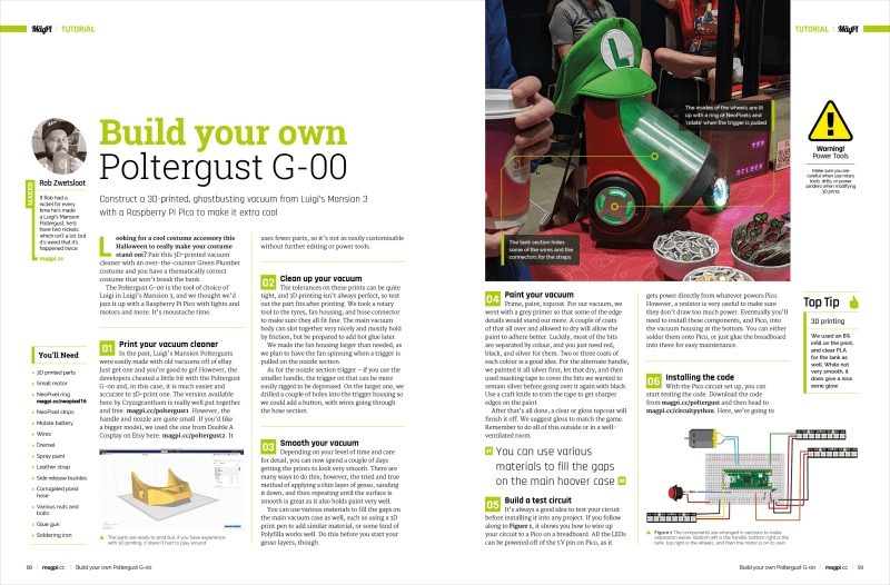
Reading Time: 2 minutesRetro Gaming with Raspberry Pi Pico & Pico W Our resident retro games expert KG Orphanides has crafted a superb feature for this month’s edition of The MagPi magazine. Discover how to emulate classic computers, hack 1980s hardware, and play retro games on a $6 microcontroller. Build a Mini Magic Mirror A…
-

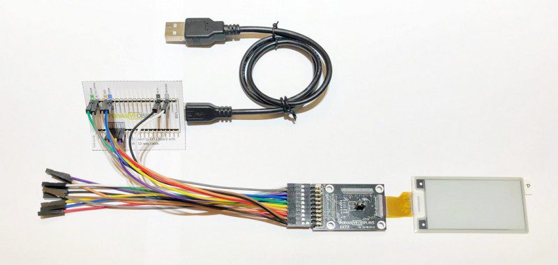
Win! 1 of 5 EPD Pico Kits
Reading Time: < 1 minuteSave 35% off the cover price with a subscription to The MagPi magazine. UK subscribers get three issues for just £10 and a FREE Raspberry Pi Pico W, then pay £30 every six issues. You’ll save money and get a regular supply of in-depth reviews, features, guides and other Raspberry Pi…
-

LEGO Reaction Wheel Inverted Pendulum
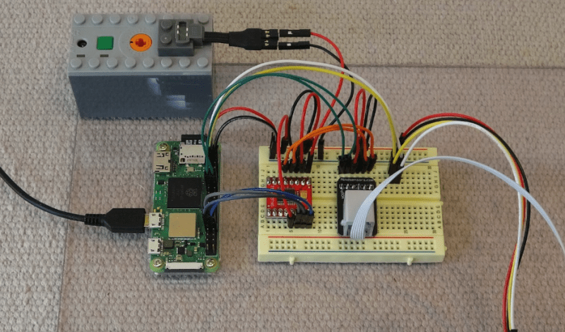
Reading Time: 3 minutesWell, that’s the theory, but in practice it’s not quite so easy and, as shown in his YouTube video, Juha had to alter his Python code repeatedly and make hardware adjustments to get the system to work to his satisfaction. Precision control A gyroscope and accelerometer on a mini IMU (inertia measurement…
-

LEGO Reaction Wheel Inverted Pendulum
Reading Time: 3 minutesWell, that’s the theory, but in practice it’s not quite so easy and, as shown in his YouTube video, Juha had to alter his Python code repeatedly and make hardware adjustments to get the system to work to his satisfaction. Precision control A gyroscope and accelerometer on a mini IMU (inertia measurement…
-

LED sphere
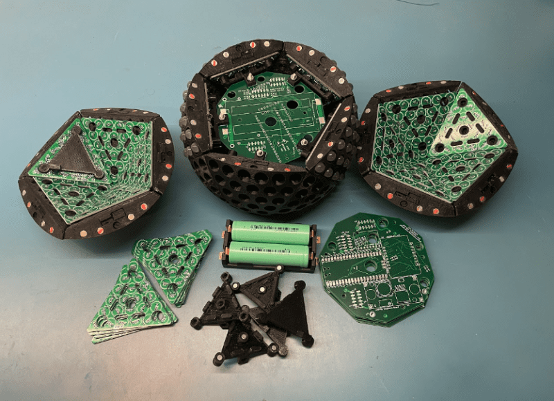
Reading Time: 3 minutesThe idea for the project followed a friendly chat. “I was having a lunchtime discussion at work with my friend, Jens, a 3D printing wizard, about doing things with LEDs that hasn’t really been done before,” Tom recalls. After ordering a 3D printer – “and wanting to use it for something more…