Schlagwort: robots
-

MiuraKit simplifies pneumatic robot design
Reading Time: 2 minutesSoft robotics is a challenging field, because it comes with all of the difficulties associated with conventional robotics and adds in the complexity of designing non-rigid bodies. That isn’t a trivial thing, as most CAD software doesn’t have the ability to simulate the flexibility of the material. You also have to understand how the…
-

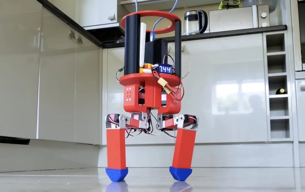
Can tripedal robots actually walk?
Reading Time: 2 minutesBuilding walking robots is difficult, because they either need a lot of legs or some ability to balance through their gait. There is a reason that the robots designed by companies like Boston Dynamics are so impressive. But lots of hobbyists have made bipedal and quadrupedal robots, while largely ignoring tripedal robots.…
-

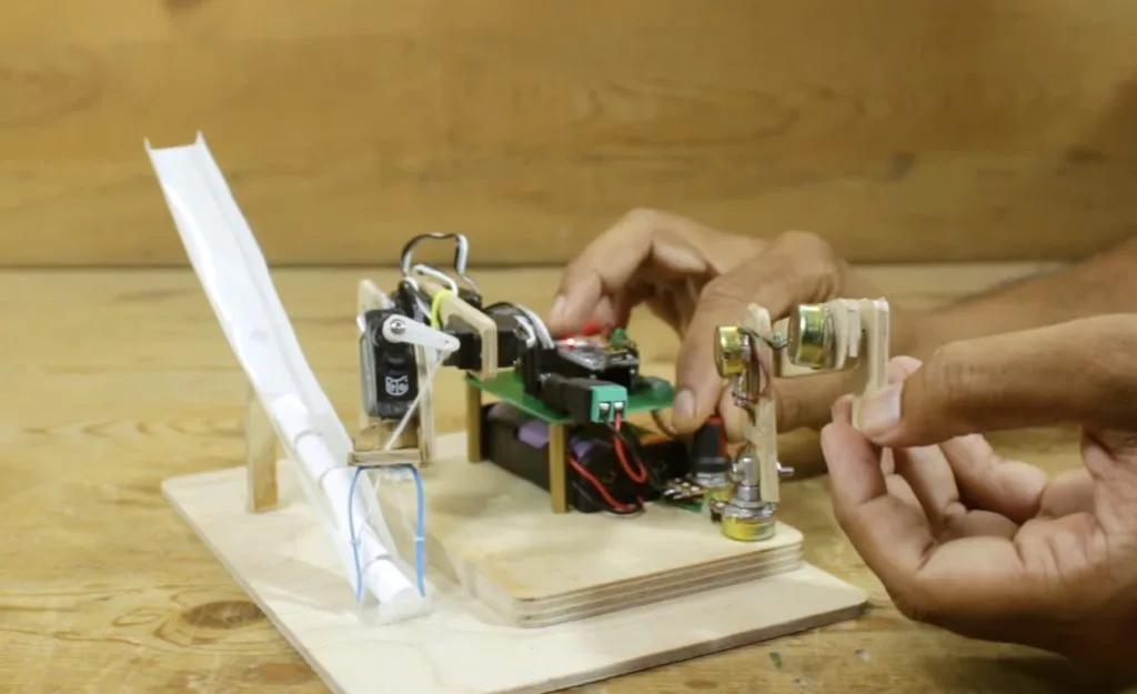
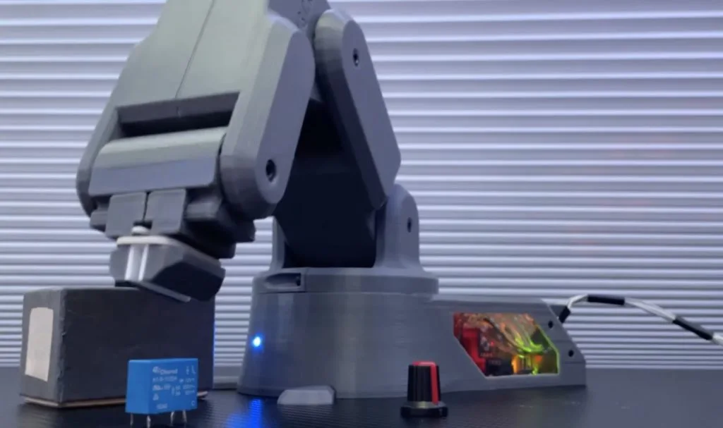
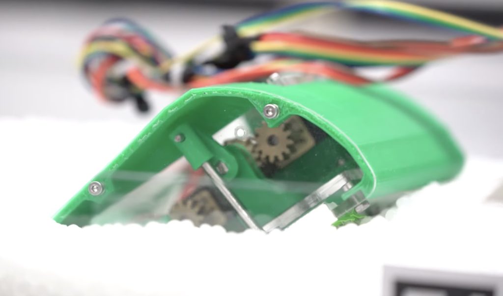
This cheap robot arm can follow recorded movements
Reading Time: 2 minutesThere are many ways to control a robot arm, with the simplest being a sequential list of rotation commands for the motors. But that method is very inefficient when the robot needs to do anything complex in the real world. A more streamlined technique lets the user move the arm as necessary,…
-

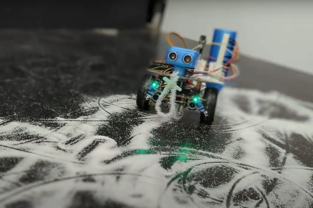
The Whimsy Artist is a little robot that both creates and destroys art
Reading Time: 2 minutesMany people find the subjectivity of art to be frustrating, but that subjectivity is what makes art interesting. Banksy’s self-shredding art piece is a great example of this. The original painting sold at auction for $1.4 million—and then it shredded itself in front of everyone. That increased its value and the now-shredded…
-

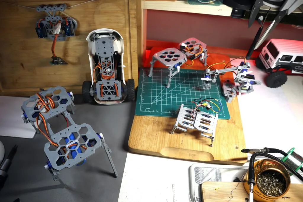
Bolt Bots are perfect for aspiring roboticists
Reading Time: 2 minutesWhile it is easier now than ever before, getting into robotics is still daunting. In the past, aspiring roboticists were limited by budget and inaccessible technology. But today the challenge is an overwhelming abundance of different options. It is hard to know where to start, which is why Saul designed a set…
-

An Arduino Leonardo-powered, 3D-printed robotic arm designed from scratch
Reading Time: 2 minutesGetting started in the world of robotics can be a very challenging task, even for more experienced hobbyists, due to how difficult it can be to achieve smooth and precise motion through programming. Frustrated by the lack of accessible options, the YouTuber known as “Build Some Stuff” decided to not only design his own, but…
-

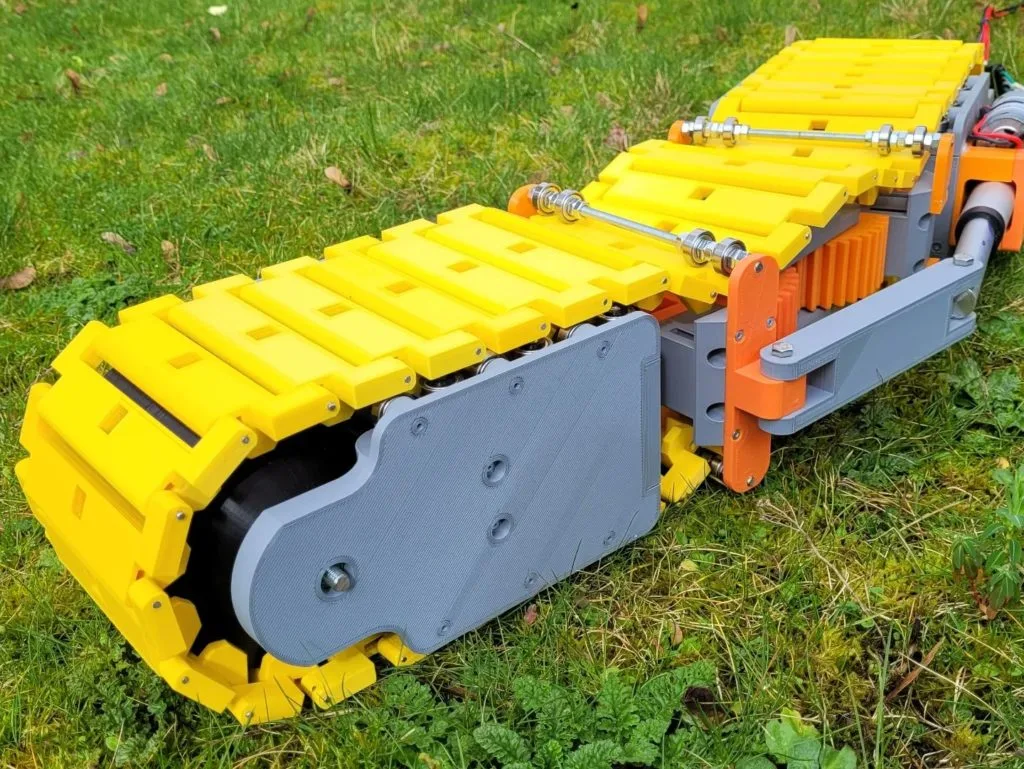
Bendy robotic tank steers by flexing
Reading Time: 2 minutesJames Bruton has become something of a YouTube sensation by experimenting with unusual drive mechanisms for his robots. While he does do other things, most of his projects seem to focus on designing, building, and evaluating drive types that are far outside of the norm. His newest project is no different. It…
-

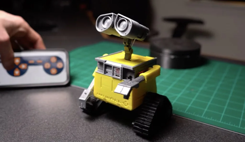
Mini WALL-E robot delivers gifts
Reading Time: 2 minutesWhile brainstorming gift ideas, Professor Boots settled upon creating a tiny present-delivering robot that could move around on its own power. Because WALL-E’s design already has a built-in compartment and is quite memorable, it became the jumping off point for the project. The entire robot is 3D-printed from a combination of rigid PLA for the…
-

The weird and wonderful history of chess-playing robots
Reading Time: 4 minutesWho said robots had to be all work and no play? For many years, people have been designing and building robots not just to help with chores, but to help us win games. Possibly the most famous examples of this are the robots that play chess. In this article, we’ll take a…
-

Celebrate good grades with this Arduino-powered robot
Reading Time: 2 minutesFor some students, getting decent grades or even finding the motivation to attempt to do schoolwork is a challenge, and this is often met with incentives such as money, praise, or simply avoiding embarrassment. Adam Soileau of element14 Presents had the idea to build a robot, which is an incentive unto itself by…
-

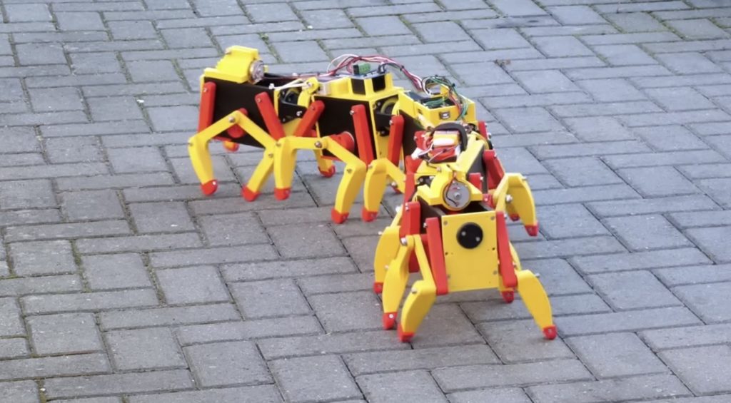
James Bruton’s robot centipede of many legs
Reading Time: 2 minutesStrangely, no centipede has exactly 100 legs. They can have either more or fewer than 100 legs, but not exactly 100 because they always have an odd number of pairs. Sadly, that means that James Bruton’s centipede robot is anatomically incorrect — though cool nonetheless. Bruton built this centipede robot as a scaled-down prototype,…
-

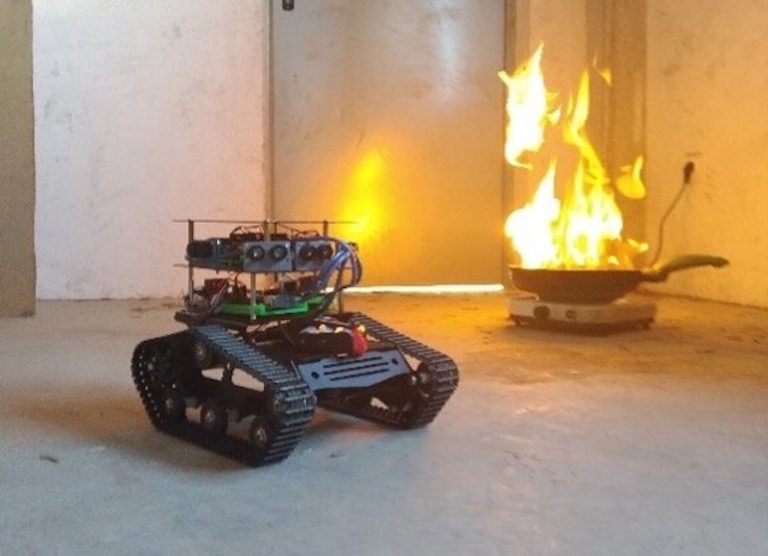
This little robot helps fight fires
Reading Time: 2 minutesFirefighting is a dangerous profession, but it is possible to mitigate some of that danger with good data. When firefighters entered a burning building, their biggest fear is the unknown. They don’t know if they can trust the structural integrity of the building, if there is a pocket of toxic or explosive…
-

This 3D-printed robot is made for sumo battle tournaments
Reading Time: 2 minutesWhile the majority of makers are unable to afford the fancy equipment and components that go into modern state-of-the-art battle robots, there do exist lesser-known tournaments for more DIY designs, including sumo robot battles. Instructables user noclaf8810373’s design incorporates all of the high-powered components one would expect to find, along with an innovative defense mechanism. Construction…
-
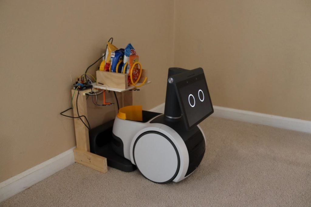
Snacky, the snack dispenser, enables snack delivery
Reading Time: 2 minutesSometimes you get a hankering for a snack, but there is no snack within arm’s reach. Such a situation is a tragedy and exactly what we built society and technology to avoid. To prevent this frankly appalling possibility, Michael Rigsby made Snacky, which is a snack-dispensing system that lets Amazon Astro robots…
-

Robot collects ping pong balls after matches
Reading Time: 2 minutesIf you frequent driving ranges, you’ve probably seen a machine (often attached to the front of an armored golf cart) designed to pick up golf balls. Because a driving range can easily fill up with thousands of golf balls an hour, such machines are necessary. After noticing that nobody wanted to pick…
-
This search and rescue robot creates 3D maps of disaster areas
Reading Time: 2 minutesIf you look at footage from the search and rescue efforts following any disaster, you’ll see that first responders have a very difficult time navigating through rubble to find people in need of emergency care. They also have to take extra precautions, as gas line ruptures and other hazards present dangers they…
-

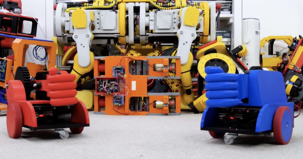
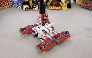
Roving Rock ‘Em Sock ‘Em Robots make the perfect Secret Santa gift
Reading Time: 2 minutesAs part of what has become an annual holiday tradition, several YouTube makers coordinated their efforts this year for a Secret Santa exchange. Returning participant James Bruton drew Emily the Engineer and found inspiration for his gift from an automatic boxing glove that she built. Taking that idea and running with it,…
-
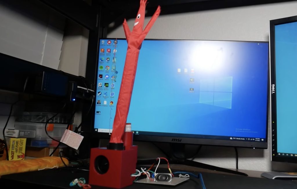
The Infineon team’s XXL Chatbot offers you yuletide greetings
Reading Time: 2 minutesInfineon is one of the world’s largest semiconductor manufacturers, but the company is made up of regular people like any other. Many of those people just happen to be engineers and they like to build gadgets and gizmos like the rest of us. Following a water cooler discussion about who had the…
-

Mole crab robot burrows into sand using flexible legs
Reading Time: 2 minutesRevolutionary new technologies tend to require small, incremental developments. For example, physicist Julius Edgar Lilienfeld filed a patent for a transistor way back in 1925. But it wasn’t possible to actually build transistors until semiconductor production caught up in 1947 — something that took decades of “boring” materials research. Such research may…
-

This Andor-inspired droid moves like the real B2EMO
Reading Time: 2 minutesThe new Andor TV show, set in the Star Wars universe prior to the events of Rogue One, is already a hit and a big part of that is thanks to the B2EMO droid. Like many of the other droids in the Star Wars franchise, B2EMO manages to be very expressive despite being cold, hard steel. It conveys emotions…
-

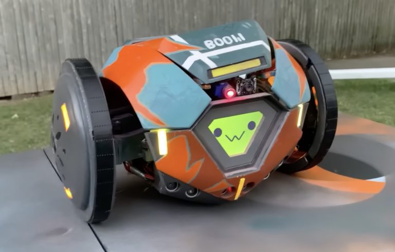
This Valorant fan made his own functional Boom Bot replica
Reading Time: 2 minutesValorant is a free-to-play 5v5 first-person shooter game. As in most shooters, players want to avoid getting shot. One way they can prevent incoming fire is to use Boom Bot, which is a little robot that will drive forward and chase enemies before exploding — while the player stays safely hidden out of…
-

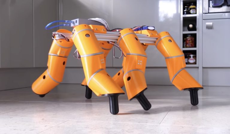
James Burton is giving legs their snakes back
Reading Time: 2 minutesJames Bruton gave that title to his most recent video as a good-natured jab at Allen Pan’s project about “giving snakes there legs back.” In Pan’s video, he built a robotic exoskeleton to let snakes walk around on motorized legs. But as Bruton noted in his video intro, those legs didn’t look…