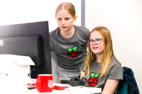
Schlagwort: robotics

  • Real Robot One is a high-performance robotic arm that you can build yourself

    Real Robot One is a high-performance robotic arm that you can build yourself

    Reading Time: 2 minutes

    Arduino TeamAugust 15th, 2022

    Robotic arms are versatile machines and are great for learning about principles of robotics or even doing useful work for hobbyists. That work might be picking and placing components on PCBs, packing boxes, or anything else you can imagine. But to perform that work well, the robotic arm needs more hardware than we tend to see in DIY projects. Pavel Surynek wanted a high-performance robotic arm and the result is RR1: Real Robot One, which features closed-loop feedback for accuracy and repeatability.

    In an open-loop robotic system, the controller only outputs positioning commands and doesn’t receive any feedback. Because it has no feedback, the controller doesn’t know if the position is accurate and can’t actively compensate for issues like backlash in the motors. Closed-loop feedback provides real-time, real-world position data to the controller, so it can ensure that results match commands. RR1 receives closed-loop feedback data from encoders on each of the six joints, which are driven by stepper motors through 3D-printed planetary gearboxes.

    An Arduino Due board controls the stepper motors through driver boards and monitors the encoders. It passes the encoder data to a computer dubbed RB1: Real Box One and receives control commands in return. The demonstrated end effector is a standard gripper and the rest of the arm is a combination of 3D-printed parts and aluminum extrusion. The current version of RR1 has a maximum reach of 80cm and can lift around 2kg. That’s already impressive, but Surynek plans to improve on it with an upcoming revision. 

    [youtube https://www.youtube.com/watch?v=EfE1ga313Wc?feature=oembed&w=500&h=281]

    Website: LINK

  • This snake robot is large enough to ride upon

    This snake robot is large enough to ride upon

    Reading Time: 2 minutes

    Arduino TeamAugust 13th, 2022

    If a robot is rideable, is it still a robot or is it a vehicle? We would argue that if it rolls on standard automobile-style wheels or even tank tracks, it is a vehicle. But James Bruton’s eight-wheeled robot snake bike is quite clearly something else. This “vehicle” started as a small functional model that everyone would call a robot. Now Bruton has finished the full-size rideable snake robot and it is something to behold.

    The robot consists of four caterpillar-like segments, each with a pair of wheels. Two of the segments have driven wheels, while the other two segments have free wheels. Each segment is able to pivot relative to its neighbor and can also tilt up/down. There are two reasons for the tilt actuation. The first is to compensate for the rider’s weight in order to keep all of the wheels on the ground. The second reason is to handle bumps and uneven terrain, similar to a car’s suspension. The rider sits on a motorcycle seat mounted to the third segment (which is driven), so their weight is roughly centered.

    This unusual setup requires a total of ten motors: four Hoverboard-style hub motors, three steering motors, and three tilt motors. Coordinating the control of that many motors isn’t trivial, which is why Bruton used three Arduino Mega 2560 boards. Each Arduino sends signals through two stepper motor drivers to the steering and tilt motors. Two of the Arduinos control the hub motors through ESCs (electronic speed controllers). Power comes from several big LiPo battery packs and Bruton pilots the robot using the custom universal robot remote that he designed for projects like this.

    Riding the strange snake robot didn’t go quite as well as Bruton had hoped, as the odd steering geometry doesn’t allow for lean and that causes the rider to fall off in turns. But it is still really cool to see in action and we love experimental vehicles!  

    [youtube https://www.youtube.com/watch?v=mnn_Y12RH_8?feature=oembed&w=500&h=281]

    Website: LINK

  • Move this custom robotic arm through a touchscreen interface

    Move this custom robotic arm through a touchscreen interface

    Reading Time: 2 minutes

    Arduino TeamJuly 19th, 2022

    Normally, robotic arms are controlled by a GUI running on a host PC, or with some kind of analog system that maps human inputs to various degrees of rotation. However, Instructables user Maurizio Miscio was able to build a custom robotic arm that is completely self-contained — thanks to companion mobile app that resides on an old smartphone housed inside a control box.

    Miscio started his project by making 3D models of each piece, most of which were 3D-printed. These included the gripper, various joints that each give a single axis of rotation, and a large circular base that acts as a stable platform on which the arm can spin. He then set to work attaching five servo motors onto each rotational axis, along with a single SG90 micro servo motor for the gripper. These motors were connected to an Arduino Uno that also had an HC-05 Bluetooth® serial module for external communication.

    In order to operate the arm, Miscio developed a mobile app with the help of MIT App Inventor, which presents the user with a series of buttons that rotate a particular servo motor to the desired degree. The app even lets a series of motion be recorded and “played back” to the Uno over Bluetooth for repeated, accurate movements.

    You can read more about this project here on Instructables.

    Website: LINK

  • Meet Nikola, a camera-enabled smart companion robot

    Meet Nikola, a camera-enabled smart companion robot

    Reading Time: 2 minutes

    Arduino TeamJune 6th, 2022

    For this year’s Embedded Vision Summit, Hackster.io’s Alex Glow created a companion robot successor to her previous Archimedes bot called Nikola. This time, the goal was to embed a privacy-focused camera and microphone system as well as several other components that would increase its adorability.

    The vision system uses a Nicla Vision board to read a QR code within the current frame thanks to the OpenMV IDE and the code Glow wrote. After it detects a code containing the correct URL, it activates Nikola’s red LED to signify that it’s taking a photo and storing it automatically.

    Apart from the vision portion, Glow also included a pair of ears that move with the help of two micro servos controlled by a Gemma M0 board from Adafruit, which give it some extra character. And lastly, Nikola features an internal mount that holds a microphone for doing interviews, thus letting the bot itself get held near the interviewee. 

    Nikola is a great compact and fuzzy companion robot that can be used not just for events, but also for interviews and simply meeting people. You can see how Glow made the robot in more detail here on Hackster.io or by watching her video below!

    [youtube https://www.youtube.com/watch?v=E4bL_V7fydc?feature=oembed&w=500&h=281]

    Website: LINK

  • Mobiot is a system that lets anyone automate everyday objects

    Mobiot is a system that lets anyone automate everyday objects

    Reading Time: 2 minutes

    Arduino TeamMay 25th, 2022

    So many tasks within a house can be reduced to a series of somewhat simple movements that are repeated each time that task is done, thus making it a prime target for automation. To make this process far easier than the traditional one of designing a robot by hand, writing some code and doing thorough testing, a team of researchers from UCLA and Texas A&M has created the Mobiot toolkit, which aims to combine each of these steps into a very straightforward application that takes care of the heavy lifting automatically.

    A user begins the process by utilizing their phone to first scan the target object, such as a trashcan, and then moving around the environment to simulate what motions the robot would need to do. From here, a pair of machine learning models interpret these motions and come up with a path containing a series of movements, including lifting, rotating, and simply moving forward. Once the user is confident in the virtual result, they can tell the system to transform the path into downloadable 3D parts, a list of electronics, and code along with complete assembly instructions.

    By using Mobiot, anyone can now build a robot for their specific needs and have one ready-to-go in a short amount of time with minimal prior experience in robotics. For more details, be sure to read the team’s paper here and watch their CHI ’22 video below.

    [youtube https://www.youtube.com/watch?v=fmHpvYRcf4I?feature=oembed&w=500&h=281]

    Website: LINK

  • This MKR WAN 1300-powered rover was inspired by the orb-weaver spider

    This MKR WAN 1300-powered rover was inspired by the orb-weaver spider

    Reading Time: 2 minutes

    Arduino TeamApril 11th, 2022

    Orb-weaver spiders are often found in gardens and are famous for the intricate webs they spin to catch pre, and as the name implies, this web is in the shape of a circle. In keeping with the theme, element14 user Miloš Rašic had the idea to build a small rover taking inspiration from the orb-weaver spider and NASA’s latest robots in that it “casts” a net of sensor boxes within a circular area that each report data to a central receiver, and it would do so autonomously.

    For now, Rašic wanted to stick with measuring air quality, so he began by placing a MKR WAN 1300 into his first “sensor box” that would act as a transmitter to send the data to the receiver via LoRaWAN. From here, he included a DHT22 for temperature/humidity, a BMP280 for air pressure, a QYF-919 real-time clock module, and an HL-83 rain sensor. A pair of AA batteries provided power to everything.

    The receiver, or “ground control station,” consisted of another MKR WAN 1300 board, an LCD, a buzzer, and a battery level module. Apart from the sensor boxes, the rover proved to be the most challenging to implement, but at the end Rašic was able to get it working perfectly.

    To read more about the nature-inspired project, which was recently named the grand prize winner of element14’s Just Encase Design Challenge, check out his blog post here.

    Website: LINK

  • Can a triangle of tank tracks outperform omni wheels?

    Can a triangle of tank tracks outperform omni wheels?

    Reading Time: 2 minutes

    Arduino TeamMarch 16th, 2022

    Omni wheels are fantastic because they let a vehicle drive forward, backward, left, right, and rotate — all without a steering mechanism. There are only two catches: all four omni wheels must be driven and omni wheels don’t handle rough terrain or obstacles well. Tank tracks are perfect for rough terrain, so James Bruton thought to combine the two concepts. To test this idea, he built an Arduino-controlled robot with a triangle of tank tracks.

    This robot has three tank tracks, each of which is driven by a simple geared DC motor. Burton arranged those in a triangle formation, so each track is at a 60 degree angle to the other two tracks. Normally, an arrangement like this would be a disaster, as it couldn’t drive in any direction without dragging at least one of the tracks. But Bruton lined all of the tracks with small wheels, which have axes of rotation perpendicular to the track motor axles. Those wheels rotate freely, so the vehicle can move without resistance — even when that movement is perpendicular to one of the tracks.

    Movement requires the coordination of all three track motors in order to vector the motor speed. Bruton used an Arduino Mega 2560 board for the job, because it has plenty of pins available to control the motor drivers via PWM. It also had pins to spare for an SPI connection to an nRF24L01 radio transceiver, which receives commands from Bruton’s general purpose robot remote control.

    The robot drove quite well on smooth carpet and is able to maneuver in a manner similar to what you’d see with standard omni wheels. Unfortunately, it wasn’t able to handle obstacles. The tracks were too smooth to get traction on an obstacle and constructing them from a grippy material would have kept them from sliding when necessary. While the robot didn’t accomplish Bruton’s goal, it is still interesting to see in action and is a thoughtful exploration of alternative drive types. 

    Website: LINK

  • James Bruton’s strange bicycle robot self-balances with an omni wheel

    James Bruton’s strange bicycle robot self-balances with an omni wheel

    Reading Time: 2 minutes

    James Bruton’s strange bicycle robot self-balances with an omni wheel

    Arduino TeamFebruary 26th, 2022

    Omni wheels, sometimes referred to by the trademarked Mecanum name, are special wheels lined with rollers. Thanks to the orientation of the rollers, a vehicle equipped with four omni wheels (each driven independently) can move in any direction by vectoring each wheel relative to the others. A typical setup includes four omni wheels, but James Bruton proved that even a single one is useful when he built this strange self-balancing bicycle robot.

    This robot is part of a larger project exploring full-sized self-balancing bicycles. It’s a small robot meant for experimenting with some unusual concepts. The front wheel is an omni wheel with its own motor and an axle that is perpendicular to that of the rear wheel, which is a conventional wheel driven by a second motor. The orientation of the omni wheel means that the robot can move the front end left and right easily, providing the inverted pendulum dynamic for self-balancing. When the robot needs to drive forward or backward, the rear motor provides propulsion and the omni wheel rollers spin freely.

    As with other self-balancing robots, this requires fast and precise PID control to stay upright. An Arduino Mega 2560 board takes frequent readings from an IMU (inertial measurement unit) and detects if the robot tilts too far to one side. When it does, it turns the omni wheel motor in one direction or the other, measured by an encoder, to correct itself and balance. Commands sent from Bruton’s own custom remote tell the Arduino when it should rotate the rear drive motor. Steering commands influence the balancing routines, allowing the robot to lean or pivot in order to make a turn.

    Website: LINK

  • Adorable robots mimic Internet cookies

    Adorable robots mimic Internet cookies

    Reading Time: 2 minutes

    Arduino TeamFebruary 10th, 2022

    If you’re like most people, you click “accept all” whenever a website asks you to allow cookies. That button is big and enticing, begging you to click so you can get to your content without thinking about the purpose of the cookies. That purpose is usually to serve you personalized ads, but you let the website track you because it asked you in a nice way. To replicate that effect in a tangible way, Guillaume Slizewicz built these Arduino-controlled robots.

    “Accept All” is an art installation Nemur, Belgium’s Le Pavillon. It consists of a few small wheeled robots that drive around the room. When they see a person, they scurry over to bump into that person’s shins. And people are happy to let them, because the robots are very cute. One has silly little horns. Another wears a grass hula skirt. Another looks like a jelly fish going through a goth phase. As with Internet cookies, people comply with the robots’ minor annoyance because they are pleasant.

    But, like cookies, these robots are tracking people. A Google Coral AI board peers at the world through a small camera and detects people by using an OpenCV script. When a robot sees someone, its Coral board sends a command to an Arduino via serial. The Arduino then controls drive motors that push the robot into the person’s legs. Slizewicz doesn’t actually collect data on the people his robots encounter. But the point is that he could and nobody would mind, since the robots are endearing.

    (Image credits: courtesy Guillaume Slizewicz)

    Website: LINK

  • ElectroVoxel robots reconfigure themselves using magnets

    ElectroVoxel robots reconfigure themselves using magnets

    Reading Time: 2 minutes

    Arduino TeamFebruary 8th, 2022

    The ability to control magnetism is very powerful and acts as the basis for huge swaths of modern technology. Without electromagnetism, we likely would never have progressed into the digital age — we wouldn’t even have electric motors. Now engineers from MIT CSAIL are using electromagnetism for something new: reconfigurable robots.

    ElectroVoxel robots are cube-shaped modules that can self-assemble into more complex shapes. Each robot has electromagnet coils lining its edges. An Arduino Nano with a wireless transceiver drives those electromagnets, allowing for untethered operation. Power comes from LiPo batteries and the frames are 3D-printed. By controlling the current and polarity of each electromagnet, the robots can cling to each other. They can also move by using an attractive edge connection for a pivot point and repulsion for actuation. They can use that movement for basic locomotion or to reconfigure into new shapes.

    Unfortunately, ElectroVoxel robots only work in microgravity. Earth’s gravity is too strong for their electromagnetic repulsion to overcome for a pivot motion. For that reason, the engineers were forced to test the ElectroVoxel robots in “vomit comet” parabolic plane flight, which creates a microgravity effect. In that environment, the robots successfully reconfigured themselves into a variety of shapes without any external manipulation.

    Website: LINK

  • See how Nikodem Bartnik integrated LIDAR room mapping into his DIY robotics platform

    See how Nikodem Bartnik integrated LIDAR room mapping into his DIY robotics platform

    Reading Time: 2 minutes

    Arduino TeamJanuary 31st, 2022

    As part of his ongoing autonomous robot project, YouTuber Nikodem Bartnik wanted to add LIDAR mapping/navigation functionality so that his device could see the world in much greater resolution and actively avoid obstacles. In short, LIDAR works by sending out short pulses of invisible light and measuring how much time it takes for the beam to reflect off an object and return to its detector. By combining this distance value with the angle of the sensor at the moment of measurement, a virtual cloud of points can be built and used to represent the entire space around the robot.

    The LIDAR module Bartnik opted to use was fairly simple, as it sent measurements in frames over UART that encoded everything including the sensor’s angle, the distance, and the speed of the device. He then created a simple sketch for the MKR WiFi 1010 that takes advantage of the increased power and connectivity to read values and send them to a host machine for further processing and visualization. 

    The resulting Python script opens a websocket, which receives the aforementioned data, does some basic filtering, and then displays it within a point-cloud. It also determines the direction in which the robot should move and sends that command back to the MKR board so it can tell the attached Arduino Uno how to move the motors. 

    Website: LINK

  • Neatly fold your t-shirts with an Arduino-powered robot

    Neatly fold your t-shirts with an Arduino-powered robot

    Reading Time: 2 minutes

    Arduino TeamJanuary 3rd, 2022

    Folding t-shirts isn’t a fun process for many people, and even worse, it’s difficult to get them looking the exact same way when the pile of folded clothing is completed. So in order to make it easier, mechanical engineering students Pietro Oppici, Corentin Vandebroek, Stefano Pontoglio, and Quentin Bertieaux set out to build a robot of their own that could quickly and precisely fold shirts to perfection and drop them below. They also wanted it to be able to detect what kind of tee was present so the robot could adjust its folding style to match. 

    After designing and fabricating a mechanism consisting of birch and MDF wooden panels held together with 3D-printed hinges, the team opted to use an Arduino Uno board as the brains of the operation. From there, they attached a series of NEMA17 stepper motors, three of which were high torque for fast folding, and a servo motor for the final fold. A set of five DRV8825 drivers were then connected to the Uno, which delivered current from the 12V power supply to the motors.

    The program for the t-shirt folding robot starts off by taking readings from two photoresistors in order to detect if a shirt is present and if it has long or short sleeves. For long sleeves, the outer panels fold first, and then the rest of the movements follow from there. At the very end, a trapdoor opens at the bottom so the now-folded shirt can slide onto a neat pile of clothing below. 

    To see this project in action, you can watch the students’ video below and read more about it here on Instructables.

    Website: LINK

  • This Samsung Ballie-inspired spherical robot gets around on a couple of wheels

    This Samsung Ballie-inspired spherical robot gets around on a couple of wheels

    Reading Time: 2 minutes

    Arduino TeamJanuary 3rd, 2022

    Back in early 2020, Samsung demonstrated their Ballie robot concept at CES, and although it never got off the ground, it inspired Derek Lieber to create his own version of a gyroscopically stabilized robot that moves with a pair of hemispherical “wheels” on each side.

    Lieber’s project, which he calls “Ballbot2”, is based around a single Arduino Mega connected to a set of two LM6234 drivers that take the incoming 5V PWM signals and boost them up to the 12V required by the motors. Speaking of motors, the ones for the Ballbot2 aren’t the typical geared DC or steppers, but rather gimbal motors that use copper coils surrounding a central magnet to turn it. Detecting the current orientation of the magnetic field is done by utilizing four Hall effect sensors to sense its position and then send it in a digitized format to the Arduino for further processing and feedback. He mounted an XBee module to a custom shield, along with the two driver ICs, before attaching it to the Mega. The XBee allows for the robot to be remotely operated with a secondary XBee module, which reads data from a joystick and transmits it wirelessly. 

    With the components chosen and code finished, Lieber then constructed a body out of 3D-printed PLA filament in the shape of a wide ring, several smaller rings, and two hemispheres that flank either side of the robot and act as wheels. From there, he stuffed the battery pack, a few lead weights, and the electronics into the central portion of the robot before attaching the two sides. 

    To see Lieber’s Ballbot2 project in action, you can view his demonstration video below and you can download the design files/code here in his blog post.

    Website: LINK

  • Nikodem Bartnik created a powerful robotic chassis using T-Motor AK series actuators and Arduino

    Nikodem Bartnik created a powerful robotic chassis using T-Motor AK series actuators and Arduino

    Reading Time: 2 minutes

    Arduino TeamDecember 28th, 2021

    After attempting to incorporate a few AK80-9 actuators from T-Motor into a robotic arm project, YouTuber Nikodem Bartnik was forced to pivot to a different kind of project: a universal robotic chassis/platform. By using these high-power and high-precision motors, his robot could be both fast and accurate while moving along the floor.

    Once a flat plate had been cut from a piece of plywood with the help of a CNC router, Bartnik mounted the two motors and attached a wheel to each one. To control the motors, he went with a single Arduino Uno and fabricated a custom PCB that routes CAN bus signals between the Uno and the two motors. Power was provided to everything via a pair of LiPo battery packs for a total of around 24 volts. 

    Currently, the robot is essentially an RC car that responds to commands that it receives from somewhere else. In Bartnik’s project, he used an additional Uno connected to a laptop over USB and an nRF24 radio transceiver module to wirelessly send data to the robot’s nRF24 module. He also made a Python script, which can be used to set the speed of the robot’s movements and takes arrow key presses that are then converted to directional movements. 

    You can watch Bartnik’s video below for more information or you can check out the his repo here for the project code and design files.

    Website: LINK

  • Meet RobBob, a 3D-printed robot head that works with an N64 controller

    Meet RobBob, a 3D-printed robot head that works with an N64 controller

    Reading Time: 2 minutes

    Arduino TeamNovember 23rd, 2021

    Inspired by a special two-axis mechanism that uses a pair of beveled gears to create panning and tilting motions, maker and YouTuber JBV Creative wanted to integrate it into a larger kinetic sculpture that could move electromechanically while also looking great at the same time. This led to the creation of RobBob, which is essentially a robot-shaped head that has been placed onto a pan/tilt system. 

    Initially, RobBob could only move with the help of a person turning a pair of opposing knobs — one for each axis. But after some minor additions, including mounts on each side for a single servo motor and adapters that allow servo horns to attach to the knobs, RobBob could now move on its own power. At first, JBV considered using a serial monitor to send rotation commands, although he eventually settled on an N64 joystick since it was a more natural choice for fluid motion. 

    After writing a small program, which takes in joystick data from the N64 controller and converts it into positional data for the servos, JBV loaded it onto an Arduino Uno. To see RobBob in action, check out JBV Creative’s demo/build video below or read more about the project on his website.

    Website: LINK

  • James Bruton built a robot that moves like an earthworm

    James Bruton built a robot that moves like an earthworm

    Reading Time: 2 minutes

    Arduino TeamNovember 10th, 2021

    Self-propelling robots come in a whole host of shapes, sizes, and capabilities, with some being able to fly while other can walk on just a couple or many legs. But YouTuber James Bruton wanted to innovate on this concept even further by designing and building a robot that mimics an earthworm through extending and contracting segments at certain times to slowly inch along the ground. This class of motion is called peristalsis, and it works by constricting a ring of muscles to propagate material, such as in the case of the digestive tract, or to move an entire body. 

    For Bruton’s first prototype, he went with four identical segments that each contain a single linear actuator which pushes or pulls within a scissor mechanism to move the segment. The actuators were then connected to an Arduino Uno that is responsible for sending pulses that dictate the extent of motion in a series. Although it worked at least somewhat, this initial design proved far too slow, thus leading to a redesign.

    In this next iteration, each segment houses a powerful servo motor at the end of a scissor mechanism that rotates to extend or contract the segment. This way, the worm can raise up, fall further away, and pull the rest of the body along, akin to an inchworm. 

    For more details on the project, you can watch Bruton’s video or check out his GitHub repository here.

    Website: LINK

  • The Raspberry Pi Build HAT and LEGO® components at our CoderDojo

    The Raspberry Pi Build HAT and LEGO® components at our CoderDojo

    Reading Time: 6 minutes

    As so many CoderDojos around the world, our office-based CoderDojo hadn’t been able to bring learners together in person since the start of the coronavirus pandemic. So we decided that our first time back in the Raspberry Pi Foundation headquarters should be something special. Having literally just launched the new Raspberry Pi Build HAT for programming LEGO® projects with Raspberry Pi computers, we wanted to celebrate our Dojo’s triumphant return to in-person session by offering a ‘LEGO bricks and Raspberry Pi’ activity!

    A robot buggy built by young people with LEGO bricks and the Raspberry Pi Build HAT.

    Back in person, with new ways to create with code

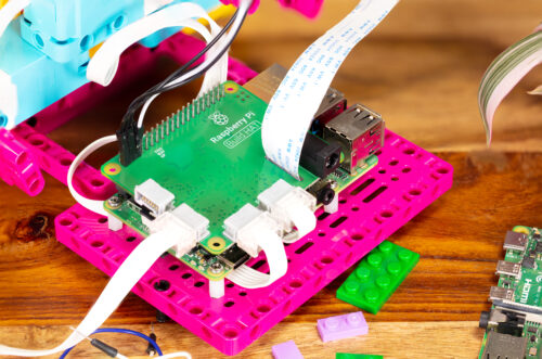
    The Raspberry Pi Build HAT allows learners to build and program projects with Raspberry Pi computers and LEGO® Technic™ motors and sensors from the LEGO® Education SPIKE™ Portfolio.

    A close-up of the Raspberry Pi Build HAT on a Maker Plate and connected to electronic components.

    What better way could there be to get the more experienced coders among our Dojo’s young people (Ninjas) properly excited to be back? We knew they were fond of building things with LEGO bricks, as so many young people are, so we were sure they would have great fun with this activity!

    Two girls work together on a coding project.

    For our beginners, we set up Raspberry Pi workstations and got them coding the projects on the Home island on our brand-new Code Club World platform, which they absolutely loved, so their jealousy was mitigated somewhat. 

    Being able to rely on your learners’ existing skills in making the physical build leaves you a lot more time to support them with what they’re actually here to learn: the coding and digital making skills.

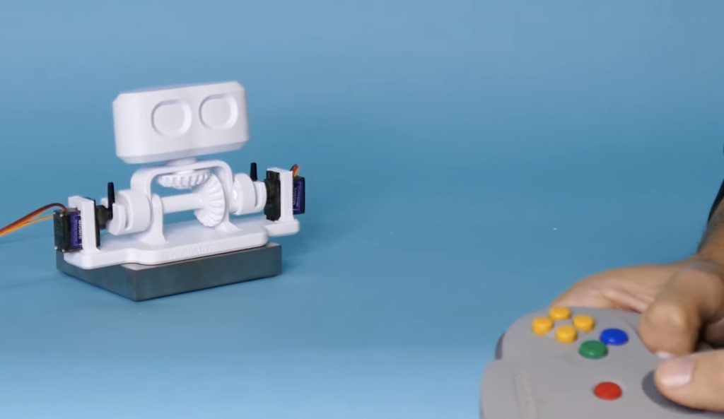
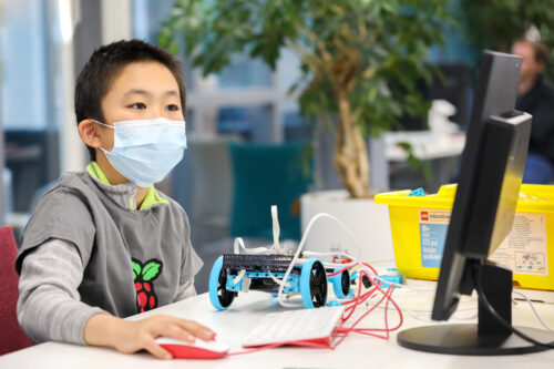
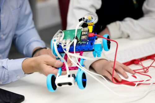
    We wanted to keep our first Dojo back small, so for the ‘LEGO bricks and Raspberry Pi’ activity, we set up just four workstations, each with a Raspberry Pi 4, with 4GB RAM and a Raspberry Pi Build HAT on top, and a LEGO Education SPIKE Prime set. We put eight participants into teams of two, and made sure that all of them brought a little experience with text-based coding, because we wanted them to be able to focus on making projects in their own style, rather than first learning the basics of coding in Python. Then we offered our Ninjas the choice of the first two projects in the Introduction to the Raspberry Pi Build HAT and LEGO path: make Pong game controllers, or make a remote-controlled robot buggy. As I had predicted, all the teams chose to make a robot buggy!

    ""

    Teamwork and design

    The teams of Ninjas were immediately off and making — in fact, they couldn’t wait to get the lids off the boxes of brightly coloured bricks and beams!

    Two young people work as a team at a CoderDojo coding club.

    Our project instructions focus primarily on supporting learners through coding and testing the mechanics of their creations, leaving the design and build totally up to them. This was evidenced by the variety of buggy designs we saw at the project showcase at the end of the two-hour Dojo session!

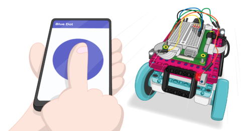
    One of the amazing things Raspberry Pi makes possible when you use it with the Raspberry Pi Build HAT and SPIKE™ Prime set: it’s simple to make the Raspberry Pi at the heart of the creation talk to a mobile device via Bluetooth, and off you go controlling what you’ve created via a phone or tablet.

    While beginner-friendly, the projects in the Introduction path involve a mix of coding, testing, designing, and building. So it required focus and solid teamwork for the Ninjas to finish their buggies in time for the project showcase. And this is where building with LEGO pieces was really helpful.

    Coding front and centre, thanks to the Raspberry Pi Build HAT

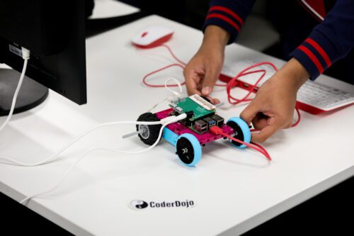
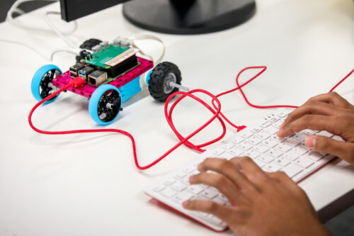
    Having LEGO bricks and the Build HAT available to create their Raspberry Pi–powered robot buggies made it easy for our Ninjas to focus on writing the code to get their buggies to work. They weren’t relying on crafting skills or duct tape and glue guns to make a chassis in the relatively short time they had, and the coding could be front and centre for them.

    The most exciting part for the Ninjas was that they were building remote-controlled robot buggies. This is one of the amazing things Raspberry Pi makes possible when you use it with the Build HAT and SPIKE™ Prime set: it’s simple to make the Raspberry Pi at the heart of the creation talk to a mobile device via Bluetooth, and off you go controlling what you’ve created via a phone or tablet.

    The LEGO Technic motors that are part of the LEGO Education SPIKE Prime set are of really high quality, and they’re super easy to program with the Build HAT and its Python library! You can change the motors’ speed by setting a single parameter in your code. You can also easily write code to set or read the motors’ exact angle (their absolute position). That allows you to finely control the motors’ movements, or to use them as sensors.

    Some of our teams, inspired by everything the SPIKE Prime set has to offer, tried out programming the set’s sensors, to switch their robot buggy on or help it avoid obstacles. Because we only had about 90 minutes of digital making, not all teams managed to finish adding the extra features they wanted — but next time for sure!

    A young person programs a robot buggy built with LEGO bricks and the Raspberry Pi Build HAT.

    With a little more time (or another Dojo session), it would have been possible for the Ninjas to make some very advanced remote-controlled buggies indeed, complete with headlights, brake lights, sensors, and sound.

    Learning with LEGO® elements and Raspberry Pi computers

    If you have access to LEGO Education SPIKE Prime sets for your learners, then the Raspberry Pi Build HAT is a great addition that allows them to build complex robotics projects with very simple code — but I think that’s not its main benefit.

    A robot buggy built by young people with LEGO bricks and the Raspberry Pi Build HAT.

    Because the Build HAT allows your learners to work with LEGO elements, you know that many of them already understand one aspect of the creation process: they’ve got experience of using LEGO bricks to solve a problem. In a coding or STEM club session, or in a classroom lesson, you can only give your learners limited amount of time to complete a project, or get their project prototype to a stable point. So being able to rely on your learners’ existing skills in making the physical build leaves you a lot more time to support them with what they’re actually here to learn: the coding and digital making skills.

    You and your young people next!

    The projects using the Raspberry Pi Build HATs were such a hit, we’ll be getting them and the LEGO Education SPIKE Prime sets out at every Dojo session from now on! We’re excited to see what young people around the world will be creating thanks to our new collaboration with LEGO Education.

    Have you used the Raspberry Pi Build HAT with your learners or young people at home yet? Share their stories and creations in the comments here, or on social media using #BuildHAT.

    Website: LINK

  • Duco is a wall-climbing robot that paints circuit murals

    Duco is a wall-climbing robot that paints circuit murals

    Reading Time: 2 minutes

    Arduino TeamOctober 6th, 2021

    When we think of circuits, we tend to picture wires or PCB traces. But a circuit is anything that conducts electricity between components. Today we have more options than ever before thanks to material like conductive ink and thread. Utilizing conductive ink on a large scale, Duco is an open source wall-climbing robot that brings interactivity to vertical everyday surfaces.

    Duco’s inspiration came from Sandy Noble’s fantastic Polargraph, which was a hanging pen plotter robot that could draw large images. But those images didn’t serve any purpose beyond visual appeal. Duco takes the Polargraph idea into a whole new direction. By swapping between special pens, Duco can draw conductive, dielectric, cleaning, or decorative lines on walls. Those combine to create multilayer functional circuits.

    An Arduino Uno board controls Duco through a motor shield. It has two stepper motors, a servo motor, a linear actuator, and a UV light. It is capable of switching between two different pens — normally the conductive and dielectric ink. The UV light cures the ink after Duco applies it to a wall. Most of Duco’s frame parts were 3D-printed.

    In one demonstration, Duco drew a working piano circuit onto a wall. Once the components, including control boards and speakers, were added to the circuit, people could play the piano by touching the conductive pads. In another demonstration, Duco turned a wall into a large capacitive touch sensor grid similar to a massive track pad. Duco’s creators even experimented with a laser module add-on, which let the robot cut the circuit “substrate” material.

    Website: LINK

  • OMNi is a modular, omnidirectional robot for museum duties

    OMNi is a modular, omnidirectional robot for museum duties

    Reading Time: 2 minutes

    Arduino TeamOctober 5th, 2021

    Museums allow people to explore topics in history, science, and much more through the use of exhibits that are often comprised of screens or some other interactive medium. Staff are given the role of visiting each one periodically and checking to see if they still work correctly as well as guide visitors around the area, thus taking them away from other tasks. To solve this problem, a pair from EDM Studio in Vancouver (Will Donaldson and Darran Edmundson) wanted to build an autonomous telepresence robot, called “OMNi,” which could do both on its own. 

    The system they came up with relies on a set of three omni wheels placed in a triangle formation around a circular base plate for creating precise movements. Positional feedback is gathered by measuring the motors’ RPM with a closed-loop PID controller/Arduino Nano combination and sending that information via I2C to a central Raspberry Pi 4. There is also a small LIDAR module on the robot that gathers point-cloud data and constructs a digital map for autonomous navigation and positioning. 

    The robot was designed with modularity and expandability in mind, which is why the top plate has an ample number of holes drilled into it for attaching certain accessories. One of these is a robotic gripper that utilizes servo motors to grab objects or touch a screen. 

    To read more about how OMNi was constructed and used in a museum setting, you can read the Donaldson and Edmundson’s writeup here on Hackaday.io.

    Website: LINK

  • Flingbot is a robot that flings paint at a canvas to create art

    Flingbot is a robot that flings paint at a canvas to create art

    Reading Time: 2 minutes

    Arduino TeamSeptember 20th, 2021

    Jackson Pollock was famous for his unique style of splattering large blobs of paint across a canvas, and it was this technique that JBV Creative was trying to imitate. But rather than working by hand to painstakingly dip a brush into paint and then flinging it many times over, he wanted to build a robot that could do this task for him while still creating art. 

    The main part of the Flingbot, the name JBV gave to his system, is comprised of a catapult arm that is capable of both rotating and adjusting how far it can throw paint. A servo motor at the back pulls an elastic band a certain amount based on the desired distance, and a second one releases a pin to perform the launching action. As another parameter for generating abstract art, the silicone scoop itself can bend to change its shape. Every servo motor is connected to a single SSC-32U servo controller board that receives commands from an Arduino Uno.

    Paint gets dispensed from one of the 12 total reservoirs that each has a gravity-feeder out its base with a servo motor that controls how much paint is deposited into the scoop. Once all of the paint has been collected for a launch, the Uno adjusts the angle and tension of the arm and finally releases the paint. 

    To see how JBV Creative constructed this robot and a glimpse of the wildly unpredictable artwork it produced, check out his video below as well as his project write-up here.

    [youtube https://www.youtube.com/watch?v=9XyE41_ANrc?feature=oembed&w=500&h=281]

    Website: LINK

  • Robotic waiter learning to serve drinks

    Robotic waiter learning to serve drinks

    Reading Time: 2 minutes

    The maker of this robotic waiter had almost all of the parts for this project just sat around collecting dust on a shelf. We’re delighted they decided to take the time to pick up the few extra bits they needed online, then take the extra hour (just an hour?!) to write a program in Python to get this robotic waiter up and running.

    It’s learning! Bartending is hard

    We are also thrilled to report (having spotted it in the reddit post we found this project on) that the maker had “so much fun picking up and sometimes crushing small things with this claw.” The line between serving drinks and wanting to crush things is thinner than you might imagine.

    And in even better news, all the code you need to recreate this build is on GitHub.

    Robo arm, HAT, and Raspberry Pi all together

    Parts list

    First successful straw-drop. Perfecto!

    reddit comments bantz

    One of our favourite things about finding Raspberry Pi-powered projects on reddit is the comments section. It’s (usually) the perfect mix of light adoration, constructive suggestions, and gateways to tangents we cannot ignore.

    Like this one recalling the Rick and Morty sketch in which a cute tiny robot realises their sole purpose is to pass butter:

    [youtube https://www.youtube.com/watch?v=X7HmltUWXgs?feature=oembed&w=500&h=281]

    No swears in this scene! But it is an adult cartoon in general

    And also this one pointing us to another robotic arm having a grand old time picking up a tiny ball, sending it down a tiny slide, and then doing it all over again. Because it’s important we know how to make our own fun:

    [youtube https://www.youtube.com/watch?v=qovZKW0DxWk?feature=oembed&w=500&h=281]

    We also greatly enjoyed the fact that the original maker couldn’t use the Rick and Morty “what is my purpose” line to share this project because they are such an uber fan that they already used it for a project they posted just the day before. This cute creation’s sole reason for existing is to hold an Apple pencil while looking fabulous. And we are HERE for it:

    Website: LINK