Schlagwort: raspi

  • Mini Bellagio Water Show

    Mini Bellagio Water Show

    Reading Time: 3 minutes

    Warning! Electricity & water: Take extra care when combining electricity and water in a project: the two should be kept well apart!

    Pump it up

    A pump pushes water from a reservoir (children’s paddling pool) through PVC piping attached to water solenoids connected to sprinkler tubing pointed up in the air. A Raspberry Pi controls the solenoids, creating the effect of water jetting out in sync with the music being played.

    “A total of eight solenoids were connected back to a mechanical relay, which in turn was controlled by Raspberry Pi,” says Nick. Seven out of the eight solenoids were connected to brass reducers to fit into garden sprinkler tubing. The eighth solenoid was a pressure control (relief) valve, which was used to control back pressure in the system.

    “When I wanted to ‘fire’ one of the seven solenoids to shoot water, Raspberry Pi would close the pressure solenoid,” explains Nick. This built up pressure in the PVC pipe, at which time Raspberry Pi would trigger a relay to open the desired solenoid so a jet of water would shoot out. “This was required to get any distance with very little water. I also didn’t want to burn out the pump, so the relief valve was open when no other solenoid was open.”

    Water is pumped from a children’s pool through PVC piping attached to water solenoids to turn the individual jets on and off

    Water music

    The music is synchronised to the solenoid firing by using FFT (fast Fourier transform) analysis performed on the audio in real-time. “I wrote a sequencer in Python to perform the analysis and determine which solenoids to turn on and off, based on a config file which maps high fidelity signals (bass, mid-range, etc.) to particular solenoids or solenoid groups,” says Nick. “In summary, you just put WAV files in a songs directory and start the Python code, which did all the heavy lifting in real-time.”

    One technical challenge was solving the timing discrepancy between the solenoid firing water and the musical note being heard by the audience. “The water had to be shot out of the jets approximately 600 ms ahead of the audio for the water to appear to be in sync with the music.”

    Another issue was safety, as mixing water and electricity can be hazardous. “The power for the system was a 12 V automotive battery,” reveals Nick, “so I used fuses to protect things, just as you would find in a family vehicle. I also tried to keep the dangerous gear out of reach of the general public.”

    Everything went well on the day, albeit with a few bugs: “There were certain sequences of musical notes where the FFT analysis would produce changes too rapidly for the back pressure and corresponding solenoid firing to produce much of a water jetting effect.” The result was a variance in water height from song to song.

    “I rode on the float during the parade, so the public reaction was the most rewarding part of the project for me,” he adds. “After people figured out what they were looking at, the responses ranged from laughter to astonishment. The public response made my day and all the efforts of the team worthwhile!”

    A waterproof fuse box is used to safely distribute power from a 12 V car battery

  • Win signed Raspberry Pi 4 computers, books, and accessories

    Win signed Raspberry Pi 4 computers, books, and accessories

    Reading Time: < 1 minute

    Subscribe

  • Build a Magic Mirror

    Build a Magic Mirror

    Reading Time: 5 minutes

    Magic mirrors have to be one of the most popular projects out there. Initially created by combining old laptops and semi-reflective observation glass, they appear as normal mirrors but with text and images that appear to float in mid-air. The information displayed is typically what you need as you’re preparing to leave the house: weather, news headlines, and transit information. Although they come across as advanced builds, the community behind the projects have made significant advances in making magic mirrors accessible to all. Let’s take a look at one of these makers and then have a go at building our own mirror.

    Creating a good magic mirror requires experience in many disciplines including carpentry, electronics, programming, and graphic design. Fortunately, the team at MagicMirror2, headed by Michael Teeuw (see The MagPi issue 54), have not only compiled tutorials and fostered a great community, they’ve also built their own open-source application. This modular system takes away all the programming and design pain. Best of all, you can expand the capabilities of your mirror through the hundreds of community plug-ins available and, if you wish, you can write your own. It’s no wonder it won the number one slot in our best projects feature for The MagPi issue 50.

    Assembling a simple magic mirror

    Would you like a magic mirror, but don’t fancy all that carpentry? Here’s a first project to ease you in without having to reach for the band-saw

    To build a magic mirror, you’ll need:

    Tip! Not for Raspberry Pi Zero

    A Raspberry Pi Zero would seem ideal for this project, but MagicMirror2 is incompatible with that model and the original Raspberry Pi 1.

    There have been some impressive magic mirror projects as makers around the globe challenge each other to improve on previous designs. Although the results are undoubtedly impressive, it can make the hobby look a little daunting to the beginner, especially if you don’t have access to the necessary equipment to build a custom frame. In this tutorial, we’ll assemble a simple magic mirror using off-the-shelf parts. This can be built in an afternoon and is a great way to find out whether you want to take it to the next step and get working on something a bit bigger.

    Prepare the frame

    To create our magic mirror, we will create a ‘sandwich’ of the frame, a piece of observation mirror acrylic, and the screen. It’s vital that all these are kept as clean as possible during assembly as any dust will get trapped and leave an irritating mark on your lovely mirror. Unpack the frame, remove the mount, and then remove the plastic clear sheet. You’ll need to carefully peel back the two protective layers and then replace the clear sheet in the frame. This is statically charged and will start to attract dust, so lots of cleaning is required. Return the mount to the frame.

    	The Ikea Ribba range is perfect for a starter project like this thanks to having unusually deep frames and a wide variety of sizes

    Mount the mirror

    The big ‘trick’ of a magic mirror is the use of two-way material, also known as ‘observation glass’. This material is the same that is used in police interview rooms and as privacy screening. It’s only semi-reflective, so the output from your screen can be seen ‘through’ the glass but it’s still effective as a mirror (if a little darker than a regular mirror). This material is cheapest when bought by the roll, so it’s ideal for custom-build or larger mirror projects. Ours is a £5 A5 acrylic sheet. Remove the protective sheeting and place in the frame, making sure it covers the open area. Secure with sticky tape.

    Add the screen

    We’re using the official 7-inch touchscreen for this project to make power requirements easier; we only need one cable to drive both Raspberry Pi and the display. It also happens to be a perfect size for this project. The touchscreen needs to be carefully placed so it’s in parallel with the frame and central. Secure with sticky tape.

    Secure in place

    The combined weight of a Raspberry Pi computer and the touchscreen doesn’t come to much, so rather than getting into complicated mounting solutions, we will apply generous amounts of gaffer (or duct) tape to hold everything in place. This is of course a very lo-fi solution – if you want to go for something more refined, you can consider making use of the mounting points on the screen that can be used with horizontal or vertical bars to attach to the inner edge of the frame. Check for any trapped dust or marks in our ‘sandwich’ before proceeding.

    The simplest way to mount the screen is to use gaffer or duct tape

    Just add Raspberry Pi

    Normally, you would mount a Raspberry Pi computer on top of the screen’s PCB on the provided standoffs. If you want to mount your completed mirror on the wall, this poses a problem, as the computer now sits quite a way proud of the frame. Your options are: 1) don’t care (not advisable), 2) buy a second frame and fix it to the original to double its depth, or 3) mount the Raspberry Pi computer on the side. We’ve gone with option three and it just fits, even with the supplied display cable. Make sure you line the back of the screen with insulation tape to avoid any electrical shorts and secure in place with a Velcro pad to allow for future access to the microSD card.

    Check and test

    With a microSD card with Raspbian installed, mount the Raspberry Pi 4 into place. Check the display ribbon cable hasn’t been stretched too much and the four jumper cables that connect the display to the GPIO are in the correct position. You should now be able to boot and see the Raspbian boot sequence through the display. It will probably look disappointingly dull. Don’t worry, we’ll address that in the next tutorial. If everything is free of dust, secured, and the display is working, shut everything down (you may need to connect a keyboard and mouse to do this).

    We’ve chosen gaffer tape, as the official screen is very light. This would be a terrible idea for a ‘full-size’ monitor.

    Professional magic mirror builds

    We’ve created a simple project for you here that requires no cutting or mains electricity. However, it would be remiss of us not to admire the work of those who have dedicated hours and hours to making the ultimate magic mirror. One of those is MagicMirror2 creator Michael Teeuw, who has created several mirrors completely from scratch, building his own frames and carefully mounting large monitors – all powered by Raspberry Pi computers, of course! The great thing about magic mirrors is you can start small and work up to masterpieces like this, learning as you go.

  • #MonthOfMaking, Starter Electronics and new entry-level Raspberry Pi 4 with 2GB RAM in The MagPi 91

    #MonthOfMaking, Starter Electronics and new entry-level Raspberry Pi 4 with 2GB RAM in The MagPi 91

    Reading Time: 2 minutes

    Click here to buy The MagPi Magazine issue #91

    #MonthOfMaking

    #MonthOfMaking

    Once a year The MagPi magazine readers come together and commit to build something. And we all reach out to each other online and offer encouragement. Pick up your copy of The MagPi magazine #91 to learn all about #MonthOfMaking.

    Let’s build together!

    Raspberry Pi 4 now comes with 2GB RAM minimum

    Raspberry Pi 4 with 2GB

    The entry-level Raspberry Pi 4 now comes with 2GB RAM and costs the same, just $35. This is a game-changer for Raspberry Pi, and its base computer now has the power to run as an effective desktop. We interview Eben Upton, Raspberry Pi founder and CEO, about the new introductory model and what it means for the world’s best single-board computer.

    Configuring your magic mirror

    Magic mirror modules and extensions

    Building a magic mirror is one of the most impressive starter projects around, and this month PJ Evans discovers how to configure your magic mirror with extensions. These are used to sprinkle all kinds of extra features onto a magic mirror.

    Project Showcase: Bellagio Fountain

    The best community projects

    You’ll find the best projects built using Raspberry Pi inside The MagPi magazine. One of the many stars this month is this Bellagio Water Show. It’s a truck-based reproduction of the classic Vegas water show, built and controlled using Raspberry Pi.

    Starter Electronics with Raspberry Pi

    Starter Electronics with Raspberry Pi 

    Electronics is the name of the game this month, and we’re not going to leave anybody behind. Hooking up circuits and components to Raspberry Pi (with those nifty GPIO pins) is how you get a computer to control things. And it all starts with a few simple electronic projects. We’ll show you how to use GPIO pins and pick up the right starter components, then Simon Monk walks us through some famous starter projects.

    Click here to buy The MagPi Magazine issue #91

  • Win a Raspberry Pi Desktop kit SIGNED by Eben Upton!

    Win a Raspberry Pi Desktop kit SIGNED by Eben Upton!

    Reading Time: < 1 minute

    Subscribe

  • WeatherMan

    WeatherMan

    Reading Time: 3 minutes

    Martin became enamoured of all things Raspberry Pi-flavoured in 2014. Looking for a one-box alternative to a PC for converted gadgets, he was tipped off by a reader that Raspberry Pi might work. He duly made a Raspberry Pi-powered VCR and Alexa Rotary Phone. Numerous ‘fruitful’ projects followed. There’s now a sizeable archive on Martin’s website.

    Discovering he enjoyed documenting projects as much as building them, he began specialising in giving new purpose to broken old tech – “especially items I remember being ‘the latest thing’ during the 1970s and 1980s when I was a child.”

    Helpfully, a Raspberry Pi Unicorn HAT is precisely the same size as the cassette player’s display window

    Weatherman: Walkman for weather

    Martin’s chance to ‘rescue’ one came when his mother-in-law sent him a broken old Hitachi player that she found during a clear-out.

    “I immediately fell in love with it,” Martin recalls. “It had a great retro look that drew me in”. On closer examination he realised the window in the cassette player’s door was – to the millimetre – the same size as a Raspberry Pi HAT. “At that point, all my other projects hit the back burner,” he says.

    “I’d been looking for a small case to hold a weather display for my desk for a while, and this was the perfect thing. I also had an unused Unicorn HAT HD lying around and this seemed like the ideal project for it.” To this he added servos and an awful lot of Sugru – a sort of malleable glue.

    “In the past I’ve used Lego and Meccano to put things together, but with space being so tight in the case, I used Sugru this time around. It’s very workable but sets hard like plastic, perfect for fixing components in the right place.”

    The WeatherMan currently relies on API data from the Dark Sky weather service, but Martin eventually hopes to link it up to a Raspberry Pi weather station. “With a Raspberry Pi at each end, it should hopefully be straightforward!” he says optimistically.

    The early 1980s-style ambient IoT weather display has a current conditions animation

    Getting the details right

    The main aim for what became the WeatherMan project was to keep the exterior as true as possible to the original. He wanted it to look like an ornamental piece sitting on his desk speaker, hiding a useful IoT (Internet of Things) device until it bursts into life.

    Martin thought the tape player seemed a bit naked without the iconic eighties headphones, so he looked for ways to incorporate them into the build. He drilled out the original jack plug and fittings and joined them together using a 2mm threaded rod. With a small nut on each end of the rod and a servo connector at the bottom, the headphones now respond whenever the weather is about to change. Their servo-controlled jiggling always makes Martin smile, even if it’s to alert him rain is on the way.

    Make your own WeatherMan

    Dismantle the cassette player to create as much space as you can inside. Retain any parts you want to reuse. You may need to trim down the case inside to make the components fit nicely.

    WeatherMan step 1

    You may need new bolts or a tiny magnet to make the cassette tape door close properly once you’ve tinkered inside. When you’re satisfied that it works well, hot-glue the cassette player case and door.

    WeatherMan step 2

    Use Raspbian Buster and adapted Python scripts to retrieve weather data from Dark Sky, display info on the Unicorn HAT, and (optionally) jiggle the headphones. Scripts and a ReadMe are on GitHub at magpi.cc/ghweatherman.

    WeatherMan step 3

  • Room Guard: build a Raspberry Pi motion sensor alarm

    Room Guard: build a Raspberry Pi motion sensor alarm

    Reading Time: 6 minutes

    Room Guard: You’ll Need

    Why an Automation HAT?

    Many Raspberry Pi physical computing projects directly use the GPIO to connect things like sensors, buzzers, and LEDs. In this case, we’re going use the incredibly versatile Pimoroni Automation HAT. This ‘input expander’ allows us to control devices that would normally either be incompatible or even damage your Raspberry Pi. As a small buzzer may not be particularly deterring to a would-be room invader, we’ve chosen a 120dB siren that requires more current that our Raspberry Pi can safely handle. So, we will give the siren its own power supply and safely control it using one of the Automation HAT’s relays.

    A close-up of the PIR sensor’s potentiometers. Carefully adjust with a small screwdriver as they can be fragile

    Prepare your Raspberry Pi

    It’s up to you what model of Raspberry Pi you use for this project. A Raspberry Pi Zero W is more than capable of running the code and we originally prototyped our guard using one. If you’re thinking of getting clever, though, such as adding facial recognition using a camera, you might want to go for the horsepower of a Raspberry Pi 4. Either way, start by attaching the Automation HAT carefully to the GPIO header, and secure with the provided standoff posts on the opposite side to ensure the HAT doesn’t wiggle about and come loose.

    Set up the software

    We’re going to use Raspbian Buster Lite as the operating system as there’s no need for a user interface, just a basic command-line operating system. That said, there’s no harm in installing the full version if you’re more comfortable with that. Download the image from the Raspberry Pi website and flash to a microSD card. Now, as ever, it’s time to log in and update everything with sudo apt update && sudo apt upgrade. Once finished, run sudo raspi-config and set up networking (if using WiFi). Now, install the Automation HAT software by running the following command:

    curl https://get.pimoroni.com/automationhat | bash
    

    This will guide through setting up for driver software and examples. You may need to reboot your Raspberry Pi afterwards.

    Get sensitive

    The PIR sensor has three connectors: one for 5V power in (which can be provided by the HAT), ground, and in the centre is the data line. Operation is very simple. If the sensor is triggered by movement, the data line goes ‘high’ (outputs current). After a period of no movement, it goes low (no current). Its sensitivity can be controlled by adjusting one of the potentiometers (the left one when it’s turned upside down – see Figure 1). The other potentiometer sets the minimum time for which the sensor reports movement. We could connect the PIR directly to the GPIO, but as the HAT is now in the way, we’ll use its inputs instead.

    Figure 1. The PIR sensor’s potentiometers (orange). Adjust carefully with a small screwdriver, as they can be fragile

    Connect the sensor

    Although this type of PIR sensor is widely available, they do vary in wiring. In particular, the orientation of Vcc (power in) and ground can be different. The sensor we’ve recommended here has both clearly marked on the PCB. Connect the ground pin to any of the GND connectors on the Automation HAT, then connect any 5V power output to the 5V in pin on the sensor. So that we know what state the sensor is in, connect the data line to any one of the buffered inputs on the HAT. Carefully check each of the screw terminals for a solid connection.

    Test the Room Guard Automation HAT

    When you installed the software for the Automation HAT, examples and documentation were included. We can use these to quickly test and calibrate the sensor. From the command line, run the following:

    python3 ~/Pimoroni/automationhat/examples/input.py
    

    You will now be shown the reading from all the input sensors. Watch the one to which you connected the data line in the previous step. It should report a 1 when it is activated (motion has been detected) and 0 when it ‘times out’. You can carefully adjust the two potentiometers on the sensor to fine-tune the sensitivity and timings to your preferences. Press CTRL+C to stop the Python script when you’re done.

    This project works well with Raspberry Pi Zero if you’re keeping it simple

    Warning! This might get loud

    The siren is capable of an ear-splitting 120dB. Always wear ear defenders in case you accidentally set the siren off. This particular model is tolerant of voltages less than 12V and the volume reduces accordingly. We recommend starting no higher than 5V, which is still incredibly loud. The siren requires its own power supply, so you’ll need to source one (we recommend something with variable voltages so you can experiment with noise levels). Before continuing, make sure you’re happy with the siren’s noise levels. If you don’t want a loud siren, there are many buzzers and quieter alarms available that will work to demonstrate the project and will be much safer for younger makers to handle.

    Relay race

    Relays are magnetic switches, allowing one device to control another without their circuits ‘touching’. The Automation HAT comes with three relays and we’ll use one to switch the siren on and off. Making sure it’s unplugged, snip the siren’s positive line (red wire) and strip a bit of wire on both ends. Now, connect the part going to the power supply to one of the relays on the terminal marked ‘COM’ (common). Connect the other part of the red wire to the same relay on ‘NO’ (normally open). Double-check everything and make sure the wires are secure.

    Set up the roomguard.py Software

    We can now read an input and create an output using the relay. Using your favourite editor, enter the roomguard.py code here. This is a simple loop that will check the sensor twice a second to see if movement has been registered. If so, the relay is switched into place, allowing current to flow to the siren and it sounds. Once the sensor no longer registers movement, the relay is deactivated and it all goes quiet. If you don’t fancy typing it in, you can download all this code and a few extras from GitHub.

    To run the code, enter the following on the command line:

    python3 roomguard.py
    

    Try moving about!

    Now Add notifications

    We now have a working motion-detection alarm, but this is meant to be internet-connected, so let’s make it smarter. It would be useful to have a notification sent to a smartphone when the alarm is activated. There are a many different types of notification service, and adding support for most is possible using just one Python library, Apprise. Have a look at the code for roomguard_notify.py on GitHub for an example of how to add notifications. Also, check out Apprise’s documentation.

    Adding alert notifications allows you to keep on eye on things when you’re away, and you can add images too

    Add a camera

    Now the basics are working, you can augment the alarm with additional sensors and/or notifications. The Automation HAT has plenty of remaining inputs and outputs for you to play with. A simple step would be to add a Raspberry Pi Camera Module. See if you can change the code to take a photo of the intruder and then forward that image to your notification. Look at the GitHub repository for an example.

    There’s plenty of scope for adding more to the project, such as an inexpensive keypad or a camera

    Make it your own

    What else could you add? One aspect of an alarm not implemented is any kind of deactivation. Could you add a web server so you can control the alarm from your phone? How about using a keypad to set an activation code? There’s potential to add batteries and additional PIR sensors to create a standalone unit. Use facial recognition software to identify who was in your room. There’s lots of avenues to explore. Over to you.

  • Audio radar – accessible radar tech

    Audio radar – accessible radar tech

    Reading Time: 2 minutes

    “The radar introduces the user in an easy and accessible way to electronics, [as well as] embedded systems and how radar detects return signals and performs filtering to measure radial velocity and distance to objects,” he explains.

    The radar is based on a Raspberry Pi 3B which hosts a web server to enter the parameters needed by the radar to operate. “The web server can be accessed by connecting to the ‘RadarPi’ WiFi and starts to broadcast upon power-up,” says Dewan. “It is also used to display the results obtained after the radar was operated.”

    What’s in a wavelength

    Normal radar uses radio waves (it was originally an acronym for RAdio Detection And Ranging); however, this version employs 8 to 12kHz of noise to measure distance – using the reflection time of the sound – and velocity, by making use of the Doppler effect. Parameters can be modified on a webpage generated by Raspberry Pi, allowing students to see how different settings change the results.

    Distance is calculated by measuring the time between the sound being emitted and then received after reflection

    “The radar proved to be a minor success in measurement of velocity, [although] with not the desired resolution and clarity due to the automatic gain of the microphone,” reveals Dewan. The automatic gain of the microphone automatically adjusts the received signals so that the signal never clips on the voltage range. When the velocity of a car is being measured, the microphone is overwhelmed by the road noise and the resulting plot is a quite faint line representing the velocity of the vehicle.

    “For distance measurement, the radar proved to be a major success,” he adds, “with the only downside being the resolution of the plot. When an object was measured at a set distance, the results would display the range ±10%. However, the known distance was always in the middle of the range and therefore a successful measurement. The reasons for the variation in distance was not investigated due to a time constraint, but initial tests proved that the automatic gain might be to blame.”

    Accessible radar

    A microphone listens for the reflected audio so calculations can be made

    Dewan’s system continues a long-running theme of projects involving radar, with this iteration trying to make it as open, affordable, and accessible as possible – which is why a Raspberry Pi was involved: “Raspberry Pi offered built-in wireless LAN and sufficient RAM capacity to host a web server,” says Dewan. “Other embedded systems, such as the STM32F04, were also considered, as a lot of previous work was done on this and the on-board analogue-to-digital (ADC) was also attractive. The STM and other Arduino-based systems had insufficient storage and RAM capacity, and therefore Raspberry Pi offered a superior solution.”

  • RetroFlag GPi Case

    RetroFlag GPi Case

    Reading Time: 2 minutes

    More than a simple enclosure for the Raspberry Pi Zero, this rather familiar-looking unit is a full-blown battery-powered gaming console that (just about) fits in the palm of your hand.

    The RetroFlag GPi Raspberry Pi Case is an ideal size and has a fab IPS screen

    Game on

    The clever design of the RetroFlag GPi case replicates that of eighties handheld consoles, including a cartridge-like unit that slides out of the rear and is quickly disassembled to reveal space for a Raspberry Pi Zero. A very neat ‘pogo’ mounting system means no header or soldering is required: a Raspberry Pi Zero just slots in and pressure maintains the contacts. The reassembled unit then slots into the main body and you’re ready to go. You can even access the microSD card without removing the ‘cartridge’. Power is supplied by three AA batteries or a supplied USB cable.

    A Raspberry Pi Zero or Zero W fits snugly inside the RetroFlag GPi Case

    Full and clear instructions are provided to install support for the gamepad buttons and also the on/off switch that provides easy and safe shutdown. We found the unit easy to assemble and had the retro games simulator RetroPie running in no time at all.

    We were particularly impressed by the RetroFlag’s screen, which uses IPS rather than TFT to give a razor-sharp display from any angle without any of the common side-lighting issues. A small audio speaker is built-in, with the option of headphones. The case itself is injection-moulded, solid and beautifully made.

    Specifications

    • Dimensions: 
138×81×32 mm

    • Weight: 
138 g

    • Display:
 2.8-inch IPS

    • Powered by:
 3 AA batteries or USB

    • Compatibility:
 Raspberry Pi Zero or Zero W (not Zero WH)

    Verdict

    Pi Hut’s RetroFlag GPi is one of the best gaming cases we’ve seen. A great design, easy assembly and, most of all, great fun to use. An essential 
purchase for any retro gamer.
    10/10

  • Pi Wars 2020 robots raring to go

    Pi Wars 2020 robots raring to go

    Reading Time: 2 minutes

    Pi Wars 2020 is going to be an absolute train wreck – at least that’s the hope of its organisers, Mike Horne and Tim Richardson. With a somewhat apocalyptic atmosphere swirling when it came time to choose a theme, Pi Wars organisers declared the 2020 event – the sixth Raspberry Pi robot battle weekend – would have a Disaster Zone theme.  

    Fans of zombie films, dystopia, and event horizons rubbed their hands in glee. The most switched-on 76 teams (of the 128 that applied) nabbed a place in the three-day competition which sees competitor Raspberry Pi-controlled robots pit their skills against each other in a range of non-destructive battles and challenges. Both autonomous and remote-controlled robots jostle for victory by completing up to seven fiendishly complex tasks. 

    Forest Fighters Shrub Bug robot at Pi Wars 2019. Photo by Mark Mellors (https://www.flickr.com/photos/7205519@N08/albums/72157679663827238)

    Catastrophic courses

    In previous years almost all the courses have been built by co-organiser Tim Richardson. This year sees several other course builders get in on the act, including Phil Hall with his Eco Disaster challenge [pictured]. Here, robots must navigate a course away from the toxic sludge spilled by an overturned tanker and reach the safe zone.

    Catastrophe and chaos will proliferate at this year’s Disaster Zone-themed Pi Wars. This is the new Eco Disaster course

    Robots vying for victory at Pi Wars 2020 will also have to face the ‚blind maze‘ of the Escape Route challenge and a bomb defusing Minesweeper course. Autonomous robots will encounter Lava Palava while robots that are remotely controlled face Zombie apocalypse, The Temple of Doom obstacle course and a Hindenburg Disaster version of the fiercely competitive Pi Noon balloon-popping head to head encounter.

    Rival robots circle each other in the Pi Noon ring at Pi Wars 2019

    DIY designs

    Newbies, veterans, and school teams each have dedicated competition days, helping ensure everyone has a fair shot of victory. Teams from 17 countries are taking part. Unlike TV’s Robot Wars (the original inspiration for Pi Wars), there’s no celebrity version – and each team is expected to design, build, and test their own robot.

    Pi Wars 2019 competitor Diddybot (photo by Mark Mellors) https://www.flickr.com/photos/7205519@N08/albums/72157679663827238

    Competitor entries to this year’s event, held over the final weekend of March at the University of Cambridge Computer Laboratory, filled up months ago and many teams have been blogging and tweeting about their robot’s build progress

    Spectator tickets are available here. Volunteers and under 16s get in free.

  • 50 Raspberry Pi 4 Tips and Tools: pt 2

    50 Raspberry Pi 4 Tips and Tools: pt 2

    Reading Time: 6 minutes

    For part I of this guide to tools every maker should have, see here.

    Warning

    Some of these tools use mains electricity and heated parts. Always follow connection instructions and never leave heated elements unattended.

    Cutting, trimming and coverings

    26. Card trimmer

    A card trimmer will enable you to cut crisp straight lines in paper or thin card. It’s much quicker than a ruler and craft knife. Small ones are good for trimming photos, and a good-quality trimmer will last for years.

    27. Robotic craft cutter

    A robotic craft cutter is very much like a plotter, but has a knife instead of a pen. They can cut very intricate designs out of paper and fairly thick card. They can be a bit temperamental and often need a sticky carrier sheet to work well.

    Equipped with a knife for precision cutting, a robotic craft cutter can cut intricate designs out of paper or card

    28. Laser cutter or engraver

    Laser cutters and engravers fire a laser at a material to either cut through it or to leave a mark or indent on the surface, depending on the intensity of the laser. Very effective for cutting irregular wooden shapes.

    29. Laminator

    Lamination is the process of coating a material with a plastic film. This protects the material from moisture and other damage. It also makes the material thicker. Plastic laminate comes in various thicknesses and surface finishes.

    Laminate your prototype model to protect it from moisture and general wear and tear

    30. Conductive paint

    Generally coloured black and supplied in a tube, conductive paint can be used to draw electrical circuits on paper or card, or to improve poor connections between components and even to create touch-sensitive areas on materials. Dries in a few minutes.

    Use conductive paint to draw electrical circuits or to improve connections between components

    31. Acrylic and thermoplastic sheet

    Acrylic plastic sheeting is very tough and can be cut using a saw or CNC router, whereas thermoplastic sheets are malleable when heated with a heat gun. Once cool again, thermoplastic retains its new shape.

    32. Polymorphic plastic

    This material is usually supplied as granules or beads. You can heat them up in boiling water and they will clump together in a mass. While still warm, you can mould the plastic before it sets hard in ten minutes or so.

    Polymorphic plastic beads can be moulded or shaped anyway you like and, once wet, will set hard in 10 minutes

    33. Aluminium foil

    Available from convenience stores and supermarkets, aluminium foil can be used as a conductor in a circuit, as shielding to reduce electromagnetic interference, and also to reflect light and heat either away from or towards an area.

    Tools for connecting electronics

    34. GPIO ruler/chart

    GPIO (general-purpose input/output) pins are the interface between your Raspberry Pi and electronic components. Until you learn which pin is which, you’ll need a guide. There are several GPIO rulers and guides available to make life easier.

    A GPIO ruler provides a handy reference guide to which coloured pin does what

    35. Header connector

    For some projects, you may want to connect a HAT or pHAT to your Raspberry Pi, but not place it right on top of the board. In this case, a female-to-male 40-way ribbon connector enables you to extend the reach of the GPIO pins.

    36. Jumper wires

    Jumper wires connect Raspberry Pi GPIO pins to electronic components. Use them with a breadboard to prototype your circuit, or solder them directly to components. Be sure to get a variety of different colours to make your project easier to understand.

    Jumper wires connect components on a breadboard or can be soldered directly to it

    Tools for soldering

    37. Desoldering kit

    This equipment enables you to clean melted solder from components on a printed circuit board, allowing their removal or replacement.

    If you're doing anything with electronics, a soldering kit is pretty much essential

    38. Soldering station

    A handy stand to place a soldering iron while it is still plugged in and hot. The sponge should be wet to clean the end of the iron.

    39. Soldering iron

    An absolute necessity for soldering or desoldering components onto printed circuit boards. For detailed work, an iron with a pointed end is best.

    40. Third hand tool

    Usually has a solid, heavy base with jointed arms with clips or holders at the end, and a magnifying glass for working on small components.

    41. Multimeter

    You need to be able to measure current, resistance, and voltage in your circuits. Digital multimeters can cost as little as £10.

    Measure voltage, resistance and current using a multimeter

    42. Gorilla Glue

    Similar to superglue, but supplied with a brush to apply it, Gorilla Glue sticks most materials and very good for 3D-printed parts. Usually takes around half an hour to dry.

    Ideal for sticking together 3D parts - or almost anything else - Gorilla Glue is easier to apply than superglue because it comes with an applicator brush

    43. Nuts, bolts & screws

    Having a good range of sizes and shapes of nuts, bolts, and screws is absolutely necessary for making anything that you are not going to glue. Keep a jar full of spares.

    We recommend you have an abundant supply of nuts, bolts and screws

    44. Sticky tape

    For temporarily holding things in place or insulating wires. You can also use tape for wrapping handles of tools. Also good for removing cat fur from jumpers.

    Sticky tape is great for quick fixes and adding grip to tool handles

    45. Blu Tack

    Usually used for keeping posters on walls, but can also be used for holding components in place while soldering. It also rubs out pencil marks if you don’t have an eraser.

    46. Power bank/batteries

    Most maker projects need power, so it is a good idea to have a range of battery holders. Power banks for recharging phones can also be used for 5V supplies.

    Many maker projects depend on a steady supply of batteries

    47. 3D creation software

    You may want to visualise your build before starting, and there are many 3D software packages to help you for free, like Blender; or with free trial versions, such as SketchUp.

    3D creation software such as Blender and SketchUp help you visualise and plan your project

    48. Fritzing

    When you have completed your project, you may want to document how you did it. Fritzing is a great program for laying out circuit diagrams.

    Use Fritzing to document your completed project

    49. Paper clips

    Can be used to connect components, clean out small nooks and crannies, or hold materials in place. Apparently, you can pick locks with them too!

    50. Documentation

    One of the most important tools you will use for just about any maker project is reference material. Your Raspberry Pi may have come with some tips and hints about making, and many kits have worksheets and Frequently Asked Questions sections with them.

    Also, make best use of the online resources that detail other people’s experiences: like Stack Overflow for information about any technical subject; blogs such as modmypi.com, recantha.co.uk, and blog.pimoroni.com; and of course the Raspberry Pi site and magazines. If you’re stuck getting something to work, it’s likely someone else has had the same problem!

    Get advice and how-to guides from invaluable online sites and component maker's blogs

  • Raspberry Pi Recovery Kit project showcase

    Raspberry Pi Recovery Kit project showcase

    Reading Time: 3 minutes

    Should the world ever be plunged into an apocalypse, then Jay Doscher should do just fine. He’s created a rugged-looking laptop using a Raspberry Pi 4 computer and placed it within a small, air- and watertight Pelican case. Aimed at getting technology up and running in the event of a disaster, it should see him through the most testing of times.

    “Most people prioritise food and shelter in the event of a disaster, but what do you do when those are resolved – how do you get technology working again?” asks Jay, an IT professional and technology enthusiast based in the San Diego area.

    “The apocalypse is more of a thought exercise for me, but I’ve certainly created a very useful computer that is much easier to work on or modify than a regular laptop.” Jay likes to focus on open-source projects, as his Twitter and Instagram feeds reveal.

    Jay Doscher is an IT professional and tech enthusiast to enjoys making open-source projects

    Past lessons

    Jay has been here before. In 2015, he popped a Raspberry Pi 2 into a weather-resistant enclosure and created the Raspberry Pi Field Unit that could run off a 12 V or higher power source, in this case a solar panel. Perfect for outdoor use, it also utilised an Adafruit real-time clock to retain accuracy when off the network. But it was far from perfect.

    “The Raspberry Pi Recovery Kit is an evolution of that previous build,” he says. “Although each has different goals, I wanted a Raspberry Pi setup that could be rugged and work in a more hostile environment. I also wanted a system that could serve more than one purpose, since the Raspberry Pi platform is so flexible.”

    One of the first issues he looked to address was the original lack of a keyboard. This time around, he bought a Plaid keyboard kit and, to his delight, noted that it was a perfect fit for his Pelican 1300 case. Jay also chose to use the official 7-inch Raspberry Pi touchscreen. This did away with the need for a mouse, while freeing up a much-needed USB port on Raspberry Pi 4.

    The Plaid ortholinear (grid layout) keyboard was a perfect fit for the Pelican 1300 ruggedised case

    With attention paid to tight wiring and realising that he could get away with powering the unit using 5 V, thereby reducing the need for 12 V circuitry, it wasn’t long before the project began coming together. “A Raspberry Pi computer is perfect for this project because it’s small, flexible on GPIO, and has great support for third-party add-ons like the GPIO breakout HAT I used,” Jay says.

    Future-proofing

    For a neat interior and to ensure all of the components could be easily held in place, internal parts were printed on a Prusa i3 MK3S 3D printer. For the host of connectors, a panel was produced with locking switches that could turn individual components on and off. These allowed control over Raspberry Pi 4, display, and Netgear five-port Ethernet network, saving power in a potential emergency. A switch also allows toggling between an internal and external battery.

    The Raspberry Pi Recovery Kit laptop is based around a Raspberry Pi 4 and has a Netgear network switch mounted on the rear of its 7in touschscreen

    “The internal battery has been the most difficult part, and I am still working on that,” Jay says. “There are no real considerations on the Raspberry Pi board itself for battery management, and Raspberry Pi 4 was pretty power-hungry when I built this kit.”

    Thankfully, coding proved easier. “It’s a regular Raspberry Pi laptop in many ways, but I am working on scripts to mirror my GitHub projects, Wikipedia and Raspbian APT libraries while following their guidelines on proper mirroring,” he reveals.

    The result is a cyberdeck that can work as a portable standalone network core if needed. “It’s a great system to keep air-gapped from the rest of the network when not in use,” Jay concludes. The battle for survival starts here.

    Quick facts

    • No holes were drilled into the Pelican case

    • The entire device is kept watertight

    • The main frame took 24 hours to 3D-print

    • It can be powered internally and externally

    • It’s stored in an electromagnetic pulse shielding box

  • Group test: Best Raspberry Pi 4 thermal cases tested and ranked

    Group test: Best Raspberry Pi 4 thermal cases tested and ranked

    Reading Time: 9 minutes

    Raspberry Pi 4 – like all the other members of the ever-growing Raspberry Pi family – is entirely usable as is, and plenty of people appreciate the aesthetic of a bare board on a desk.

    For those who don’t, there are a wealth of cases – both first- and third-party – available. You’ll find one, the Raspberry Pi 4 Stand, mounted on the cover of this magazine, while the others in this group test can be found at all major retailers.

    Each case here has been tested for aesthetics, complexity of assembly, and its performance in keeping Raspberry Pi 4 running cool.

    How we tested

    Each case was given a heavy synthetic workload to represent a worst-case scenario. This workload, which stresses both the central and graphics processors, runs for ten minutes followed by a five-minute cooldown period. Full details of the workload can be found in The MagPi issue 88.

    Raspberry Pi 4 Stand

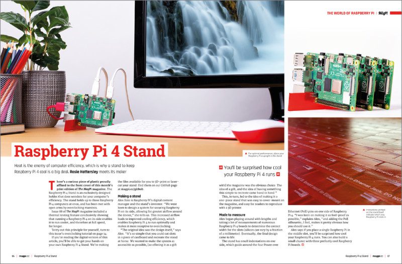
    Made by Pimoroni from a single piece of acrylic, the Raspberry Pi 4 Stand is as pure as it gets (and comes free with issue 90 of The MagPi magazine)

    Specifications

    • Dimensions: 120×20×2.8 mm

    • Material: acrylic

    • Weight (including one Raspberry Pi 4): 54 g

    • Number of boards supported: up to 3

    • Cooling method: vertical alignment

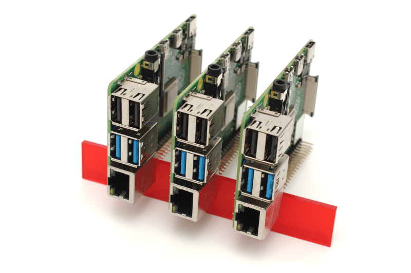
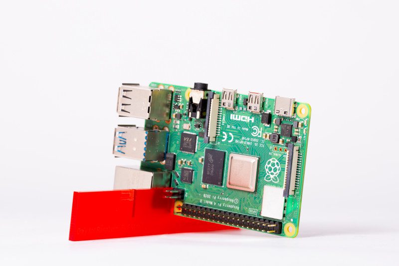
    The Raspberry Pi 4 Stand is about as simple as a case could possibly be. Laser-cut from a single piece of acrylic, there’s no complex assembly required: simply slot the stand between the Power over Ethernet (PoE) header and Ethernet port of Raspberry Pi 4 and pop it on your desk.

    The stand is designed to improve cooling by aligning Raspberry Pi 4 vertically, rather than flat on a desk. Previous thermal testing in issue 88 showed this is surprisingly effective, and the Raspberry Pi 4 Stand solves the stability issue which comes from balancing the board on its edge.

    There’s a bonus trick up the Raspberry Pi 4 Stand’s sleeve, too: it holds up to three Raspberry Pi 4 boards side-by-side, making a very cost-effective computing cluster. Whether you install one, two, or three boards, the Raspberry Pi 4 Stand is surprisingly stable and not unattractive – and it retains access to all ports and headers.

    The Raspberry Pi 4 Stand holds up to three boards side-by-side, making a very cost-effective cluster

    Thermal imaging

    The Raspberry Pi 4 Stand improves the bare performance, but Raspberry Pi 4 still gets hot under sustained synthetic load.

    The Raspberry Pi 4 Stand improves base performance but is less effective at dissipating heat under sustained synthetic load

    Thermal load

    Without additional cooling, the Raspberry Pi 4 Stand can’t prevent Raspberry Pi 4 from hitting its throttle point during testing.

    Verdict

    The Raspberry Pi 4 Stand is smart, free, and the only case on test to support more than a single board. Its cooling performance, though, is the weakest.

    Note: We don’t score our own products. [We think our Raspberry Pi 4 Stand is perfect – Ed.]

    Designed to blend in with home theatre products, the Flirc case is undeniably attractive

    Specifications

    • Dimensions: 93.7×66×26.5 mm

    • Material: aluminium

    • Weight (including one Raspberry Pi 4): 134 g

    • Number of boards supported: 1

    • Cooling method: passive heatsink (SoC only)

    • Extras: thermal transfer material pad

    Created as a means of drawing attention away from Raspberry Pi 4 when used as part of a home theatre installation, the £16/$16 Flirc combines a matte-finish silver aluminium housing with soft-touch black plastic to the top and underside. It’s an understated design, but one which does compromise efficacy: the plastic lid covers much of the surface area of the aluminium case, reducing its ability to bleed off heat.

    The case itself makes contact with Raspberry Pi 4’s system-on-chip (SoC) via a single hollow pillar and a bundled thermal interface material pad. Installation is simple, requiring only two protective sheets to be removed from the pad, and four screws to hold the case together.

    For those not interested in attractive home theatre setups, though, the Flirc comes with a major drawback: it offers no ready access to the GPIO, CSI, or DSI headers, though all external ports are easily reached.

    Flirc Raspberry Pi 4 Case is a good choice as part of a home theatre setup

    Thermal imaging

    The plastic lid prevents the Flirc from cooling entirely efficiently, while the hollow pillar can be seen as a cooler spot to the centre-left.

    Flirc's case cools Raspberry Pi 4 effectively but its efficiency is hampered by the plastic lid

    Thermal load

    Even with the lid in place, the Flirc case easily cools Raspberry Pi 4 during the synthetic workload run.

    Verdict

    Unless you need the GPIO, CSI, or DSI headers, the Flirc’s few design flaws are unlikely to matter: the case keeps Raspberry Pi 4 well clear of its thermal throttle point. 8/10

    Impressively feature-packed, the Argon One offers a lot for your money – including temperature-controlled active cooling

    Specifications

    • Dimensions: 105×95.6×35 mm

    • Material: aluminium

    • Weight (including one Raspberry Pi 4): 230 g

    • Number of boards supported: 1


    • Cooling method:
      passive heatsink (SoC, RAM), PWM fan

    • Extras: thermal transfer material pads, AV daughterboard, fan, labelled GPIO header with magnetic cover, smart power board

    The £19/$25 Argon One case packs a whole lot of functionality into a surprisingly small footprint. A daughterboard connects to Raspberry Pi 4’s AV and HDMI ports to re-route these to the rear of the case, alongside Ethernet and USB, while a second board pulls the GPIO header out to a colour-coded and silk-screen labelled header hidden under a magnetic cover on the top.

    The same board powers a fan, which is active when the temperature exceeds a user-configurable limit, and includes a smart power button which can safely turn Raspberry Pi 4 on and off with a press. There’s even space to route out CSI and DSI cables for a camera or display.

    Cooling performance is impressive. The Argon One prevented Raspberry Pi 4 from throttling without even needing to activate the fan – aided by the entire aluminium surface acting as a heatsink for the SoC and RAM chips.

    Argon One for Raspberry Pi 4 offers temperature-controlled active cooling

    Thermal imaging

    There’s enough metal in the Argon One’s aluminium upper shell to keep Raspberry Pi 4 cool even under sustained load.

    Thermal load

    After ten minutes of heavy load, the Argon One didn’t even need to use its temperature-controlled fan once.

    Argon One's aluminium upper shell helps it be the second-most effective case here at keeping Raspberry Pi 4 cool

    Verdict

    There’s little to fault with the Argon One’s design. Cabling is tidied, the GPIO header made more readily accessible, and there’s more than enough aluminium to keep Raspberry Pi 4 cool.
    10/10

    Featuring an open-source housing for a custom-milled heatsink, CooliPi is impressively extensible

    Specifications

    • Dimensions: 92.4×86×54.3 mm

    • Material: aluminium


    • Weight (including one Raspberry Pi 4):
      320 g

    • Number of boards supported: 1

    • Cooling method: passive heatsink (SoC, RAM, USB 3.0 controller), optional fan

    • Extras: case 3D print files supplied

    The CooliPi stands out from the competition not just owing to its size and weight – it’s by far the heaviest case on test – but also by being at least partially open-source: while the custom-milled heatsink is available exclusively from Sensoreq, the plastic lower section can be printed on any 3D printer.

    That’s only part of the story. CooliPi is a family of products, not just a case, and optional extras – some of which are also 3D printable – include a 90-degree adapter for Raspberry Pi 4’s GPIO header, a HAT mount, and even a housing for an optional 5V fan.

    The latter shouldn’t be necessary outside the most extreme environments: in testing, the heavy heatsink of the CooliPi – which contacts the SoC, RAM, and USB 3.0 controller chips, with an optional copper shim available to cool the power management IC (PMIC) – was more than up to the job of cooling Raspberry Pi 4.

    Thermal imaging

    Having a very heavy aluminium heatsink lets the CooliPi absorb more heat than the competition.

    Thermal load

    The CooliPi’s large heatsink made it by far the best-performing cooler in the group.

    The CooliPi has a very heavy aluminium heatsink and proved the most effective cooler in our group test

    Verdict

    The CooliPi can’t be faulted on performance. Its price, however, is an issue: starting at £39/$52 for just the heatsink and case, it’s the most expensive product on test.
    8/10

    A compact two-part design, a few flaws don’t stop this case performing well

    Specifications

    • Dimensions: 88×56×22.4 mm

    • Material: aluminium

    • Weight (including one Raspberry Pi 4): 149 g

    • Number of boards supported: 1

    • Cooling method: passive heatsink (SoC only, RAM and USB 3.0 controller optional)


    • Extras:
      thermal transfer material pads, hex key

    A relatively straightforward two-part design, this all-aluminium affair aims to provide cooling and protection without taking up too much space – its overall footprint is only marginally larger than Raspberry Pi 4 on its own.

    There are a few issues, though, starting with its design. Like all aluminium cases, Pimoroni’s £12 ($13.20) heatsink case includes pillars designed to contact hot-running chips and transfer the heat to the outside of the case. The installation instructions, however, tell you to only add a thermal transfer pad to the one in contact with the central SoC. It turns out that this is because the RAM pillar targets a chip which doesn’t get hot, while the pillar for the USB controller is both too small and in the wrong place.

    This, and a patchy anodised finish, aside, the case does as promised: it prevents Raspberry Pi 4 from throttling, and keeps all ports and headers – including GPIO, DSI, and CSI – readily accessible.

    Thermal imaging

    With so little metal to play with, the Pimoroni heatsink case gets noticeably warmer than the competition.

    Pimoroni Aluminium Heatsink Case for Raspberry Pi 4 is a decent compact option

    Thermal load

    Even contacting only the SoC, the case keeps Raspberry Pi 4 well below its throttle point.

    The Pimoroni Aluminium Heatsink Case becomes noticeably warm in use

    Verdict

    The Pimoroni Heatsink Case does an acceptable job of cooling Raspberry Pi 4, but feels like a missed opportunity. Fixing the USB pillar and adding one for the PMIC (power management integrated controller) would have been welcomed.
    6/10

    A wholly acrylic creation, The Pi Hut’s case relies on a small always-on fan to keep Raspberry Pi 4 cool

    Specifications

    • Dimensions: 97.7×69.7×36.3 mm

    • Material: acrylic

    • Weight (including one Raspberry Pi 4): 125 g

    • Number of boards supported: 1


    • Cooling method:
      fan

    The Pi Hut’s £10 ($11) custom-designed Raspberry Pi 4 case comes in sheet form, laser-cut from a mixture of coloured and transparent acrylic. Assembly is relatively straightforward, though the plastic mounting pillars and screws provided can’t withstand repeated assembly and disassembly, and there are no thermal interface pads required.

    Instead, cooling is provided by a single 5V cooling fan installed beneath vents in the transparent lid. By default, this is set to suck air out of the case and away; flipping it around to blow offers a minor improvement in cooling performance at the cost of a dramatic increase in noise.

    There’s no software or speed control for the fan, and it ties up the 5V and GND pins on the GPIO header – which is inaccessible once assembled. The CSI and DSI headers are likewise locked away, though cables for these can at least be routed between the walls and the case lid.

    The Pi Hut Raspberry Pi 4 Case 2.0 comes as a self-assembly kit

    Thermal imaging

    The acrylic lid effectively insulates Raspberry Pi 4, leaving the fan vent as the only place for heat to escape.

    Thermal load

    Despite its fan, The Pi Hut case’s cooling performance is the second-worst on test – behind only the Raspberry Pi 4 Stand.

    The cooling fan on The Pi Hut's Raspberry Pi 4 Case 2.0's is counteracted by the insulating effect of its acrylic lid

    Verdict

    The Pi Hut case is a cheap option. Despite including active cooling, it fails to outperform any of the passive options on test – bar only the in effect uncooled Raspberry Pi 4 Stand.
    4/10

    And The Winner Is…

    Thermal performance isn’t the be-all and end-all of choosing a case for Raspberry Pi 4 – in fact, as our testing in issue 88 proved, under most real-world workloads Raspberry Pi 4 is more than capable of handling itself. It’s little surprise, then, to find every case on test – except the Raspberry Pi 4 Stand – passed the demanding thermal throttle benchmark with flying colours.

    Heat cooling effectiveness of cases in this group test

    What is perhaps surprising is the variance within the tests. The Pi Hut case’s fan isn’t as effective as passive options like the Pimoroni Heatsink Case and the Flirc – and while the CooliPi is the best performer overall, its high price and bulk make for a difficult case to recommend for most use-cases.

    Under real-world conditions, any of the cases – including the Raspberry Pi 4 Stand – should prove more than adequate to prevent thermal throttling. Only those operating Raspberry Pi 4 in relatively extreme environments need worry about cooling – and there’s nothing wrong with picking your case based on features, accessibility, price or aesthetics instead, opening up the whole group as potential winners depending on personal taste and budget.

    Winner: Argon One

    The Argon One ticks almost every box: it’s attractive, includes a wealth of features, cools well, and won’t break the bank.

  • Interview with Pi Jam Foundation community support lead Pranjali Pathak

    Interview with Pi Jam Foundation community support lead Pranjali Pathak

    Reading Time: 4 minutes

    Like a few educators in the Raspberry Pi and digital making community, Pranjali Pathak of The Pi Jam Foundation started out life as an engineer before becoming a teacher. She’s been a fellow for Teach for India, where she taught students from grade 3, and brought that experience to the Pi Jam Foundation as a program lead, making sure educators are supported when teaching computing.

    Pranjali Pathak is an engineer turned educator at The Pi Jam Foundation

    “Pi Jam Foundation is a Section 8 (not-for-profit) organisation,” Pranjali tells us. “The organisation is entirely impact driven and aims to provide all students from under-resourced schools [with] computing and problem-solving skills, which are essential for them to succeed in the 21st century workplace.

    “Using low-cost, open-source technology, Raspberry Pi and a contextual research-based curriculum coupled with innovative pedagogy, Pi Jam Foundation aims to provide quality computer education to over 100,000 students across India by 2022″, Pranjali explains.

    “We have successfully brought a globally relevant, yet contextual computer science education to 8000+ students across under-resourced schools across urban, suburban, and rural geographies of the country.”

    What are your links to Raspberry Pi?

    We work extensively on Raspberry Pi [computers] across all our Pi Lab programs and feel the Code Clubs would enable us to enhance our curriculum and provide students from different grades and diverse economic backgrounds access to knowledge at par with global standards. Also, being [more] affordable than existing PCs in the market lends itself to use in the context we operate in, i.e. under-resourced public schools.

    What kind of events have you put on or supported?

    Pi Lab is an award-winning flagship programme that enables a complete computer science ecosystem (Raspberry Pi, best of open-source tools, and highly contextualised curriculum and teacher training programmes) that ensures year-long learning and allows kids to explore, tinker, and create. Currently, Pi Jam is impacting 8000+ number of students through 40 Pi Labs across […] the country.

    The Pi Labs, especially the ones in under-resourced schools, have been places of immense transformation of thought and possibility for our students. They have seen technology and computer science as something the more privileged classes had access to, and using Raspberry Pi [computers] has helped us give them the same (if not a more focused and holistic) access.

    We see career possibilities change as they experience the true creativity behind technology, and have even encountered them sharing with us that they always assumed technology to be boring, but the Code Clubs were very exciting for them to be a part of.

    Every February Pi Jam holds an annual showcase known as Makers Factory. Our students are provided with a platform to present their solutions in the form of technology prototypes to problems identified by them.

    We also hold hackathons for students, members of the community, mothers of the Pi Lab students, [and] individuals from corporates.

    Attendees at Pi Jam Foundation sessions come from all backgrounds

    Who attends these events?

    The students hail from communities that have a rich mix of people from different cultures, beliefs, and languages. A lack of resources and rampant poverty unite residents of this locality. Most of the communities are home to tens of thousands of children, many of whom lack access to good quality education.

    All the students come from low income households, and a majority of their parents are first-generation migrants from other states. Additionally, most of the students do not have any formal knowledge or prior experience to computers across these schools.

    Pi Jam projects

    Rotten fruit detector

    Rukaiya’s parents were fruit and veg sellers; however, a problem with the vendor meant some fruit was rotting and affecting the rest of the supply. Unable to inspect the boxes by eye, Rukaiya created a rotten fruit detector using a stick with an MQ3 sensor (which detects alcohol gas) on the end. This would smell any rotting fruit in the box.

    Open manhole alert

    During the monsoon season it’s not uncommon for autos (motorised rickshaws) to get stuck in manholes. Several students had to abandon a taxi auto at the urge of their driver and felt bad for him, so decided to create a system that warned the driver in the future of open manholes in the road ahead. It’s incredibly accurate and can even detect a manhole that is slightly tilted open.

    Students at The Pi Jam Foundation show off their rotting fruit detector

  • How to overclock Raspberry Pi 4

    How to overclock Raspberry Pi 4

    Reading Time: 6 minutes

    You’ll need

    Warning! Crash likely!

    Experimenting to find the highest stable overclock involves crashing Raspberry Pi 4. There is a chance of corrupting the microSD card. Experiment with a clean Raspbian installation and ensure no important data is at risk.

    Getting started

    Although 1.5GHz is its maximum speed, Raspberry Pi typically idles at 600MHz and switches to the maximum speed when needed. Overclocking is the process of setting a higher maximum speed for computer components. We can adjust the settings in config.txt to overclock both the CPU and GPU (graphics processing unit).

    We’ve experimented with speeds up to 2.147GHz for the CPU and 750MHz for the GPU (up from its 500MHz default). These are the kinds of speeds found on high-end desktop computers.

    Your mileage will vary and, if Raspberry Pi gets too hot, it will slow right down. Experimenting with overclocking will crash Raspbian, and there is a high chance your Raspberry Pi will refuse to start at some point. If programs start crashing, or Raspbian refuses to start, you will need to dial back on the speed. But overclocking is fun and potentially a way to get more from Raspberry Pi.

    1. Use a Raspberry Pi 4 Stand

    We start by placing Raspberry Pi 4 in a vertical position. This improves airflow around the components and is surprisingly effective at keeping the temperature down.

    Use the Raspberry Pi 4 Stand on the front of the print edition of The MagPi issue 90 to run Raspberry Pi in a vertical position. If you don’t have a Raspberry Pi 4 Stand, you can 3D-print or laser‑cut your own with the files on our GitHub page.

    Alternatively, place your Raspberry Pi inside a case designed to manage its CPU temperature.

    Place Raspberry Pi 4 in the stand so it sits vertically. This enables the ARM Cortex-A72 CPU to run cooler

    2. Update Raspberry Pi 4

    Make sure you are running the latest version of Raspbian OS. Tweaks to performance are being made all the time and you will hit faster speeds with the latest software.

    Open a Terminal and enter the following:

    sudo apt update
    sudo apt dist-upgrade

    Now reboot the system:

    sudo reboot

    This restarts Raspbian.

    3. Watch your speed

    Before we start overclocking, take a look at the default CPU speed. Open a Terminal and enter: cat /sys/devices/system/cpu/cpu0/cpufreq/scaling_cur_freq

    Terminal will probably return 600000. Divide this result by 1000 and you’ll get the speed in MHz. This is the base speed: 600MHz (or 0.6GHz). This is the speed requested by the kernel. If your Raspberry Pi is being throttled due to low voltage or over temperature, the actual CPU speed may be lower.

    To get the actual speed, enter:

    vcgencmd measure_clock arm

    As you use your Raspberry Pi, the requested speed will boost to its upper level, which is 1500000. You can keep entering vcgencmd in Terminal to see where it’s currently at, but it’s better to use the watch command to monitor the speed.

    watch -n 1 vcgencmd measure_clock arm

    This keeps vcgencmd running as a process and updates the result once per second (the -n 1 option is the interval in seconds). Start using your Raspberry Pi and you’ll soon see the result go slightly above 1500000 (or 1.5GHz).

    4. Overclock your config

    Edit the config.txt settings to overclock Raspberry Pi 4

    We’re going to use the config.txt file to set a new upper limit for the clock frequency. Open another Terminal window and enter: sudo nano /boot/config.txt

    Scroll down to the section marked:

    #uncomment to overclock the arm. 700 MHz is the default.
    #arm_freq=800

    And change the settings to:

    #uncomment to overclock the arm. 700 MHz is the default.
    over_voltage=2
    arm_freq=1750

    Save the file with CTRL+O (press RETURN) and use CTRL+X to exit Nano.

    Restart your Raspberry Pi.

    sudo reboot

    When the system starts up again, watch vcgendcmd again to see your new, faster clock speed in action:

    watch -n 1 vcgencmd measure_clock arm

    Browse a few webpages and you’ll see speeds around 1750000000 (or 1.75GHz).

    The watch vcgencmd command is used to keep an eye on the current CPU speed

    5. Understanding over_voltage

    The over_voltage command adjusts the core CPU/GPU voltage, and accepts figures between -16 and 8. The default value is 0.

    A faster CPU speed demands higher voltage and, if Raspberry Pi doesn’t get enough volts, you will see a small lightning bolt appearing in the top right of the window (at this point, the CPU will be reduced to the 700MHz default speed).

    6. Crank it up

    Let’s try taking things a little faster. We’re going to take the over_voltage setting to 6 and set the ARM CPU to 2.0GHz. Edit the config.txt file with the following settings:

    over_voltage=6
    arm_freq=2000

    This is as high as we’re going to take over_voltage.

    Reboot the Raspberry Pi and you’ll be running at 2.0GHz. Run watch -n 1 vcgencmd measure_clock arm again to see the new upper limit.

    7. Take it to the max

    Now we’re going to boost the gpu_freq and take the CPU to its highest setting. This enables Raspberry Pi to run at its current maximum speed. Use Nano to edit the config.txt file again, this time setting the arm_freq to 2147 and gpu_freq to 750:

    over_voltage=6
    arm_freq=2147
    gpu_freq=750

    The gpu_freq oversees a range of settings: 
core_freq, h264_freq, isp_freq, and v3d_freq. The core_freq setting adjusts the frequency of the GPU processor. It influences CPU performance because it drives the L2 cache and memory bus.

    The default value is 500, and 750 is the highest we can set it and still had a Raspberry Pi 4 run. We have also had Raspberry Pi 4 boards fail to boot at this speed, and others quickly slowed down from overheating or undervoltage. You are unlikely to be able to maintain this speed for the long term and your mileage will vary.

    Save the file and exit Nano (CTRL+O and CTRL+X). Reboot and your Raspberry Pi is hopefully running as fast as it can.

    8. Recover from black screen

    We have started a Raspberry Pi at speeds of up to 2.147GHz but some of our devices failed to boot, and others showed Undervoltage Warnings (thus reducing the speed). Eventually, we settled for arm_freq=2000 in config.txt. Our engineering team told us that the benefits from gpu_freq are marginal at best, and it should be removed if Raspberry Pi 4 fails to boot.

    Your Raspberry Pi will also probably fail to boot at some point when overclocking. See ‘Overclocking problems’ (below) for more information on recovery. Otherwise, have fun and we hope you’ve enjoyed this excursion into overclocking.

    Top tip: Monitoring voltage

    It is essential to keep the supply voltage above 4.8 V for reliable performance. Note that the voltage from some USB chargers/power supplies can fall as low as 4.2 V. This is because they are usually designed to charge a 3.7 V LiPo battery, not to supply 5 V to a computer.

    To monitor Raspberry Pi’s PSU voltage, you will need to use a multimeter to measure between the VCC (5 V) and GND pins on the GPIO. More information is available on the Raspberry Pi website.

    Top tip: Overclocking problems

    Most overclocking issues show up immediately with a failure to boot. If this occurs, hold down the SHIFT key during the next boot. This will temporarily disable all overclocking, allowing you to boot successfully and then edit your settings.

    Alternatively, remove the microSD card from your Raspberry Pi and insert it into another computer. You will be able to access the config.txt file and adjust the settings from there.

    Firmware warning icons

    Under certain circumstances, the Raspberry Pi firmware will display a warning icon on the display, to indicate an issue. If you see these icons routinely appearing, you should reduce the overclocking speed.

    There are currently three icons that can be displayed:

    Undervoltage warning

    If the power supply to the Raspberry Pi drops below 4.63 V (+/-5%), this lightning bolt icon is displayed.

    Over temperature warning (80–85°C)

    If the temperature of the SoC is between 80°C and 85°C, this icon is displayed. The ARM core(s) will be throttled back in an attempt to reduce the core temperature.

    Over temperature warning (over 85°C)

    If the temperature of the SoC is over 85°C, this icon is displayed. The ARM core(s) and the GPU will be throttled back in an attempt to reduce the core temperature.

    Firmware warning icons: over-temperature (80–85°C); over-temperature warning (over 85°C) and undervoltage

  • DARVA: The Event Assistant

    DARVA: The Event Assistant

    Reading Time: 3 minutes

    Felt fusion

    Enter DARVA, a cute little animated robot who just loves to chat, and who runs off a Raspberry Pi 4. Dane says, “DARVA was made by first cutting and sewing all the separate parts of the robot out of felt. Then we took a picture of all these robot parts and cut them out using photo editing software […]. To bring DARVA to life, we created a webpage (with HTML canvas and JavaScript) to which we added all these photographs and animated them.”

    The robot’s sewn felt pieces were photographed and then used to create animations

    Over the period of a week or two, Dane and Nicole’s idea really took shape. The most difficult part of the project was the touchscreen orientation: “As the felt robot is standing upright, we thought it would be best to use the screen in portrait mode,” says Nicole. “Whilst you can easily change the screen rotation on Raspberry Pi, the touchscreen still worked in landscape mode; the mapping between where you touched the screen and where you clicked was wrong.” After a lot of trial and error, they decided to keep Raspberry Pi running in landscape and just rotated all the animations.

    Digital deputy

    They have also worked hard to ensure that DARVA has a lifelike quality, and introduced a degree of randomness to the robot’s actions. “The gauge rotates to a random position, for example, and the eyes randomly look left or right for a random amount of time,” says Nicole. DARVA also loops through a series of texts that Dane and Nicole have written to give some more information about their booth at events, while some animations are activated by clicking or touching parts of the screen, including DARVA’s head and belly.

    The process of animation begins, after the pieces are cut out digitally using photo editing software

    So, how have people reacted to their new digital sidekick? Dane tells us there was some initial confusion at one event: “We placed the original felt version of DARVA next to the touchscreen, because we thought it would be interesting to show how we went from a felt robot to a digital one. However, a lot of people thought the felt robot and the touchscreen were somehow connected and could interact, which was confusing because moving or touching the felt didn’t do anything.” However, DARVA has received a lot of compliments: “Kids especially loved the look and feel of it.”

    Dane and Nicole are considering developing the project further. “Maybe we can make it a video game, or an interactive story, or connect the felt robot to the digital robot as many people expected,” says Nicole. “We have so many ideas, we hardly know what we eventually will end up making, but one thing is for sure: it will involve a Raspberry Pi!”

  • Pirate Audio Headphone Amp

    Pirate Audio Headphone Amp

    Reading Time: 4 minutes

    Raspberry Pi has its fair share of DAC audio boards offering high-quality sound output, but Pimoroni’s new Pirate Audio range adds a mini LCD to show music track details and album art. In this review we’re focusing on the Pirate Audio Headphone Amp, but we also tried out the other three models: Line‑out, 3W Stereo Amp, and Speaker. We understand that another model is also set to be added to the range soon.

    All the boards have the same slimline pHAT form factor that fits perfectly onto a Raspberry Pi Zero, although they’ll work with any 40-pin model. The main difference between them is how the sound is processed and output. On the Headphone Amp, audio is amplified and then output via a 3.5 mm jack – just plug in your wired headphones or earbuds. The positioning of the jack on the side of the board means you may need to take your Raspberry Pi out of its case, or raise it up using a booster header.

    The front of the Pirate Audio Headphone Amp board features four tiny tactile control buttons on either side of the colour LCD screen

    Setting it up

    Getting started with Pirate Audio wasn’t quite as simple as we anticipated, although an online guide (magpi.cc/pirateaudioguide) has since appeared that should prove very helpful. Installing the default software itself is simple enough, by entering three commands in a Terminal window. This does everything needed to configure the DAC and enable SPI for the LCD.

    Based around the Mopidy music server daemon, the software enables you to play local music files or stream tracks from Spotify, although you’ll need a premium account for that. The Spotify extension for Mopidy is installed automatically, along with one for the user-friendly Iris web interface.

    The latter proves essential as you’ll need to use it to actually start playing music on the board. Point a web browser to your Raspberry Pi’s IP address appended with ‘:6680/iris’ to access the web interface – you can do this from another computer or on the same Raspberry Pi if it’s connected to a monitor.

    Accessing local media files required a change to the Mopidy config file to reassign the local directory from the default to our Music folder, then running a local scan in Iris to find the files.

    For Spotify streaming, you’ll first need to authorise the device via the Mopidy website, alter the config file to enable Spotify and add your credentials, and then sign in again via Iris to start using Spotify from its interface.

    Tip: if you still get an error when trying to play files, try restarting the server from Iris’s settings.

    Music to our ears

    The good news is that once you get everything set up, the Pirate Audio board’s 24-bit, 192kHz DAC delivers excellent sound quality with a warm tone, plenty of fine detail, and sufficient bass for our ears. At first, we found it a bit too loud – until we flicked the switch on the rear of the board from high- to low-gain (recommended in most cases).

    The volume level can be adjusted using two tiny control buttons on either side of the LCD. The other two buttons present are for play/pause and skip to next track in the queue, album, or playlist – there’s no way of returning to previous songs unless you use the web interface.

    We do love that built-in LCD, though, which shows you the track details on a background of the blurred album artwork, with a song progress bar at the bottom.

    Pirate Audio range
    Line-Out

    Aimed for use with powered speakers or by connecting to a hi-fi line input, it features line-level digital audio and a 3.5 mm stereo jack.

    3W Stereo Amp

    This board features four tiny push-fit terminals on the rear to attach wires from passive speakers. There’s also a switch for stereo and mixed-down mono modes.

    The Pirate Audio Headphone Amp has a line out for use with powered speakers

    Speaker

    At only 1W, the small built-in speaker isn’t very powerful and sounds rather tinny, but this board is ideal when you need integral audio for a portable project.

    Four tiny push-fit terminals attach to passive speakers

    Specifications

    Audio processing:
 PCM5100A DAC (24-bit / 192kHz), PAM8908 amplifier chip
    Data bus:
 I2S for audio, SPI for LCD
    Display:
 240×240 IPS colour LCD
    Audio out:
 3.5 mm stereo jack
    Controls:
 four tactile buttons

    Verdict

    A little tricky to get it all working, but once set up, the resulting audio is of excellent quality and the LCD is great for showing track details and artwork.
    9/10

  • Free Raspberry Pi 4 Stand, overclocking guide, and cooling case testing in The MagPi 90

    Free Raspberry Pi 4 Stand, overclocking guide, and cooling case testing in The MagPi 90

    Reading Time: 3 minutes

    Raspberry Pi 4 Stand

    Build the ultimate Magic Mirror

    When it comes to relatively easy Raspberry Pi projects, that produce impressive results, few are better than making a Magic Mirror.

    Combine a stock Raspberry Pi touchscreen display with observation glass and a wooden frame, and you get an incredibly impressive mirror that displays information in white letters.

    Our new Magic Mirror feature shows you how to build the device, and also use modules to add extra features such as voice control.

    Build the ultimate Magic Mirror

    How to overclock Raspberry Pi

    Get more power from your Raspberry Pi 4 with our guide to overclocking. Use your free Raspberry Pi 4 Stand to hold your Raspberry Pi vertically and edit the config file to run Raspberry Pi at speeds over 2.0GHz.

    Overclock Raspberry Pi 4

    Raspberry Pi cooling case group test

    There are many options for keeping Raspberry Pi 4 cool, but which ones are ice cold and which are lukewarm? That’s what we tasked Gareth Halfacree to find out. In this month’s The MagPi he turns his now near-famous thermal gun to a range of Raspberry Pi cooling cases.

    Raspberry Pi thermal cases group test

    3D-print a keyring with BlocksCAD

    BlocksCAD is a visual programming language that enables you to design your own 3D printed objects. In this month’s The MagPi magazine, we take a look at using BlocksCAD to build a keyring.

    3D-print a keyring with BlocksCAD

    Upcycling a Sony Walkman into WeatherMan

    We’ve got the best Raspberry Pi projects in The MagPi, and we’re particularly enamoured with this latest offering by Martin Mander. The masterful maker has used Raspberry Pi to give a Sony Walkman a new lease of life. Say hello to WeatherMan, the portable weather forecasting device.

    WeatherMan

    Raspberry Pi Recovery Kit

    There are many laptop projects for Raspberry Pi, but we’re particularly smitten with this rugged build. Raspberry Pi Recovery Kit puts Raspberry Pi inside a weather-resistant case designed to work in some of the world’s most hostile environments.

    Raspberry Pi Recovery Kit

    Plus! Win one of five Raspberry Pi and black Official Case kits.

    The MagPi is available as a free digital download, or you can purchase a print edition online or in stores.

  • Win one of five ProtoDock add-ons!

    Win one of five ProtoDock add-ons!

    Reading Time: < 1 minute

    Subscribe

  • Win one of five ProtoDock add-ons!

    Win one of five ProtoDock add-ons!

    Reading Time: < 1 minute

    Subscribe