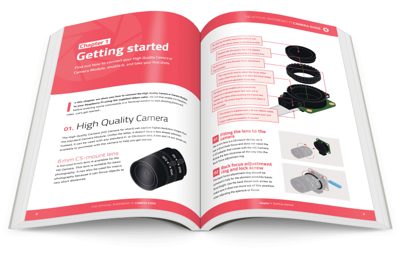
In this tutorial, we’ll show you how to attach a lens to the HQ Camera and adjust its focus and aperture settings. We’ll then use the supplied ribbon cable to connect it to Raspberry Pi, enable it in Raspbian, and enter some commands in a Terminal window to start capturing photos and video.
See also: High Quality Camera Guide and The MagPi issue 93
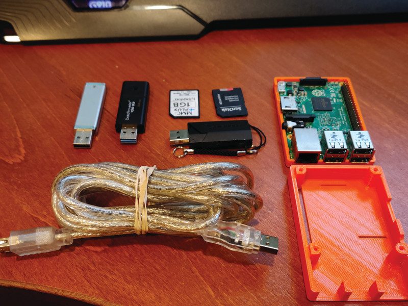
High Quality Camera: You’ll need
Using the 6 mm CS-mount lens
A low-cost 6 mm lens is available for the HQ Camera. This lens is suitable for basic photography. It can also be used for macro photography because it can focus objects at very short distances.

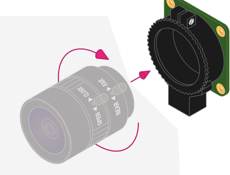
Fit the lens to the camera
The lens is a CS-mount device, so it has a short back focus and does not need the C-CS adapter that comes with the HQ Camera. Rotate the lens clockwise all the way into the back focus adjustment ring.

Back focus adjustment ring
The back focus adjustment ring should be screwed in fully for the shortest possible back-focal length. Tighten the back focus lock screw to make sure it does not move out of this position when adjusting the aperture or focus.

Adjust aperture
To adjust the aperture, hold the camera with the lens facing away from you. Turn the middle ring while holding the outer ring, furthest from the camera, steady. Turn clockwise to close the aperture and reduce image brightness. Turn anti-clockwise to open the aperture. Once you are happy with the light level, tighten the screw on the side of the lens to lock the aperture ring.

Adjust focus
To adjust the focus, hold the camera with the lens facing away from you. Hold the outer two rings of the lens; this is easier if the aperture is locked as described above. Turn the camera and the inner ring anti-clockwise relative to the two outer rings to focus on a nearby object. Turn them clockwise to focus on a distant object. You may find you need to adjust the aperture again after this.

Using the 16 mm C-mount lens
The 16 mm lens provides a higher-quality image than the 6 mm lens. It has a narrow angle of view which is more suited to viewing distant objects.
Fit the C-CS adapter
Ensure the C-CS adapter that comes with the HQ Camera is fitted to the lens. The lens is a C-mount device, so it has a longer back focus than the 6 mm lens and therefore requires the adapter.


Fit the lens to the camera
Rotate the lens and C-CS adapter clockwise all the way into the back focus adjustment ring.

Back focus adjustment ring
The back focus adjustment ring should be screwed in fully. Tighten the back focus lock screw to make sure it does not move out of this position when adjusting the aperture or focus.

Adjust aperture
To adjust the aperture, hold the camera with the lens facing away from you. Turn the inner ring, closest to the camera, while holding the camera steady. Turn clockwise to close the aperture and reduce image brightness. Turn anti-clockwise to open the aperture. Once you are happy with the light level, tighten the screw on the side of the lens to lock the aperture ring into position.

Adjust focus
To adjust the focus, hold the camera with the lens facing away from you. Turn the focus ring, labelled ‘NEAR FAR’, anti-clockwise to focus on a nearby object. Turn it clockwise to focus on a distant object. You may find you need to adjust the aperture again after this.
Connecting and using the camera
With your HQ Camera and mounted lens ready, it’s time to connect it to your Raspberry Pi and start capturing some images.
Connect ribbon cable to camera
On the bottom of the HQ Camera board, you’ll find a black plastic flap (Figure 1). Carefully pull the sticking-out edges until the flap pulls part-way out. Slide the ribbon cable, with the silver edges downwards and the blue plastic facing upwards, under the flap you just pulled out, then push the flap gently back into place with a click; it doesn’t matter which end of the cable you use. If the cable is installed properly, it will be straight and won’t come out if you give it a gentle tug; if not, pull the flap out and try again.

Connect cable to Raspberry Pi
Find the Camera port on Raspberry Pi and pull the plastic flap gently upwards. With Raspberry Pi positioned so the HDMI port is facing you, slide the ribbon cable in so the silver edges are to your left and the blue plastic to your right, then gently push the flap back into place. As before, if the cable is installed properly, it’ll be straight and won’t come out if you give it a gentle tug; if not, pull the plastic flap out and reinsert the cable. If using a Raspberry Pi Zero, its Camera port is found on the edge of the board. However, as it’s a smaller size than the regular one on other Raspberry Pi models, you’ll need a camera adapter cable to use it.
Tip! Longer cable
The HQ Camera is supplied with a standard 20 cm ribbon cable for connection to Raspberry Pi. However, longer camera cables are available from the usual online retailers.
Enable the camera
Connect the power supply back to Raspberry Pi and let it load Raspbian. Before you can use the camera, you’ll need to tell Raspberry Pi it has one connected: in the Raspbian menu, select Preferences, then Raspberry Pi Configuration. When the tool has loaded, click the Interfaces tab, find the Camera entry in the list, and click on the round radio button to the left of ‘Enabled’ to switch it on (Figure 2, overleaf). Click OK, and the tool will prompt you to reboot your Raspberry Pi. Do so and your camera will be ready to use.

Test the camera
To confirm that your camera is correctly installed, you can use the raspistill tool. This, along with raspivid for videos, is designed to capture images from the camera using Raspberry Pi’s command-line interface (CLI). In the Raspbian menu, select Accessories, then Terminal. A black window with green and blue writing in it will appear: this is the Terminal, which allows you to access the command-line interface. To take a test shot, type the following into Terminal:
raspistill -o test.jpg
As soon as you hit ENTER, you’ll see a large picture of what the camera sees appear on‑screen (Figure 3). This is called the live preview and, unless you tell raspistill otherwise, it will last for five seconds. After those five seconds are up, the camera will capture a single still picture and save it in your home folder under the name test.jpg. If you want to capture another, type the same command again – but make sure to change the output file name, after the -o, or you’ll save over the top of your first picture.

More advanced commands
The raspistill command has a list of options so long that it borders on the intimidating. Have no fear, though: you won’t need to learn them all, but there are a few that might be useful to you, such as:
raspistill -t 15000 -o newpic.jpg
The -t option changes the delay before the picture is taken, from the default five seconds to whatever time you give it in milliseconds – in this case, you have a full 15 seconds to get your shot arranged perfectly after you press ENTER.
Capture video
For shooting video, raspivid is what you need. Try it out with this Terminal command:
raspivid -t 10000 -o testvideo.h264
This records a ten-second video (10,000 milliseconds) at the default 1920 × 1080 resolution. You can also shoot slow-mo video at 640 × 480 by using:
raspivid -w 640 -h 480 -fps 90 -t 10000 -o test90fps.h264
You can use VLC to play the videos back. This application is pre-installed in the Raspbian ‘Full’ version. If it’s not, you can use the Recommended Software tool to install it.
Tip! Using VNC
By default, you won’t be able to view the camera preview window when accessing your Raspberry Pi remotely from another computer via VNC. However, there is a setting to make the window appear. Open the VNC Server menu on Raspberry Pi and go to Options > Troubleshooting, then select ‘Enable direct capture mode’.