Schlagwort: miniatures

  • The Arduino Launch Control System is a model rocket enthusiast’s dream

    The Arduino Launch Control System is a model rocket enthusiast’s dream

    Reading Time: 2 minutes

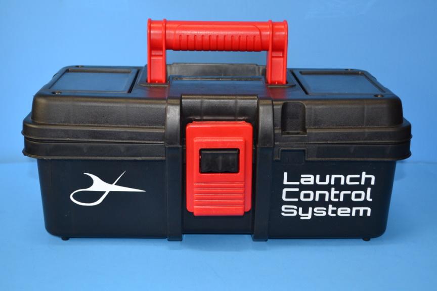
    Conventional hobby model rockets get their thrust from disposable motors containing an explosive propellant, like black powder. But unlike the gun powder in a firearm’s cartridge that uses a concussion-activated primer to ignite, model rocket enthusiasts ignite their motors using an electric arc. Simple launch controllers consist of little more than a battery, boost converter, and cables. But if you want something fancy, you should check out the Arduino Launch Control System.

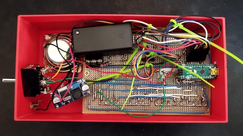
    This robust launch controller provides environmental data and a great deal of safety. Its built-in sensors provides three key data points: temperature, humidity, and barometric pressure. That information can convey valuable insight when evaluating the performance of a rocket. On the safety side, this launch controller forces several layers of redundancy and checks. To launch a rocket, the user must connect two power supplies, insert and turn a key, push the safety and fire buttons at the same time, and hold those buttons for the entire countdown. That focus on safety makes this launch controller perfect for younger hobbyists.

    The full bill of materials is quite long, but the major components are an Arduino Nano board, a 16×2 character LCD, a BMP180 barometric pressure sensor, a DHT11 temperature/humidity sensor, and a DS1370 real-time clock. The enclosure is a small 13” toolbox with chipboard panel. Chipboard is very thick card stock that easy to cut, but strong enough for an application like this. The full build details are available on the Instructables tutorial page.

    If you want all of the features of a high-end launch controller, but without the expense, then the Arduino Launch Control System makes for a great weekend project.

    The post The Arduino Launch Control System is a model rocket enthusiast’s dream appeared first on Arduino Blog.

    Website: LINK

  • This pen plotter gets nervous when observed

    This pen plotter gets nervous when observed

    Reading Time: 2 minutes

    The whole purpose of machine automation is to eliminate human needs and errors. A CNC machine doesn’t get tired, doesn’t need breaks, and performs a task exactly the same way every time. But what if that weren’t true? What if machines experienced human emotions and let it affect their work like we do? That’s the idea behind Devlin Macpherson’s Nervous Drawing Machine.

    By all outward appearances, this is just a standard two-axis pen plotter. Like many laser cutters and 3D printers, it has a stepper motors controlled by an Arduino board that follows G-code commands. A command might be something like “move the X axis 2mm to the right.” By chaining hundreds or thousands of those commands together, the machine can follow complex toolpaths that form letters, symbols, pictures, or anything else. Macpherson equipped the pen plotter with a continuously fed roll of paper so it can draw indefinitely.

    Under normal conditions, the machine plots row after row of little squares. A video camera points at the plotter as it works and the video feed streams through a website. And this is where things get interesting. If someone visits the website and watches the stream, the pen plotter becomes nervous about being observed. It will then start to make mistakes, like drawing scribbles instead of squares. Once the visitor leaves the website and the machine is unobserved once again, it will return to drawing perfect rows of squares.

    Macpherson built the Nervous Drawing Machine for his thesis project titled ICFWYWM (I Can’t Focus When You’re Watching Me). Like all good interactive art installations, it reflects the human condition.

    The post This pen plotter gets nervous when observed appeared first on Arduino Blog.

    Website: LINK

  • Substituting a flex sensor for an inexpensive light-dependent resistor

    Substituting a flex sensor for an inexpensive light-dependent resistor

    Reading Time: 2 minutes

    In order to build wearables that react to movement, most people tend to reach for accelerometers, gyroscopes, and flex sensors. But due to their higher cost, one of teacher Gord Payne’s students wanted to create a low-cost alternative that could be easily sourced and integrated into projects.

    A typical glove with finger movement tracking normally incorporates flexible strips, which vary in resistance based on the extent of their deviation from the starting angle. By reading this value with an Arduino board’s analog-to-digital converter (ADC) and mapping the resistance with a formula, the total angle can be found with decent accuracy. The student’s idea, however, substituted this special material for a flexible tube that has an LED on one end and a light-dependent resistor (LDR) on the other. When kept at the starting position, all of the light from the LED is able to hit the LDR, and any bends introduced from bending the tube cause less light to reach the other side.

    After performing a few test runs to determine the exact mapping of resistance values coming from the LDR compared to the angle of the finger, the student’s code could accurately calculate the angle based on a simple formula. To demonstrate this project, a servo was connected to the microcontroller and made to mimic how the finger is moved.

    More information can be found here on Payne’s Hackaday.io write-up

    The post Substituting a flex sensor for an inexpensive light-dependent resistor appeared first on Arduino Blog.

    Website: LINK

  • This glove translates sign language using an array of sensors

    This glove translates sign language using an array of sensors

    Reading Time: 2 minutes

    For people not familiar with American Sign Language (ASL), being able to recognize what certain hand motions and positions mean is a nearly impossible task. To make this process easier, Hackster.io user ayooluwa98 came up with the idea to integrate various motion, resistive, and touch sensors into a single glove that could convert these signals into understandable text and speech.

    The system is based around a single Arduino Nano board, which is responsible for taking in sensor data and outputting the phrase that best matches the inputs. The orientation of the hand is ascertained by reading values from the X, Y, and Z axes of a single accelerometer and applying a small change based upon prior calibration. Meanwhile, resistive flex sensors spanning the length of each finger produce a different voltage level according to the bend’s extent.

    At each iteration of the program’s main loop, a series of Boolean statements are evaluated to pick the phrase that best matches the current finger bends and hand orientation, and this data is then outputted via the UART pins to an attached Bluetooth® HC-05 module. The final component is a connected phone running a custom app that takes the incoming words from Bluetooth® and saves them for text-to-speech output when the button is pressed.

    To see more about this project, you can read ayooluwa98’s write-up here on Hackster.io.

    The post This glove translates sign language using an array of sensors appeared first on Arduino Blog.

    Website: LINK

  • This search and rescue robot creates 3D maps of disaster areas

    This search and rescue robot creates 3D maps of disaster areas

    Reading Time: 2 minutes

    If you look at footage from the search and rescue efforts following any disaster, you’ll see that first responders have a very difficult time navigating through rubble to find people in need of emergency care. They also have to take extra precautions, as gas line ruptures and other hazards present dangers they don’t normally face. To assist in those efforts, Ranit Bhowmick and his team built the SARDA (Search and Rescue Deployable Assistant) robot that can create 3D maps of disaster areas.

    SARDA is currently an early prototype and its capabilities are limited, but the idea is sound. It is a little wheeled robot that would (in theory, at least) rove around a disaster area while mapping its surroundings. It could work autonomously or an operator could guide it manually. While moving around an area, it would generate a 3D map of rigid objects, like walls and obstacles, and also health hazards like clouds of smoke, heat, or toxic gases. A computer at a control station would use that data to produce a digital 3D render of the environment that first responders could reference during their search and rescue efforts.

    The robot is affordable to build and uses only off-the-shelf components. Those include an Arduino Nano board, a pair of ultrasonic distance sensors, a temperature and humidity sensor, and a smoke sensor. The Arduino controls the drive motors through L239D drivers. The RCU (receiver and controller unit) contains an Arduino Uno and communicates with SARDA through a pair of nRF24L01 radio transceiver modules.

    Bhowmick and team created SARDA for a science fair and it is rudimentary, but functional. The mapping software can only generate simple blocks where the ultrasonic sensors detect obstacles and the positioning is based purely on open-feedback motor control. But this is a great start and something to build upon.

    The post This search and rescue robot creates 3D maps of disaster areas appeared first on Arduino Blog.

    Website: LINK

  • This reverse geocache gift box only opens at specific GPS coordinates

    This reverse geocache gift box only opens at specific GPS coordinates

    Reading Time: 2 minutes

    Geocaching is a hobby that combines the fun of a scavenger hunt with modern GPS technology. One party will hide a small cache somewhere, then post the general location and the exact GPS coordinates for other parties to find. The goal is to use GPS navigation to find the hidden cache. Often, people will sign a log or leave a small memento in the cache for others to find. Trent Wyatt took that idea and flipped it with this “reverse geocache box” that will only open when someone takes it to a specific GPS location.

    Wyatt designed this with gift-giving in mind. The box has an internal lock that isn’t accessible from the outside. The only way for the recipient to open the box and get their gift is by pushing the red button when they are at the location set by the giver. If they aren’t at the proper location, the display on the box will show the distance to the proper GPS location and how many tries they have left. The idea is that the giver will tell the recipient the general location and the recipient will have to perform triangulation to find the exact coordinates where the box will open.

    If you want to build your own Reverse Geocache Box, you can start with a hinged wooden box. You can then use any Arduino board (like an Uno or Nano) to monitor the box’s location through a serial GPS module. Before locking up the box, you will need to add the unlocking location to the Arduino sketch. When the box closes, the Arduino locks the lid using a simple servo-actuated mechanism. Power comes from a pair of 18650 lithium batteries through a 5V regulator. Distance data displays on a small 16×2 character LCD screen. You also have the option to add a small amplifier and speaker to add sound effects (like a celebration tune). You can, of course, include a secret backdoor to open the box in the event that something goes wrong.

    The post This reverse geocache gift box only opens at specific GPS coordinates appeared first on Arduino Blog.

    Website: LINK

  • This Arduino Nano-based synthesizer can produce a wide range of intriguing sounds

    This Arduino Nano-based synthesizer can produce a wide range of intriguing sounds

    Reading Time: 2 minutes

    Synthesizers have existed in their current form for several decades now. In essence, they generate simple waveforms that are then either added or subtracted together and modified through the use of filters, envelopes, and modulators to control pitch, volume, and several other characteristics. Due to their simplicity, many types of components can be combined to create them with a wide variety of unique characteristics.

    Built by Ignacio Ríos, his take on the synthesizer incorporates an Arduino Nano along with a series of buttons, potentiometers, and an amplifier to produce sounds. It starts by taking a carrier frequency that is modulated by a secondary oscillator, similar to how FM radio functions. From here, four potentiometers modify how the carrier frequency responds to the modulated wave. Another four potentiometers change the attack, decay, sustain, and release durations, all of which are read by the Nano’s onboard ADC.

    Each of the keyboard’s keys are actuated with a tactile switch that constantly gets polled for when it is either pressed or released. When pressing a key, the program updates the current note being played and each of the four channels with the computed values from the aforementioned potentiometers. Finally, the PWM pin’s pulse width is updated to reflect the new value.

    After 3D printing a shell, the 17 keys for the keyboard, and a few dials, Ignacio assembled the synthesizer together and was able to successfully play a series of varied notes. To see this in action, you can watch Ríos’ YouTube video below or check out his write-up on Instructables.

    The post This Arduino Nano-based synthesizer can produce a wide range of intriguing sounds appeared first on Arduino Blog.

    Website: LINK

  • Make your own micro FPV drone racing gate

    Make your own micro FPV drone racing gate

    Reading Time: 2 minutes

    Drone racing is an increasingly popular hobby, especially as high-performance drones get more and more affordable. Racing drones can reach 200mph and a huge part of the skill set necessary for competition is the pilot’s ability to navigate through gates at high speed. Those gates mark check points on the course, a bit like the gates that slalom skiers go through. Drone racing gates can also track time, which is the case with this DIY micro FPV drone racing gate built by YouTuber ProfessorBoots.

    This is an affordable gate meant for indoor micro FPV drone racing. It is big enough to accommodate some larger drones, but the pilot would have to have stellar finesse. For micro drones, it is perfect. The gate detects the presence of a passing drone and can time laps, recording each lap and allowing the pilot to see their best time. It also has a ring of LEDs for visibility. If desired, the user can program those LEDs to flash when a drone passes through.

    The brain of the gate is a small and affordable Arduino Nano board. It detects passing drones using a pair of ultrasonic sensors. Many similar builds only use a single ultrasonic sensor, but ProfessorBoots added a second for reliable drone detection. The enclosure and ring are 3D-printable, with a strip of WS2812B individually addressable RGB LEDs running along the outer surface of the ring. A small four-digit, seven-segment display connects to the Arduino to display the time.

    The post Make your own micro FPV drone racing gate appeared first on Arduino Blog.

    Website: LINK

  • Have you heard? Nicla Voice is out at CES 2023!

    Have you heard? Nicla Voice is out at CES 2023!

    Reading Time: 2 minutes

    As announced at CES 2023 in Las Vegas, our tiny form factor family keeps growing: the 22.86 x 22.86 mm Nicla range now includes Nicla Voice, allowing for easy implementation of always-on speech recognition on the edge.

    How? Let’s break it down.

    1. The impressive sensor package. Nicla Voice comes with a full set of sensors: microphone, smart 6-axis motion sensor and magnetometer – so it can not only listen to you, your machines, the environment around it, but also recognize gestures, vibrations and other movements. 

    2. The high-performance AI brains. Nicla Voice runs audio inputs through the powerful Syntiant NDP120 Neural Decision processor, which mimics human neural pathways to run multiple AI algorithms and automate complex tasks. In other words, it hears different events and keywords simultaneously, and is capable of understanding and learning what sounds mean.

    3. The easy connectivity features. It connects to existing devices thanks to onboard Bluetooth® Low Energy connectivity. 

    4. The effortless integration with custom boards. Thanks to its headers and castellated pins, Nicla Voice is ready to go from prototype to industrial-scale production, fitting right into any custom carrier board you develop.

    5. The Edge Impulse compatibility. In line with our mission to make complex technologies accessible to all, Nicla Voice is compatible with Edge Impulse, the leading development platform for machine learning on edge devices.

    6. The minimal power needs. And last but absolutely not least, it is so ultra-low power it can be the brain of always-on – and even battery-operated – solutions. No need to run dedicated power lines, no switches or interfaces to activate the system. It’s ready to listen, 24/7, anywhere you want to install it.

    Speechless? We’re sure you’ll find your voice soon. With Nicla Voice’s ready-to-use combination of sensors and processing power, you can prototype and develop new solutions that leverage voice detection and voice recognition, or interpret any other audio input – from machines that need maintenance to water dripping, and from glass breaking to alarms that must get through headphones’ noise-canceling features. We can’t wait to hear what you’ll create with it!

    Need to hear a pin drop? Nicla Voice is all ears. 

    To find out more, access our free online documentation or check out the technical details from the Arduino Store page.

    The post Have you heard? Nicla Voice is out at CES 2023! appeared first on Arduino Blog.

    Website: LINK

  • Arduino brings birthday cake to life

    Arduino brings birthday cake to life

    Reading Time: 2 minutes

    A good birthday cake is all about the decoration. Usually that comes in the form of fancy frosting, fondant flourishes, and crazy candles. But what if you got electronics involved? That’s the question Natasha Dzurny answered when she used an Arduino to bring a birthday cake to life with epic LED lighting.

    WS2812B individually addressable RGB LEDs, commonly referred to by Adafruit’s “NeoPixel” trade name, are unique because a user can control the color and brightness of every LED in a chain through a single data wire. Each LED passes the data along to the next, with control commands going to the addressed LED. The user can control as many LEDs as they want using only a single digital I/O pin on a microcontroller.

    In this case, Dzurny used two Adafruit 8×32 flexible NeoPixel matrices and a NeoPixel strip. The matrices display animations and messages, while the NeoPixel strip sits atop the cake to accent a small disco ball. An Arduino Nano 33 IoT board controls all of those LEDs using the Adafruit GFX library. But while hundreds of LEDs can share a single data line, power distribution is more complicated and Dzurny had to break out power injection points.

    The cool thing about using NeoPixel matrices for a cake is that Dzurny was able to cover them in a thin layer of white fondant, which acts as a natural diffuser that blends right into the design. The messages are clearly visible, but party-goers wouldn’t even notice the LEDs underneath the fondant when they’re turned off.

    The post Arduino brings birthday cake to life appeared first on Arduino Blog.

    Website: LINK

  • This project facilitates augmented reality Minecraft gaming

    This project facilitates augmented reality Minecraft gaming

    Reading Time: 2 minutes

    Augmented reality (AR) is distinct from virtual reality (VR) in that it brings the real world into virtual gameplay. The most famous example of AR is Pokémon Go, which lets players find the pocket monsters throughout their own physical region. Minecraft is the best-selling video game of all time, but lacks any official AR gameplay. So Ryan Chan tackled the problem himself and built a system that translates real world movement into control of a player’s Minecraft avatar.

    We’ll just assume that you know how Minecraft works, because you have probably played it yourself. Chan’s project works with the standard game and doesn’t require any special mods — Chan could even use this to play on others’ Minecraft servers if he chose. The system counts footsteps and converts them into forward movement in-game. It also detects real life rotational movement and replicates that movement in the game. But other actions, like attacking or swapping items, require conventional button presses.

    The key components of this project are an Arduino MKR Zero board, a MPU-6050 IMU (inertial measurement unit), and two force sensitive resistors. The IMU detects rotational movement, while the force sensitive resistors detect footsteps when worn on the player’s shoes. Four mechanical key switches trigger the other actions. Chan configured the Arduino to appear as a standard USB HID keyboard and mouse when plugged into a computer, so Minecraft accepts the control commands without issue. To tidy everything up, Chan designed a custom PCB that hosts the aforementioned components.

    Using this system for Minecraft gaming is tricky, as it requires plenty of real world open space to navigate the virtual world. But with access to a large park, it lets the player enjoy an AR Minecraft experience.

    The post This project facilitates augmented reality Minecraft gaming appeared first on Arduino Blog.

    Website: LINK

  • Nifty cam-following plotter can draw many shapes

    Nifty cam-following plotter can draw many shapes

    Reading Time: 2 minutes

    Before CNC (computer numerical control) came along, automated machines utilized mechanisms like cams and tapers to act as guides. Those are physical components with precise contours meant to guide the tool, like an artist tracing lines with a pantograph. Such mechanisms are uncommon today, as CNC is far more versatile and much easier to implement. But Mr Innovative turned to those traditional techniques to build this cam-following plotter that can draw many shapes.

    A “cam” is a rotating or pivoting component in a mechanism, which has an irregular profile to control the actuation of something. Internal combustion engines, for example, often contain rotating cams that to open and close the valves at the proper times. In this case, the plotter’s cam controls the movement of the pen in the X axis. Wider portions of the cam push the pen further right, while narrower portions of the cam allow the pen to move left. A rubber band pulls the pen arm cam follower tight against a cam. The paper moves at a constant rate in the Y axis, and its speed combined with the shape of the cam determine the resulting plot shape.

    This machine will look familiar to those of you who have seen a Mr Innovative project in the past. It uses an Arduino Nano board paired with Mr Innovative’s own driver board design to control the two motors. One stepper motor controls the rotation of the cam and a second stepper motor controls the paper feed. The user can set the number of cam rotations using a Nextion touchscreen LCD panel. Mr Innovative 3D-printed the mechanical parts and mounted them to a small sheet of wood, with a standard linear rail and bearing restricting the movement of the pen arm to the X axis. It can’t draw any shape, but this machine is quite versatile and can produce quite a few interesting plots.

    [youtube https://www.youtube.com/watch?v=tyz6GOAZor0?start=127&feature=oembed&w=500&h=281]

    The post Nifty cam-following plotter can draw many shapes appeared first on Arduino Blog.

    Website: LINK

  • This train of trash bins moves to the curb with the press of a button

    This train of trash bins moves to the curb with the press of a button

    Reading Time: 2 minutes

    Once a week, millions of people set out their trash cans next to the curb for collection the following day, which many consider to be extremely annoying or laborious. So rather than manually dragging out the garbage and recycling bins, the YouTuber known as Max Maker decided to build a system that could automate the task at the touch of a key fob button.

    Max’s idea involved creating a single track that would span from the back garden area all the way down the driveway to the curb. From here, a train consisting of several flat carts with wheels underneath would be connected together in addition to a single locomotive cart at the rear. The first version of the locomotive used a windshield wiper motor, controlled by an Arduino Uno and motor driver board, to rotate a pair of rubber wheels along the lower track. However, the lack of power from the windshield wiper motor combined with the lack of grip from the wheels meant the heavy weight of the loaded trash cans could not be moved uphill.

    For better grip in less-than-ideal conditions, the drive wheels were replaced by a rack-and-pinion assembly that is either raised or lowered into place to move the locomotive along the track. Power is provided by a rechargeable power tool battery pack, and it gets charged thanks to a set of contacts that engage at the end of the track. For more information about this project, you can watch Max’s video below!

    [youtube https://www.youtube.com/watch?v=VhYEOG9LOIk?feature=oembed&w=500&h=281]

    The post This train of trash bins moves to the curb with the press of a button appeared first on Arduino Blog.

    Website: LINK

  • Roving Rock ‘Em Sock ‘Em Robots make the perfect Secret Santa gift

    Roving Rock ‘Em Sock ‘Em Robots make the perfect Secret Santa gift

    Reading Time: 2 minutes

    As part of what has become an annual holiday tradition, several YouTube makers coordinated their efforts this year for a Secret Santa exchange. Returning participant James Bruton drew Emily the Engineer and found inspiration for his gift from an automatic boxing glove that she built. Taking that idea and running with it, he created a pair of Rock ‘Em Sock ‘Em Robots that can drive around and compete in real-life bouts.

    The two 3D-printed robots, which are obviously red and blue, roam around on two driven wheels and punch with massive fists. That fists attach magnetically to automatic reciprocating punching mechanisms very similar to the one Emily the Engineer designed. If one robot pilot is able to punch the fist off of the opposing robot, they win the round. To kick off another round, all the players have to do is snap the fist back onto the magnetic mount.

    Arduino Nano boards control both robots as well as both RC transmitters, for a total of four Arduino boards. Bruton paired each Arduino with an nRF24L01 radio transceiver module, which facilitates the communication between the robots and their RC transmitters. Each robot has three DC motors: two for the drive wheels and one for the reciprocating punching mechanism. The onboard Arduino controls the motors through IBT-4 motor drivers. Finally, the transmitters contain joysticks for moving the robots and triggers for activating the punching mechanism.

    Now Emily the Engineer can duke it out on a grand scale whenever she wants, throwing punches via a mechanism that she devised.

    The post Roving Rock ‘Em Sock ‘Em Robots make the perfect Secret Santa gift appeared first on Arduino Blog.

    Website: LINK

  • This flip-dot display acts like an Etch A Sketch

    This flip-dot display acts like an Etch A Sketch

    Reading Time: 2 minutes

    Every year, several of the biggest names in the maker world on YouTube get together for an international Secret Santa exchange. Each participate gets to decide on a gift for the assigned recipient and the only rule is that they must make the gift themselves. Sam Battle, of the LOOK MUM NO COMPUTER YouTube channel, made this awesome flip-dot display Etch A Sketch for Ruth and Shawn of KidsInventStuff.

    Flip-dot displays used to be common for bus-mounted route readouts and ETAs in airport terminals, as they are reconfigurable and very readable at a distance. But the low cost and ubiquity of large LCD, OLED, and plasma screens made them obsolete over the last couple of decades. Few companies still manufacturer them and so Battle had to use a vintage flip-dot display panel. It works using a matrix circuit, like an LED panel. By applying current, one can flip the state of an entire row, entire column, or a single pixel according to polarity and it will remain at the set state.

    The same works with potential difference, which is how Battle chose to control his panel. Instead of reversing polarity, he can apply either ground or 10V (relative to 5V) to flip the state. An Arduino Nano controls the state changes through the panel’s built-in multiplexer chips. Battle then connected a few momentary toggle switches to the Arduino that let the user “draw” like they would on an Etch A Sketch toy. They can clear the entire panel, move the “cursor” while setting pixels to yellow, or move the cursor while setting pixels to black.

    Battle packaged the panel and control switches in a simple wooden frame with a Plexiglass cover. It is a truly unique gift and one of the most creative uses for a flip-dot display that we’ve come across.

    The post This flip-dot display acts like an Etch A Sketch appeared first on Arduino Blog.

    Website: LINK

  • This clever clock displays the time in magnetic fields

    This clever clock displays the time in magnetic fields

    Reading Time: 2 minutes

    You’ve probably seen videos of people moving magnets near iron dust, which results in the dust aligning itself to the patterns created by the magnetic fields. Magnetic viewing film works the same way, but with the dust in an oil suspension sitting in the gap between two sheets of transparent plastic. By moving that film over magnets, one can see the magnetic fields almost like they’re on an LCD panel. Moritz v. Sivers took advantage of that fact to build a clock that displays the time on magnetic viewing film.

    Sivers did this by putting a small sheet of magnetic viewing film in a 3D-printed frame over four wheels. They arranged numbers around the circumference of those four wheels, a bit like an analog clock face. The numbers are made of magnetic foil, so their magnetic fields appear on the viewing film as the wheels rotate. Four boxes stenciled onto the viewing film indicate which numbers make up the current time, so reading this magnet clock is as easy as any digital clock.

    Each of the four wheels has its own pancake-style stepper motor. An Arduino Uno board controls those motors through a CNC Shield outfitted with stepper drivers. The Arduino keeps track of the current time using a DS3231 real-time clock (RTC) module. For now, the user must manually set the zero position of each wheel each time they turn the clock on, but Sivers plans to add Hall-effect sensors soon to automate that process. The numbers are a little faint due to the weak magnetic fields produced by the foil, but are still completely readable.

    The post This clever clock displays the time in magnetic fields appeared first on Arduino Blog.

    Website: LINK

  • Announcement: Project Hub is evolving

    Announcement: Project Hub is evolving

    Reading Time: 2 minutes

    Encouraging people to share projects and tutorials has always been central to Arduino’s mission of democratizing technology. Learning from the work of others is very important  as we always felt that most makers like to start from an existing project and evolve from their own creation. If you’ve been following Arduino for a while you know we went through a few tools in our history, from “Playground” to “Scuola” arriving at our current “Project Hub” in search of always simpler and better ways to share.

    In 2014, we collaborated with Hackster.io to establish “Project Hub”, based on the Hackster platform. Together we grew a space that hosts thousands of well-documented projects submitted by all of you. Although this partnership is very important to us, Arduino will move Project Hub in-house. Building our own project sharing platform allows us to further integrate with Arduino Cloud and better align with our new features.

    Here’s what to expect: The new Project Hub will launch in beta on December 29th and will be available at the usual address https://arduino.cc/projecthub — bookmark it now! The old Project Hub will no longer be available after the end of December.

    If you have created your projects with an Arduino account they will be automatically migrated to the new platform with this schedule:

    • Phase 1: Projects created before August 2022 will be available on the new platform on January 1, 2023.
    • Phase 2: New projects created between September 2022 and December 2022 will be available on the new platform on February 1, 2023.

    If you’ve used your Hackster.io account you’ll have to re-register on Arduino and transfer them manually.

    We are planning an amazing competition with great prizes to encourage users to share even more projects. We really want to break all the records. Stay tuned for the details that will be announced in January.

    We want to thank Hackster.io for all the help and support throughout the years and we can’t wait to  continue exploring our partnership, bringing more engaging activities to our global communities.

    The post Announcement: Project Hub is evolving appeared first on Arduino Blog.

    Website: LINK

  • The Infineon team’s XXL Chatbot offers you yuletide greetings

    The Infineon team’s XXL Chatbot offers you yuletide greetings

    Reading Time: 2 minutes

    Infineon is one of the world’s largest semiconductor manufacturers, but the company is made up of regular people like any other. Many of those people just happen to be engineers and they like to build gadgets and gizmos like the rest of us. Following a water cooler discussion about who had the biggest 3D printer, the Infineon team decided to create this delightful XXL Chatbot to offer yuletide greetings.

    The adorable robot was designed after the Infineon Chatbot avatar that offers virtual assistance on the Infineon website. While that internet Chatbot can respond to natural language questions, this XXL Chatbot can only emote through its animated eyes and chest-mounted RGB LED matrix. The team 3D-printed the robot’s body in several sections on a Creality Ender-5 Plus and the assembled figure is quite large, hence the “XXL” designation.

    They animated the eyes using two custom PCBs, each of which has a diameter of 60mm and contains 101 SK6812MINI individually addressable RGB LEDs. They controlled those with a pair of Infineon XMC2GO microcontroller development boards. The chest display is a flexible 64×32 RGB LED matrix from Adafruit, which conforms to the cylindrical curve of the robot’s torso. They controlled that LED matrix with an Arduino Mega 2560 board through Adafruit’s RGB Matrix Shield. It displays a Christmas tree animation derived from z1co’s animation set for 32×32 matrices.

    The result is a cheerful and adorable robot that fits perfectly with the holiday season!

    The post The Infineon team’s XXL Chatbot offers you yuletide greetings appeared first on Arduino Blog.

    Website: LINK

  • Check out James Bruton’s robotic camera operator

    Check out James Bruton’s robotic camera operator

    Reading Time: 2 minutes

    We’re ages past the time when a YouTuber could get away with sloppy camera work. If someone wants to achieve any level of success making videos today, they need near-professional camera equipment. But even that equipment isn’t enough if it’s still used for static shots. Many makers build sliders and other rigs, but James Bruton skipped those small steps and jumped straight to a versatile robotic camera operator.

    Bruton wanted to capture dynamic videos at any time of day or night without hiring a live-in camera operator and this robot is the result. It can drive around and has complete control over the mounted DSLR camera. It can follow pre-programmed movement patterns, can use tracking to stay focused on Bruton, or a combination of the two to change perspective while staying centered on Bruton. It can also automatically zoom in and out based on motion to ensure that anything interesting is in frame. Bruton can even trigger additional features using foot switches, such as raising a robotic thumbs-up into the frame.

    This robot is quite complex and Bruton’s video focuses on features over hardware details, but he does tell us that the robot has both an Arduino Mega 2560 development board and an NVIDIA Jetson Nano single-board computer. The Arduino handles the low-level control of the motors, while the Jetson does the heavy computer vision processing. The robot’s base contains three motor-driven omniwheels, so it can drive smoothly in any direction. The camera mount pans and tilts, and a servo spins the zoom ring. Bruton 3D-printed most of the robot’s physical parts, with only a handful of aluminum extrusion for the vertical structure. With this robot in his arsenal, we expect Bruton’s videos to be far more dynamic in the future

    The post Check out James Bruton’s robotic camera operator appeared first on Arduino Blog.

    Website: LINK

  • Ghostwriter is a gorgeous typewriter with an onboard AI co-writer

    Ghostwriter is a gorgeous typewriter with an onboard AI co-writer

    Reading Time: 2 minutes

    Much to the consternation of those of us who write for a living, AI writers are gaining traction as their capabilities increase. The hot name in the AI content creation industry at the moment is ChatGPT, which is powered by OpenAI’s GPT-3 engine. With the right input and direction, GPT-3 can output some impressive writing. To harness that power in a co-writing assistant, Arvind Sanjeev built the Ghostwriter.

    Ghostwriter is a vintage Brother electric typewriter retrofitted with modern hardware that lets it access and utilize the GPT-3 API (application programming interface). The user can type a query onto paper, such as a writing prompt or question, and GPT-3 will return a result that also prints out on the paper. By guiding GPT-3 with suitable prompts, the user can receive as much AI-generated text as they like. They might then edit that text for publication, use it as-is, or showcase the manuscript as an art piece.

    In addition to the writing capability, Ghostwriter is gorgeous. Arvind cleaned up the vintage machine with a fresh coat of paint and added orange accents that enhance the design. A tiny OLED screen shows an animated logo and status information. Inside the machine are two modern components important to the new functionality: an Arduino Uno board and a Raspberry Pi single-board computer. The Arduino both monitors the typewriter’s keyboard matrix to detect key presses and triggers key presses to print out the GPT-3 results. It sends key presses to the Raspberry Pi and receives text strings in return, and the Raspberry Pi connects to OpenAI’s API.

    The result is beauty and functionality in the same package. It is an interactive art piece that demonstrates the power of cutting-edge AI services.

    The post Ghostwriter is a gorgeous typewriter with an onboard AI co-writer appeared first on Arduino Blog.

    Website: LINK

  • Predicting potential motor failures just using sound

    Predicting potential motor failures just using sound

    Reading Time: 2 minutes

    Nearly every manufacturer uses a machine at some point in their process, and each of those machines is almost guaranteed to contain at least one motor. In order to maintain uptime and efficiency, these motors must always work correctly, as even a small breakdown can lead to disastrous effects. Predictive maintenance aims to achieve this goal while also not going overboard in trying to prevent them entirely by combining sensors with predictive techniques that can schedule maintenance when a failure is probable.

    Shebin Jose Jacob’s solution utilizes the Arduino Nano 33 BLE Sense, along with its built-in microphone, to capture audio and predict when a motor is about to fail. He achieved this by first creating a new Edge Impulse project and gathering samples for four classes of sound: OK, anomaly 1, and anomaly 2, as well as general background noise. After designing an impulse and training a classification model on the samples, he was able to achieve an impressive accuracy of about 95% on the test samples.

    The final step involved deploying the model as firmware for the Arduino, which would allow it to classify sounds in real-time by continuously reading from the microphone. Whenever an anomaly is detected, a red LED at the top illuminates.

    You can read more about the project here on its Edge Impulse tutorial.

    The post Predicting potential motor failures just using sound appeared first on Arduino Blog.

    Website: LINK

  • Grimmboy is an RFID music player designed for kids

    Grimmboy is an RFID music player designed for kids

    Reading Time: 2 minutes

    Kids, like full-sized humans, love music. But most music players are designed for adult dexterity and user interface familiarity, which makes them difficult for young children to operate. For many parents, Amazon’s Alexa and similar services are the answer, as kids can simply ask a device to play the song they want. But to give them a less noisy way to play music and retain some control over what they can listen to, consider building the Grimmboy Arduino-based RFID music player for kids.

    Because Grimmboy is for kids, the controls are as simple as possible. There is a pause/unpause button, a volume dial, and a status LED — that’s it. To select a song, album, playlist, recorded story, or any other audio file, the child simply taps one of the RFID cards to the device. The cards, which are laminated with nice cassette tape graphics, contain MiFare Ultralight C RFID tags that the parent can program with lists of four-digit track IDs. Grimmboy reads the card’s track ID list and starts playing the files with those IDs.

    The three key components for this project are an Arduino Nano board, a DFPlayer Mini MP3 player module, and an MFRC522 RFID module. In addition, Grimmboy contains a TP4050 battery charger/booster module with an 18650 lithium battery. Any LED will work for the status light, the pause button is a standard momentary push button, and the volume dial is a 1K potentiometer. The DFPlayer Mini has a built-in SD card slot for song storage and so everything works offline without an internet connection. The demonstrated enclosure was made of wood, but parents can get creative with the project to make something suited to their own children.

    The post Grimmboy is an RFID music player designed for kids appeared first on Arduino Blog.

    Website: LINK