Schlagwort: microscope
-

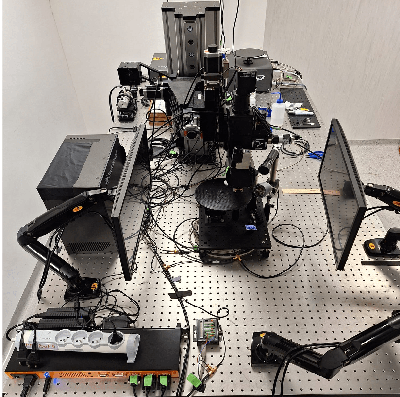
Using Arduino UNO to sync a visual neuroscience lab
Reading Time: 3 minutesCommon research methods to study the visual system in the laboratory include recording and monitoring neural activity in the presence of sensory stimuli, to help scientists study how neurons encode and respond, for example, to specific visual inputs. One of the biggest technical problems in the neural recording setups used in such…
-

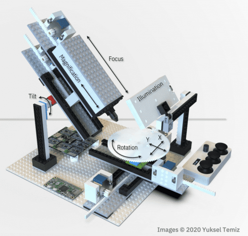
Raspberry Pi High Quality Camera powers up homemade microscope
Reading Time: 3 minutesWow, DIY-Maxwell, wow. This reddit user got their hands on one of our new Raspberry Pi High Quality Cameras and decided to upgrade their homemade microscope with it. The brains of the thing are also provided by a Raspberry Pi. Key features Raspberry Pi OS 8 MegaPixel CMOS camera (Full HD 30…