Schlagwort: mega

  • Opa is an open source boat bot that navigates the open water

    Opa is an open source boat bot that navigates the open water

    Reading Time: 2 minutes

    Arduino TeamNovember 16th, 2021

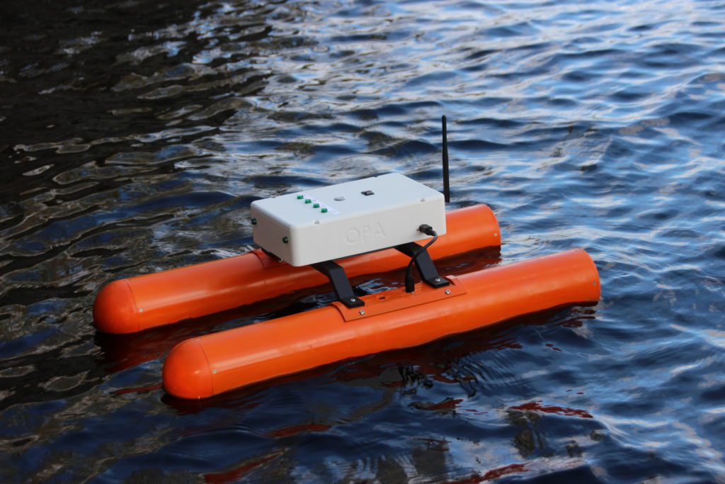
    Starting with an idea in 2019, Redditor wesgood has been steadily working on the Opa — an autonomous 3D-printed boat that can navigate open water while relaying its telemetry back in real-time to a client device over WiFi. After creating a small prototype, Wes built a second one that featured a pair of pontoons held together with a couple of struts and a central platform. This design contains a single water jet that is situated in the back of each pontoon that takes in water and shoots it out at a high velocity, similar to a jet ski. Best of all, they can be independently throttled which eliminates the need for a rudder. 

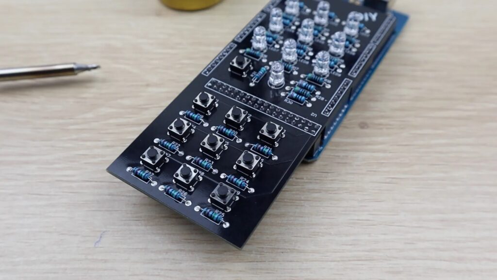
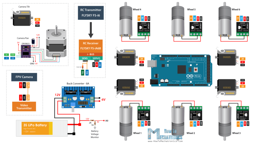
    As far as circuitry goes, the Opa houses an Arduino Mega that has a custom shield on the top for controlling the pump motors and reading data from the onboard 9-DOF IMU and battery voltage/current sensors. An auxiliary Raspberry Pi runs Ubuntu Server, and its job is to coordinate data coming from a GPS receiver and information from the Arduino Mega with a wireless client device. 

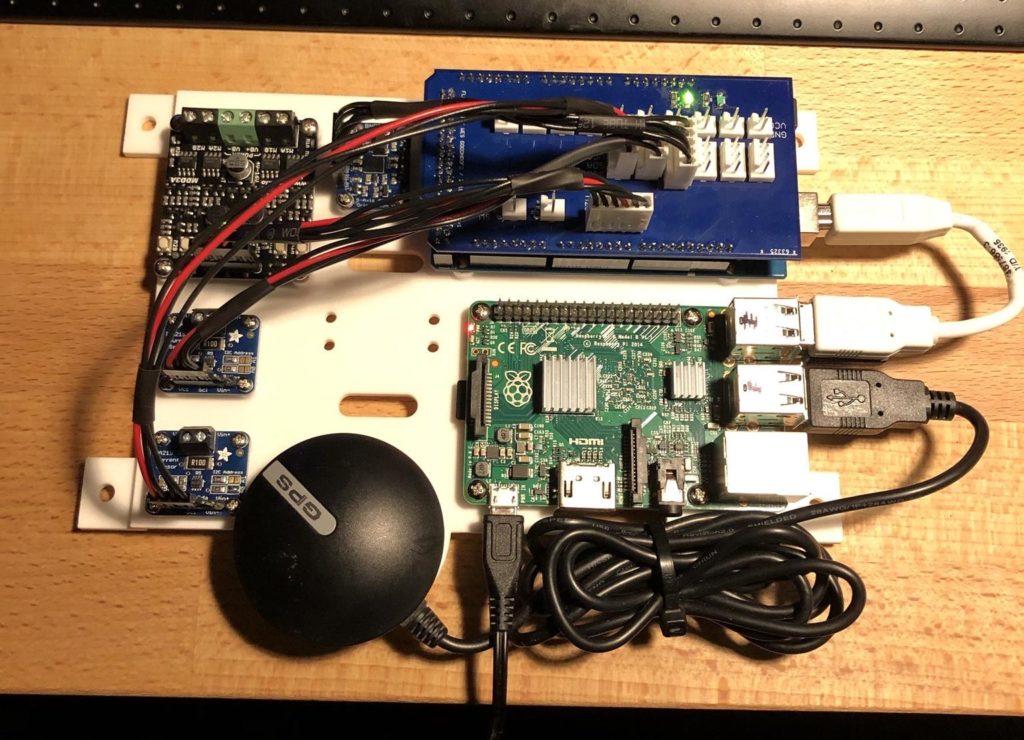
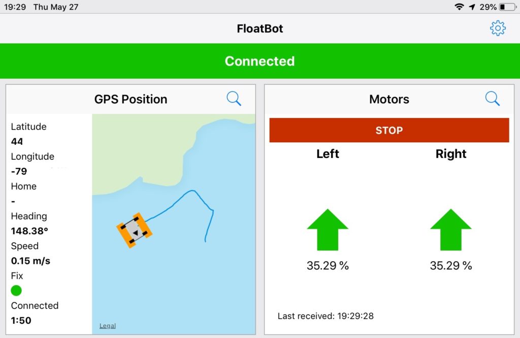
    After getting the necessary software loaded onto the Arduino and Raspberry Pi, Wes placed them inside of a watertight enclosure on the top of the boat. His mobile app could then be used to see relevant telemetry, power consumption, and the current location of the raft overlaid on a map. Additionally, the user has the option to manually pilot the boat if they so desire as well. 

    To see more information about how the Opa was developed, visit Wes’ Imgur gallery here.

    Website: LINK

  • Cascading LED stair lights prevent late night tumbles — and put on a show during parties

    Cascading LED stair lights prevent late night tumbles — and put on a show during parties

    Reading Time: 2 minutes

    Arduino TeamNovember 15th, 2021

    Stephen Gidge and his roommate have a poorly-lit flight of stairs in their home. That isn’t a big deal during the day, but it is a recipe for late night tumbles. They could have setup some nightlights or installed a new hall light, but they were both experienced with Arduino and so they created these cascading LED star lights instead.

    Under each step on their staircase, Gidge and his roommate mounted a strip of white LEDs. When someone approaches the bottom stair, each step lights up in a sequence starting from the bottom and going up. If someone approaches the top stair, the opposite happens and the sequence goes down. In either case, all of the stairs will remain lit for a little while to give the climber enough time to complete their journey. There is also a cooldown delay, so the “down” sequence doesn’t activate when someone reaches the top step as they’re ascending the stairs.

    An Arduino Mega controls each LED strip individually via one of 16 transistors, though all of the strips share power. The Arduino detects people using a pair of ultrasonic sensors — one at the top of the stairs and the other at the bottom. That was enough to provide lighting for safe midnight snack runs, but the duo took it one step further by adding music-reactive effects that are great for parties. The Arduino listens for music through a MAX9814 microphone module and flashes the stairs like a massive bass visualizer, enhancing shindig ambiance.

    Website: LINK

  • Arduino enables USB mouse support on custom 6502 homebrew computer

    Arduino enables USB mouse support on custom 6502 homebrew computer

    Reading Time: 2 minutes

    Arduino TeamOctober 21st, 2021

    The MOS Technology 6502 was one of the most popular processors of the 8-bit era. It found a home in legendary computers like the Commodore 64, Acorn Electron, BBC Micro, and Apple II. Even the NES had a custom implementation of the 6502. Because the 6502 is so well documented, it is possible for today’s enthusiasts to use it in their own homebrew computers. To enhance their DIY 6502 computer, rehsd used an Arduino to add USB mouse support.

    This homebrew computer is a Ben Eater design, which rehsd modified and created a PCB to streamline. It operates like most computers from the late ’70s and early ’80s. Computers back then didn’t support USB mice — the USB standard wouldn’t even exist until 1996. Joysticks were common, but graphical user interfaces and the mice to support them were not. So rehsd had to find a way to get a USB mouse talking to his 6502 processor. They settled on an Arduino Mega as an adapter.

    The mouse connects to the Arduino through a USB host shield, which lets the board read data coming from standard USB devices. The Arduino runs a sketch that polls the mouse data and then sends that data to the 6502 through the VIA (Versatile Interface Adapter). It first triggers interrupts on the VIA and then writes the mouse data to the VIA ports. Code written in assembly runs on the 6502 and reads the mouse data after the interrupts. To demonstrate the mouse, rehsd wrote a simple drawing program that would have been a hit in 1978.

    [youtube https://www.youtube.com/watch?v=FMOCs9LEkKQ?feature=oembed&w=500&h=281]

    Website: LINK

  • PocketView is an LED display that shows info through clothes and other fabrics

    PocketView is an LED display that shows info through clothes and other fabrics

    Reading Time: 2 minutes

    Arduino TeamOctober 16th, 2021

    When receiving a notification on your phone, it can be a tedious process to take the device out of a pocket, unlock the screen, and then read the message. In order to make viewing simple information much faster, University of Waterloo researchers developed a small pocketable display that can shine images and text through fabric. This means seeing the current time or directions can be done far more quickly since all the user has to do is look down. 

    The technology driving this system consists of an Arduino Pro Mini board, an HC-05 Bluetooth module for receiving data from a host phone, an 8×8 RGBW NeoPixel matrix, and a single 420mAh LiPo battery cell for power. All of these components were assembled into a single unit and placed within a 3D-printed enclosure that can easily fit into the user’s pocket. 

    After studying how LEDs interact with various types of fabrics by using an Arduino Mega, the team gathered 12 participants to see how effective their smart display, called the PocketView, was at showing important information. Once several tasks had been performed by the group, they consistently rated the LEDs to be a better viewing experience compared to looking at a phone.

    [youtube https://www.youtube.com/watch?v=yfvURj22Alg?feature=oembed&w=500&h=281]

    To read more information about the PocketView and the plans the team has for it, you can view their paper here.

    Images: Antony Albert Raj Irudayaraj, et al.

    Website: LINK

  • Instantly test your cables by plugging them into this device

    Instantly test your cables by plugging them into this device

    Reading Time: 2 minutes

    Arduino TeamOctober 7th, 2021

    Cables come in a wide variety of styles and attempting to diagnose a potential fault in one of their tiny wires can be tricky, especially without access to fancy test equipment. To combat this problem, TechKiwiGadgets created a small device called the Touch Screen Cable Tracer, which has several varieties of connectors on both ends that allow for a USB and RJ45 cable to be plugged in and subsequently tested. 

    The board selected for this project was an Arduino Mega due to its large amount of RAM and GPIO pins. Placed on top of this was an ILI9325 2.8” TFT screen, which shows the menu for the cable tracing device and the current state of the attached cable. TechKiwiGadgets also designed, fabricated, and assembled a custom cable tracer shield that snaps onto the Arduino and exposes a mirrored set of connectors on either end. 

    After putting the Touch Screen Cable Tracer together and placing it into a custom enclosure, it was time to test it out. There are two modes (auto and manual) that can be used to select the type of cable being used. Once the cable has been detected, the Mega attempts to pass current through the wires and read it on the other end. If a fault has occurred, it shows up on the screen as a missing conductor. 

    If this unit looks familiar, that’s because it was based on an earlier version previously covered on our blog. However, the Touch Screen Cable Tracer is 70% smaller than its predecessor and employs the custom shield and snap-together parts to eliminate meticulous soldering. More details on the device can be found in TechKiwiGadgets post here.

    [youtube https://www.youtube.com/watch?v=wNKpWFi9JJM?feature=oembed&w=500&h=375]

    Website: LINK

  • Old dining table converted into the ultimate poker table using Arduino and LEDs

    Old dining table converted into the ultimate poker table using Arduino and LEDs

    Reading Time: 2 minutes

    Arduino TeamSeptember 29th, 2021

    Poker is a fun game to play with a group of friends or as part of a league, and manually having to keep track of turns by passing a dealer chip around can get tiresome… quickly. Redditor tatey13 had the idea to build a custom poker table with some extra features that makes playing easier and more fun. 

    The table started off as an old dining room table, which was promptly sanded and had a large oval cut from its center to make room for the lighting and a soft play surface. Additionally, eight spaces were created around the table at even intervals that each have a metal container and a light-up pushbutton for getting user inputs. A long LED strip was also glued to the inner edge of the table to provide information about the current turn and timing.

    In order to control everything, an Arduino Mega was selected due to its large amount of flash storage and GPIO pins. It begins by waiting for players to join, and after 20 seconds have elapsed from the first button press, the game starts. The dealer is chosen randomly, and the two spots to their immediate left are designated as the small and large blinds. If a player is taking too long, another player and the dealer can start a timer to move things along. Once everyone except a single player is remaining, the game is over, and the winner is shown with green LEDs. 

    You can see the table in action by watching tatey13’s video below!

    [youtube https://www.youtube.com/watch?v=0Zq0J9BWh0Y?feature=oembed&w=500&h=281]

    Website: LINK

  • AugLimb is the extra arm you didn’t know you needed

    AugLimb is the extra arm you didn’t know you needed

    Reading Time: 2 minutes

    AugLimb is the extra arm you didn’t know you needed

    Arduino TeamSeptember 24th, 2021

    As a maker, you probably have a third hand for your soldering station. They come in handy when you need to hold a component, PCB, solder, and soldering iron all at the same time. But an extra hand would be useful for a wide range of other everyday activities. That’s why this team of researchers created a compact robotic third arm called AugLimb.

    While robotic augmentations aren’t a new idea, they aren’t often as usable as AugLimb. This robotic arm is lightweight and compact, making it comfortable to wear. It can’t lift much weight, but it is very dexterous thanks to seven degrees of freedom and an extendable gripper. It attaches to the wearer’s bicep and folds up when not in use. When it is time for action, AugLimb unfolds and reaches further than the user’s own arm.

    An Arduino Mega board drives AugLimb’s various motors. Those include two shoulder servos, an elbow servo, two wrist servos, a scissor extension motor, and two gripper servos. The scissor extension increases reach by up to 250mm. At this time, a second human operator has to control AugLimb’s movement. But the team hopes to introduce control schemes that let the user operate the robotic limb on their own.

    [youtube https://www.youtube.com/watch?v=WyTDA7tjCjM?feature=oembed&w=500&h=281]

    AugLimb is a prototype, but Haoran Xie, a member of the team behind the project, said “We believe that AugLimb will be as popular as smart watches in the near future, as anyone from an elder to a child can comfortably wear it for the whole day.”

    Image: Haoran Xie / Zeyu Ding

    Website: LINK

  • Emulate the legendary Altair 8800 on your Arduino Mega

    Emulate the legendary Altair 8800 on your Arduino Mega

    Reading Time: 2 minutes

    Arduino TeamAugust 25th, 2021

    The Altair 8800 is one of the most important machines in computer history and many consider it to be the first personal computer. But not many computer users today would recognize it as such. At release, it couldn’t even output video and users could only interact with the Altair 8800 through a terminal or the front panel. Now you can relive history by emulating an Altair 8800, complete with front panel, on your Arduino Mega.

    The front panel on the Altair 8800 contained several status lights and toggle switches. Those are cryptic when compared to our modern graphical interfaces, but the Altair 8800’s front panel was integral for working with the machine. Users would load programs and even key in bootloaders using the front panel. The panel would also give you useful debugging information, such as if data was moving from one memory address to another. Interacting with that front panel is a necessity if you want to get the full Altair 8800 experience.

    This Instructables tutorial explains how you can do that using just an Arduino Mega and your computer — no other hardware is necessary. After flashing the provided code, the emulator will boot into MITS Altair 4k BASIC, which was Microsoft’s first software and was coded by Bill Gates himself (along with two other programmers). You can communicate with the emulator through the Arduino serial monitor, similar to how a ’70s computer user would have used a terminal. The serial monitor will also display an ASCII representation of the Altair 8800’s front panel that reacts to your actions and programs.

    If you’ve ever wanted to experience the Altair 8800 for yourself, this is a great way to do so.

    Website: LINK

  • Keep tabs on your daily runs with this interactive tracker

    Keep tabs on your daily runs with this interactive tracker

    Reading Time: 2 minutes

    Arduino TeamAugust 18th, 2021

    Being able to keep oneself accountable while working out is a vital component to almost any good exercise plan, since repetition is the key to success. In response to their significant other wanting a way to track their workouts throughout the week, Instructables user smooth_jamie set out to build a highly interactive device that gives the person using it motivation to continue on after accomplishing the day’s goal. 

    The project largely consists of a large rectangular enclosure, which houses a series of seven 128×32 OLED screens, along with a single push button next to each one. Just across from the displays is a string of WS2812B LEDs that correspond to that day’s achievement or lack thereof. Jamie had run into the issue of the OLEDs having hardcoded I2C address, so they were forced to use an I2C multiplexer breakout. They also wanted for the device to play a short song to really commemorate meeting that day’s goal, so a speaker and amplifier circuit was added onto the Arduino Mega.

    The final step of building this daily run tracker was the code, as it had to handle several different tasks. New targets are entered by holding down a given day’s button and then using the up and down buttons to set it. When the actual distance is entered, the string of RGB LEDs will begin to flash and a tune plays if the goal is met, and the LED next to it turns either red or green afterwards as a reminder.

    To read more about the project, you can view its Instructable here and check out a short demo below!

    Website: LINK

  • Arduino-based control panel streamlines laser cutting

    Arduino-based control panel streamlines laser cutting

    Reading Time: 2 minutes

    Arduino TeamAugust 11th, 2021

    Laser cutters require quite a lot of power and laser tubes need active water cooling, which means you need a coolant reservoir and a water pump. You also need an exhaust fan to remove smoke, which will reduce the laser’s efficacy. Add in a computer, positioning laser, etc., and you’ve got quite a lot to control. That’s why Kaleb Clark used an Arduino to create a control panel for his laser cutter.

    This control panel provides several toggles switches, which Clark can flip to turn on the water pump, the air assist, and so on. Each switch has a corresponding WS2812B individually-addressable RGB LED indicator light. There are also status lights that tell him if the air pressure and water flow are in the correct range. Instead of messing around with extension cords and outlets, he can flip all the switches in sequence and then start cutting. When the job finishes, he can flip them all back off.

    Those switches mount onto a custom acrylic panel attached to the laser cutter and there is a separate sheet metal enclosure that contains all the relays. In addition to the switches and status lights, the control panel houses the laser cutter’s current meter. An Arduino Mega monitors the toggle switches and activates the relays according their positions. The board also monitors an air pressure sensor and water flow sensor to ensure that they are active, since improper cooling can destroy the expensive laser tube and a lack of air assist can damage parts.

    [youtube https://www.youtube.com/watch?v=vk-KRrEeDbU?feature=oembed&w=500&h=281]

    Website: LINK

  • An open source desk to showcase your projects, complete with swappable panels

    An open source desk to showcase your projects, complete with swappable panels

    Reading Time: 2 minutes

    Arduino TeamAugust 4th, 2021

    Almost every maker has run into the problem of not being able to find a convenient display or power source for their project prototype, and thus leading to minor delays and some frustration. However, YouTuber Another Maker has come up with an open source desk concept that makes finding these things simple. The system he built uses a large grid of swappable panels that can simply slide into place within a wooden frame. Behind these are a few devices for both power and connectivity, such as power strips, an Ethernet switch (with PoE capabilities), and an HDMI switch for changing between a Raspberry Pi and a PC.

    So far, only a single specialized panel has been constructed, although Another Maker has plans for more of them. This current iteration features an array of 30 momentary pushbuttons that all feed into an Arduino Mega. When one of these labeled buttons are pressed, a command is sent via the Ethernet shield to an adjacent home server, where it can control an RGB light strip or interact with an MQTT client. 

    To the right of the large, central television is a smaller touchscreen that has a Raspberry Pi just behind itself. For now, it doesn’t do all that much, but it can certainly change if/when a new project comes along. You can learn more about Another Maker’s open source desk system in the video below.

    [youtube https://www.youtube.com/watch?v=QR6266lcIpM?feature=oembed&w=500&h=281]

    Website: LINK

  • This massive five-axis CNC machine is 3D-printable

    This massive five-axis CNC machine is 3D-printable

    Reading Time: 2 minutes

    Arduino TeamAugust 4th, 2021

    CNC (Computer Numerical Control) mills, routers, and lathes are indispensable manufacturing tools. If you need a part that adheres to tight tolerances, you turn to a CNC machine. Industrial CNC equipment is usually large, heavy, and very expensive. But small models exist for light-duty hobby jobs. This DIY version designed by Brian Brocken stands out because it is huge, has five axes, and is 3D-printable.

    The most basic CNC mills and routers have three axes, so they move in the X, Y, and Z directions. But additional axes help a machine perform more complex operations. A fourth axis most often rotates the work piece, while a fifth axis tilts the spindle that rotates the end mill. It is rare to see a DIY CNC machine with five axes, but Brocken pulled it off with this project that has a massive work area of one square meter.

    Brocken performed all the design work within Autodesk Fusion 360. The frame of the machine is aluminum tubing and 3D-printed parts. An Arduino Mega controls the stepper motors through a RAMPS 1.4 board. It accepts standard G-code, so Brocken can create toolpaths in Fusion 360 or other CAM (Computer-Aided Manufacturing) software. The frame lacks rigidity and there is no way it could handle milling aluminum or even wood. But it can mill foam, which is the intended purpose. It can also perform 3D printing and laser cutting. Brocken isn’t quite finished building his CNC machine, but it is already semi-operational.

    [youtube https://www.youtube.com/watch?v=0mjJMsiF9To?feature=oembed&w=500&h=281]

    Website: LINK

  • Send text messages over ham radio with the HamMessenger

    Send text messages over ham radio with the HamMessenger

    Reading Time: 2 minutes

    Arduino TeamJuly 27th, 2021

    Ham radio, or amateur radio, is a hobby enjoyed by millions of enthusiasts around the world. The FCC in the US and similar organizations in other countries provide amateur radio licenses that allow hobbyists to communicate on designated radio bands. Most ham radio operators communicate by voice, but ham radios can transmit other kinds of data. Dale Thomas built HamMessenger, which is a portable device that enables users to send text messages through their ham radios.

    If you remember the early days of the internet, you have heard for yourself that audio can carry digital data. Dial-up internet uses a modem to transmit that audio through standard phone lines. HamMessenger uses a similar methodology to encode a text message as audio. If someone listening on that frequency also has a HamMessenger device, they can decode the text message. Messages are not encrypted, so you shouldn’t use HamMessenger for sensitive information. But it’s a fun way to chat with your ham radio buddies.

    HamMessenger contains two Arduino development boards. An Arduino Mega handles most of the functionality and a separate Pro Mini acts as a MicroAPRS modem. A Neo-6M GPS radio module lets you send position information along with your text messages. The HamMessenger’s custom PCB has a small 0.96″ OLED screen to display the messages. You input text via an M5Stack CardKB keyboard. Power comes from a pair of 18650 lithium-ion battery cells. The output from the HamMessenger is an audio signal, which feeds into any ham radio — even a handheld model. Thomas plans to design an enclosure soon, but you can follow his instructions to put the rest of the hardware together right now.

    Website: LINK

  • Kinetic digital clock takes 7-segment displays to another dimension

    Kinetic digital clock takes 7-segment displays to another dimension

    Reading Time: 2 minutes

    Arduino TeamJuly 20th, 2021

    Seven-segment displays have been around for ages, and they have a really cool retro aesthetic about them. Over on Instructables, user alstroemeria (known as Jacky Mok in real life) decided to build a different kind of display that utilizes individual servo motors to slide the segments out, thus creating a 3D clock. The main board in this project was the Arduino Mega, which was selected due to its large number of digital GPIO pins that can set all 28 of the servos to the correct positions. 

    The current time was tracked using the DS3231 RTC module that stores the time and can keep it even if power is removed. The program Mok wrote first initializes the servos and sets them in the “off” position. Within the main loop, the time is retrieved from the RTC module and converted into digits. From here each digit is mapped to a series of segments which are then moved into the correct spot with the corresponding motor. 

    The clock enclosure Mok designed is quite elegant and captures the feeling of a classic seven-segment display. As seen in the accompanying video, watching the digits slowly move and morph into various shapes can be mesmerizing. More details on the concept and its construction can be found on Instructables

    [youtube https://www.youtube.com/watch?v=lkjKl4GjinQ?feature=oembed&w=500&h=281]

    Website: LINK

  • Test and diagnose your USB cables with this Arduino device

    Test and diagnose your USB cables with this Arduino device

    Reading Time: < 1 minute

    Arduino TeamJuly 9th, 2021

    USB cables come in a variety of shapes and sizes, with a different of internal connections that may be unknown to the user. For an easy way to figure out these connections, and to diagnose if the cable itself is faulty, TechKiwiGadgets has come up the Arduino Cable Tracer.

    This device features an Arduino Mega board inside a 3D-printed enclosure, with IO pins connected to USB-A, USB-C, Micro-B, and Mini-B ports. It scans these ports to determine the configuration and lets the user know exactly how the cable is wired via a 2.8” TFT screen on top.

    Code and build info can be found here if you’d like to make your own Arduino Cable Tracer.

    [youtube https://www.youtube.com/watch?v=ljssJ0HwHGw?feature=oembed&w=500&h=281]

    [youtube https://www.youtube.com/watch?v=j6kcbeNbBlo?feature=oembed&w=500&h=281]

    Website: LINK

  • Dual Screen Apollo DSKY simulates the Apollo Guidance Computer

    Dual Screen Apollo DSKY simulates the Apollo Guidance Computer

    Reading Time: 2 minutes

    Arduino TeamJuly 8th, 2021

    NASA’s history is full of fascinating facts and trivia. For example, the Apollo Guidance Computer, which handled navigation and control for both the Apollo Command Module and the Apollo Lunar Module, ran with less RAM and processing power than a TI-83 graphing calculator. But reading that fact isn’t the same as actually experiencing the Apollo Guidance Computer for yourself. That’s why a maker used three Arduino boards to create a simulator.

    The actual Apollo Guidance Computer sat inside of a protective metal enclosure that was rather boring, but the DSKY (Display and Keyboard) interface, which acted like a terminal, had a very distinctive design. It had 19 buttons, including a numerical pad, situated below two displays. The left display had several indicator lights, similar to your car’s dashboard, to show the statuses and warnings. The right display had numerical readouts for the program number, verb, and noun, as well as data and a computer activity status light.

    The Dual Screen Apollo DSKY simulator replicates all of that behavior when connected to a modern computer, which acts as the Apollo Guidance Computer. It has a couple 2.8″ 240 x 320 pixel LCD screens that mimic the DSKY’s displays. Below those are the same 19 buttons as the real DSKY. A pair of Arduino Nano boards control the two LCDs, while an Arduino Mega handles the keyboard. The Mega also appears as a virtual serial port when plugged into a computer. When MoonJS simulation software is running on the computer, the DSKY functions like the real deal.

    [youtube https://www.youtube.com/watch?v=RJ09yTUAduo?feature=oembed&w=500&h=281]

    If you want to get your hands on this cool little piece of Apollo history, it is currently for sale on Tindie.

    Website: LINK

  • ZARDOS, Ze ARDuino Operating System

    ZARDOS, Ze ARDuino Operating System

    Reading Time: 2 minutes

    Arduino TeamJune 30th, 2021

    Operating systems are pieces of software that control hardware and software systems within a computer to allow for task scheduling, resource management, and concurrency. Popular OSes included Windows, macOS, GNU/Linux, and Raspbian, but all of these are incapable of running on extremely small processors such as the ATmega328P. That is where ZARDOS, which stands for “Ze ARDuino Operating System,” can help. It is an OS that runs primarily on the Arduino Mega, although its creator says a minimum version can also run on the Arduino Uno

    At the most basic level, ZARDOS communicates with a Minitel 1B or 2 terminal over a single DIN-5 cable via a serial link. Once running, the Arduino board can read in and execute new software via a “cartridge” system, as well as host a filesystem on an SD card. The OS also lets users add a PS-2 mouse, speaker, and videotex printer, which means this device is quite the throwback to the earlier days of home computing. 

    ZARDOS is a very impressive pieces of software for the Mega, and it will be exciting to see just how far this project goes in the future. To learn more, check out its site here.

    Website: LINK

  • Two Arduinos are used to control this DIY three-axis CNC plottee

    Two Arduinos are used to control this DIY three-axis CNC plottee

    Reading Time: < 1 minute

    Arduino TeamJune 23rd, 2021

    We’ve seen a number of homemade CNC machines throughout the years, but Tuenhidiy’s build — made from some discarded materials — is no less impressive. This unique CNC plotter features a frame cleverly constructed out of two wooden wine boxes, which appear to be the perfect size with space for an Y-axis bed and an upright structure that actuates X movements. For the Z component, a pen is lifted using parts from a recycled CD player drive.

    Electronics-wise, the project is also quite interesting as it employs servos rather than steppers for its X and Y axes. Actuation is handled by an Arduino Uno with pre-installed GRBL firmware and a CNC shield, which sends commands to an Arduino Mega running custom firmware. The Mega — plus a custom adapter board and an L293D shield — takes care of PID control for the motors.

    More details on the machine can be found in Tuenhidiy’s write-up, and you can see it demonstrated in the video below.

    [youtube https://www.youtube.com/watch?v=MdBdMpVDtvw?feature=oembed&w=500&h=281]

    [youtube https://www.youtube.com/watch?v=MdBdMpVDtvw?feature=oembed&w=500&h=281]

    Website: LINK

  • This shield brings a tic-tac-toe game to your Arduino Mega, complete with an AI opponent

    This shield brings a tic-tac-toe game to your Arduino Mega, complete with an AI opponent

    Reading Time: 2 minutes

    Arduino TeamJune 22nd, 2021

    Tic-tac-toe is a nearly perfect time-wasting game as it’s quick to play, easy to learn, and has a very small set of rules, which makes it ideal for implementation on a microcontroller. Michael Klements wanted to take it a step further and add a simple AI that can effectively play against a human opponent while never losing a single match. The device he came up with is a shield that fits onto an Arduino Mega and features a grid of LEDs and corresponding tactile buttons. A player can then choose from one of three different modes: easy AI, expert AI, or a human opponent. 

    If an AI mode is chosen and it goes first, the first spot on the board where a piece goes is the corner, which eliminates several orders of magnitude of choices, thus speeding up the time it takes to run through the recursive minimax algorithm. The easy mode will perform a couple of random moves in the beginning to give the player a chance to win. 

    You can read more about how Michael created this AI tic-tac-toe device in his well-written blog post here and see it in action below.

    [youtube https://www.youtube.com/watch?v=jzYa94ZsFe4?feature=oembed&w=500&h=281]

    Website: LINK

  • This archery robot always hits the target

    This archery robot always hits the target

    Reading Time: 2 minutes

    Arduino TeamJune 14th, 2021

    Both archery and robotics are extremely fun, but what happens when you combine the two? In Kamal Carter’s case, he constructed his own autonomous robotic archery system that can not only acquire and aim at targets, but even draw back the bow and fire an arrow all on its own.

    The project features an Intel RealSense Depth Camera at its heart to acquire targets by looking for abnormally bright colors and to compute its distance away from them. This information is then fed to an Arduino Mega that uses some simple physics to determine where exactly the bow should be aimed via a pair of stepper motors. Once the target has been dialed in, another stepper pulls back the bow while a servo releases the string’s tension, thus firing the arrow. 

    Carter has shared a video where he demonstrated the effectiveness of his autonomous archery system — and it’s impressive. The robot was able to recognize the apple on his head (just like in Robin Hood), tilt the bow up slightly, and then fire, which ended up knocking the apple off with minor collateral damage. 

    [youtube https://www.youtube.com/watch?v=c2MbQCVuyTM?feature=oembed&w=500&h=281]

    You can read more about how Carter built this robotic archer by viewing his write-up over on Hackaday.io

    Website: LINK

  • DIY Perseverance rover replica looks and moves like NASA’s

    DIY Perseverance rover replica looks and moves like NASA’s

    Reading Time: 2 minutes

    DIY Perseverance rover replica looks and moves like NASA’s

    Arduino TeamJune 7th, 2021

    Merely looking at the latest Mars rover, Perseverance, will make almost any nerd giddy with excitement over the amount of cool tech that’s crammed into the vehicle before it gets shot into space. This feeling is what probably inspired Dejan of How to Mechatronics to create his own scaled-down version of the interplanetary vehicle, but not only would it look great, his DIY rover would also be able to drive and show what it’s “seeing” to the operator. 

    After designing a CAD model in Solidworks, Dejan got to work printing out the myriad of pieces required. The frame and structure of the rover is comprised of aluminum T-slot extrusions and tubes, while the rest is built from 3D-printed plastic. Each wheel was made to resemble the ones that are on the actual rover, and they are each driven by their own independent DC motor. Additionally, the four outer wheels are steered by separate servo modules. At the heart of the project is an Arduino Mega, which handles the DC motor drivers, servos, and the A4988 stepper driver that pans the camera horizontally. 

    The rover’s driver has the ability to don a VR headset or just use their phone to view the output of its onboard FPV camera, which is pretty cool when trying to recreate what Perseverance does. More details about the project can be found here and seen in the video below where Dejan details how he built the scale rover and what all it can do.

    [youtube https://www.youtube.com/watch?v=NOZZMsMAGh0?feature=oembed&w=500&h=281]

    Website: LINK

  • James Bruton’s robot uses three ball-shaped wheels to move in any direction

    James Bruton’s robot uses three ball-shaped wheels to move in any direction

    Reading Time: 2 minutes

    James Bruton’s robot uses three ball-shaped wheels to move in any direction

    Arduino TeamJune 5th, 2021

    Wheeled robots normally have wheels that move in a single axis and steer by using either differential speeds or by pivoting some kind of guide wheel. However, this leads to some drawbacks, the most obvious being an inability to move in really tight spaces. When presented with this challenge, YouTuber James Bruton came up with a great design for a highly mobile robot platform that employs a novel setup to move in any direction. Inspired by the work of researchers at Osaka University in Japan, the omni wheel uses a single drive shaft to spin, yet nearly every surface has a way to move along the ground. 

    After designing his robot in Fusion 360 and 3D printing each part, Bruton assembled the wheels and added a pulley to each drive shaft which could be spun by a motor sitting directly above. An Arduino Mega is tasked with controlling each of the three BTS7960 motor drivers and it receives commands via an nRF24L01 radio module. All of the drive components are powered by a single 3-cell LiPo battery pack, while the main board is supplied current by a USB battery bank. 

    By spinning certain wheels at the correct speed, straight line motion can be produced, as shown in the video below. Bruton tested his robot by driving over carpet, tile, aluminum extrusions, and even a plastic lid, which did very well across everything except the lid. This robot has countless potential uses, such as a garbage collection device for around the house. 

    [youtube https://www.youtube.com/watch?v=zKLMCO0-How?feature=oembed&w=500&h=281]

    Code and design files for the project are available on GitHub.

    Website: LINK