Schlagwort: mega
-

The Hardware-Oriented Microprocessor Simulator illustrates the inner workings of microcontrollers
Reading Time: 2 minutesDo you really understand what is happening within the mysterious black packaging of a microcontroller or microprocessor? Most people don’t — we just learn how to use them. That’s because they’re wildly complex circuits combining many different subsystems that are all abstracted away from the view of the user. To help students better understand…
-

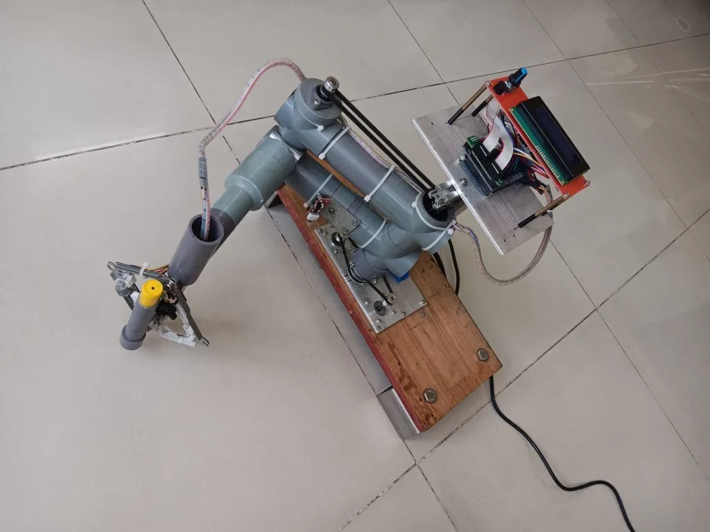
Building your own affordable SCARA plotter with Arduino
Reading Time: 2 minutesRobots come in all shapes and sizes, but one of the most popular styles for industrial applications is the SCARA (Selective Compliance Assembly Robot Arm). These have multiple degrees of freedom, each of which rotates around the vertical Z axis. But they’re otherwise constrained, which can have advantages for certain applications. For…
-

SPIN is a beautiful and imaginative AI synthesizer
Reading Time: 2 minutesIf you’re heard the pop music emanating from any recent reality TV show, you won’t be surprised to learn that AI is perfectly capable of generating tunes on demand. It won’t replace true artistry any time soon, but AI music fits all of the technical criteria. But typing a prompt is boring,…
-

Build a better spindle controller for your CNC mill
Reading Time: 2 minutesProper spindle speed control is necessary to get good CNC milling results. If your spindle speed is inconsistent, your speed and feed calculations will be wrong. That will lead to poor finishes and even broken end mills (and ruined parts) in extreme cases. But cheap CNC mills and routers often have insufficient…
-

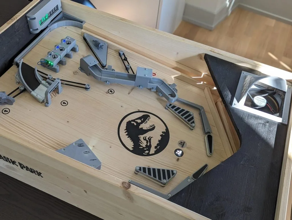
This DIY Jurassic Park pinball machine is a T-Rexcellent use of Arduino
Reading Time: 2 minutesPinball machines are prime examples of the dizzying heights achieved by engineers in the electromechanical era before digital electronics came along. But while those classic pinball machines are extremely impressive from an engineering standpoint, they required an immense amount of expertise and were therefore unapproachable to most. By utilizing modern digital components…
-

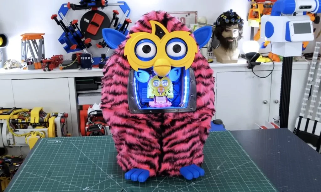
The best Secret Santa gift in an oversized Furby
Reading Time: 2 minutesSome of YouTube’s most famous makers get together every year for a Secret Santa gift exchange. We already showed you the heartbeat-controlled drum machine that Sam Battle created for Ali Spagnola, but what did Battle receive? Roboticist extraordinaire James Bruton drew Battle and decided to build him this oversized robotic Furby. Bruton…
-
A glockenspiel that plays itself
Reading Time: 2 minutesA glockenspiel is a pretty ordinary instrument with a very silly name. Many Westerners will immediately notice the similarities between glockenspiels and xylophones, but there are slight differences in pitch and range. Both are played with mallets and so anyone can hammer out some notes. But playing well is much more difficult,…
-

Macro DLP mirror array scales up a fascinating mechanical structure
Reading Time: 2 minutesDigital light processing (DLP) devices, which we often see in digital projectors, work by reflecting light off of a two-dimensional array of many thousands — or even millions — of moving mirrors. For that to be practical, each mirror must be microscopic and that makes it very difficult to see and understand…
-

Analog gauge array helps evaluate compilation efficiency
Reading Time: 2 minutesThere is an old joke response in the programming industry for whenever you’re caught slacking off: “I’m waiting for the code to compile.” That still holds up, because even today’s blazing fast computers can take ages to compile. That’s true even when the compiler can run tasks across multiple CPU cores. To…
-

TAST-E is an animatronic robot head with a sense of taste and smell
Reading Time: 2 minutesThere are many theories that attempt to explain the uncanny valley, which is a range of humanoid realness that is very disconcerting to people. When something looks almost human, we find it disturbing. That often applies to robots with faces — or robots that are faces, as is the case with the TAST-E robot that has…
-

This RC tank has Möbius strip tracks
Reading Time: 2 minutesMöbius strips are often used to symbolize infinity, because they are continuous loops with only a single surface. They can’t exist in real life, because every solid object in reality has thickness — even if it is very thin, like a piece of paper. But we can construct similar objects that loop and…
-

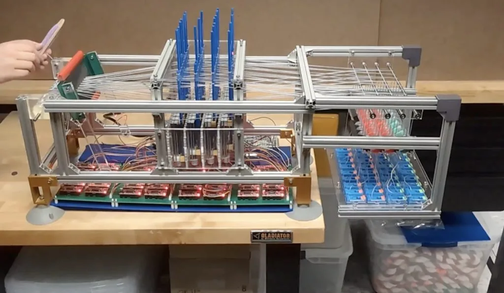
Open-source loom encourages interdisciplinary learning
Reading Time: 2 minutesYou don’t need to go back more than a century to find people who carried the job title “scientist” without any qualifiers. But as STEM fields advanced, people had to become increasingly specialized in more niche disciplines. In recent years, however, we’ve seen a bit of a reversal in that trend and…
-
Replicating Penny’s computer book from Inspector Gadget
Reading Time: 2 minutesThe Inspector Gadget cartoon was, naturally, full of fun gadgets. Even the eponymous inspector’s niece, Penny, got some nifty gizmos. One notable example was her computer book, which was exactly what it sounds like. To pay homage to the classic cartoon, Becky Stern recreated Penny’s computer book using a pair of Arduino boards. It…
-

Building a school bus ride to buy a toddler’s love
Reading Time: 2 minutesWe all know that a child’s love can be bought. But how can working class parents compete with the lavish gifts that wealthy parents can afford? The answer is simple: by building toys that aren’t purchasable. Not only will a DIY gift have far more meaning, but it will impart a sense…
-
Automatic xylophone bings and bongs on demand
Reading Time: 2 minutesXylophones are popular kids’ toys because they’re simple, affordable, and cheery. The name is also fun to say and gives us something to fill in the X spot in alphabet books. But while many of us banged on xylophones as children, few learned how to play them properly. To make such learning…
-

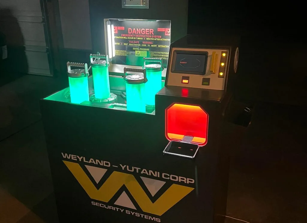
A gorgeous escape room puzzle with an Alien theme
Reading Time: 2 minutesAlien is an icon of the sci-fi horror genre and it owes its status to the legendary design work of H. R. Giger. He was responsible for the very original xenomorph and much of the set design throughout franchise. Alien and its sequels have a distinct visual aesthetic that inspired Redditor Wired_Workshop to build this…
-

This machine automatically threads beautiful string art
Reading Time: 2 minutesString art is impressive precisely because it is so difficult to make. Even a simple piece of string art will contain hundreds of feet of thread carefully looped around posts to create areas of varying density that act as shading. Everything from calculating the string’s path to physically laying down the string…
-

Automating Connect Four setup and cleanup
Reading Time: 2 minutesGood old-fashioned tabletop games are a lot of fun to play, but they’re a pain in the butt to set up. We all know the pain of divvying out Monopoly money and organizing tiny plastic houses. Connect Four players might spend as much time organizing pieces between games as they do actually…
-
Piloting spaceships with a DIY cockpit
Reading Time: 2 minutesTake a moment to go and look up some photos of the cockpits of airplanes and spacecraft. All of them are packed full of instruments and controls. So why do we feel like we can play a flight simulator with a regular gamepad? If you’re doing so, then you’re missing out on…
-

This gargantuan 3D-printed robot hand is just the beginning
Reading Time: 2 minutesIvan Miranda has a humble dream: he wants to build a massive 3D-printed robot that he can ride upon. In other words, he wants a mech. But that is obviously a very challenging project that will take an incredible amount of time and money. So he decided to test the waters with…
-
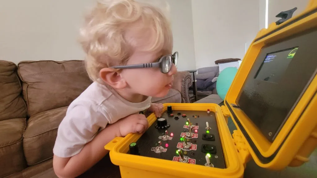
Toddler receives a custom cyberdeck
Reading Time: 2 minutesThe cyberdeck community has exploded in recent years, because makers like to use their creativity to create custom machines tailored to their tastes and requirements. But the community has overlooked one very significant target market: toddlers. Young kids love fiddling with buttons and switches, and there is a plethora of evidence that…
-

James Bruton builds a real Zelda Stabilizer Zonai Device
Reading Time: 2 minutesThe central gimmick of the new Legend of Zelda: Tears of the Kingdom game is the construction system, which is a lot of fun. You can fuse simple objects to build structures, but you can also add Zonai Devices to increase their functionality. One of those devices is the Stabilizer, which forces any attached…