Schlagwort: LED Matrix

  • This gorgeous LED matrix display will wow you

    This gorgeous LED matrix display will wow you

    Reading Time: 2 minutes

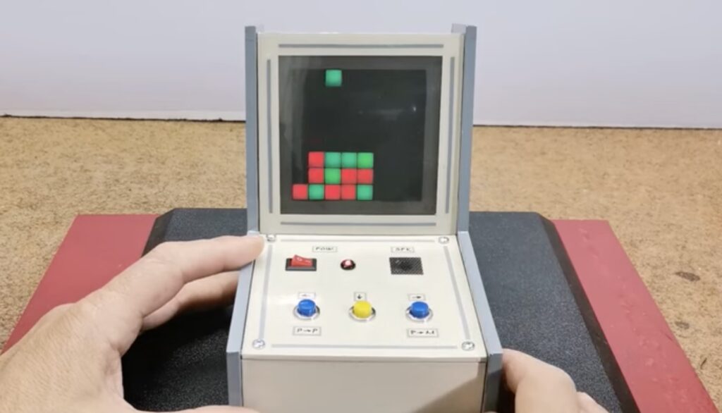
    If you only care about showing content as clearly as possible at the lowest cost, then you’ll want to turn to LCD or OLED technology. But a project’s display gives you an opportunity to get creative with the aesthetic, which opens up a whole world of different display types. If you want a retro feel, then you can inspiration in DIY GUY Chris’ gorgeous LED matrix.

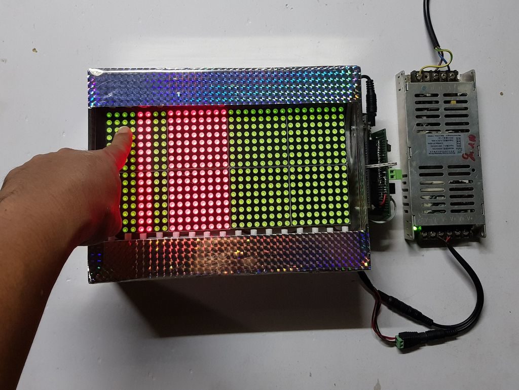
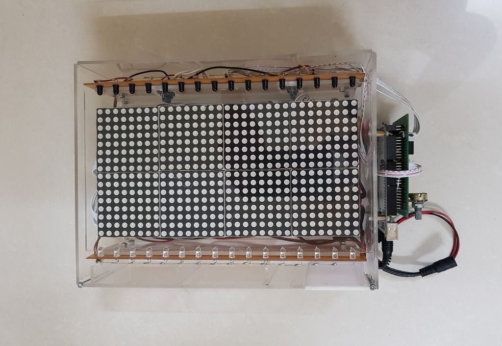
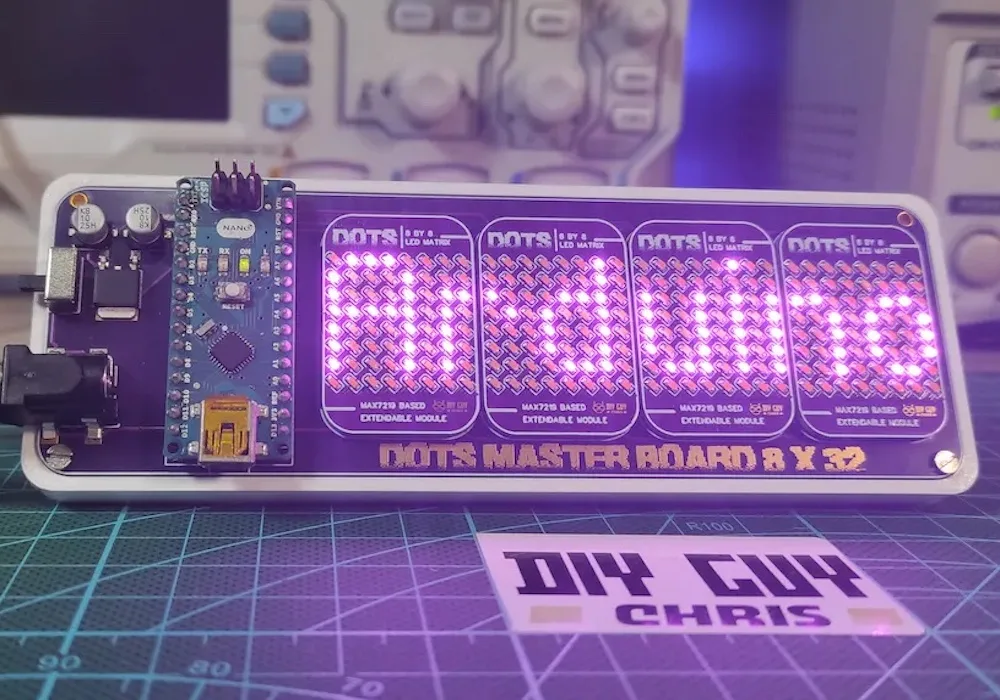
    This is a dot-matrix LED display with an overall resolution of 32×8. But that description alone doesn’t do the project justice. Chris used tiny 0603 SMD LEDs, which allowed for very high “pixel” density and that results in better clarity than a typical LED matrix display. To enable future expansion, Chris set this up as a host board that accepts four LED boards — each of which contains an 8×8 matrix. A MAX7219 IC drives the LEDs on each of those boards.

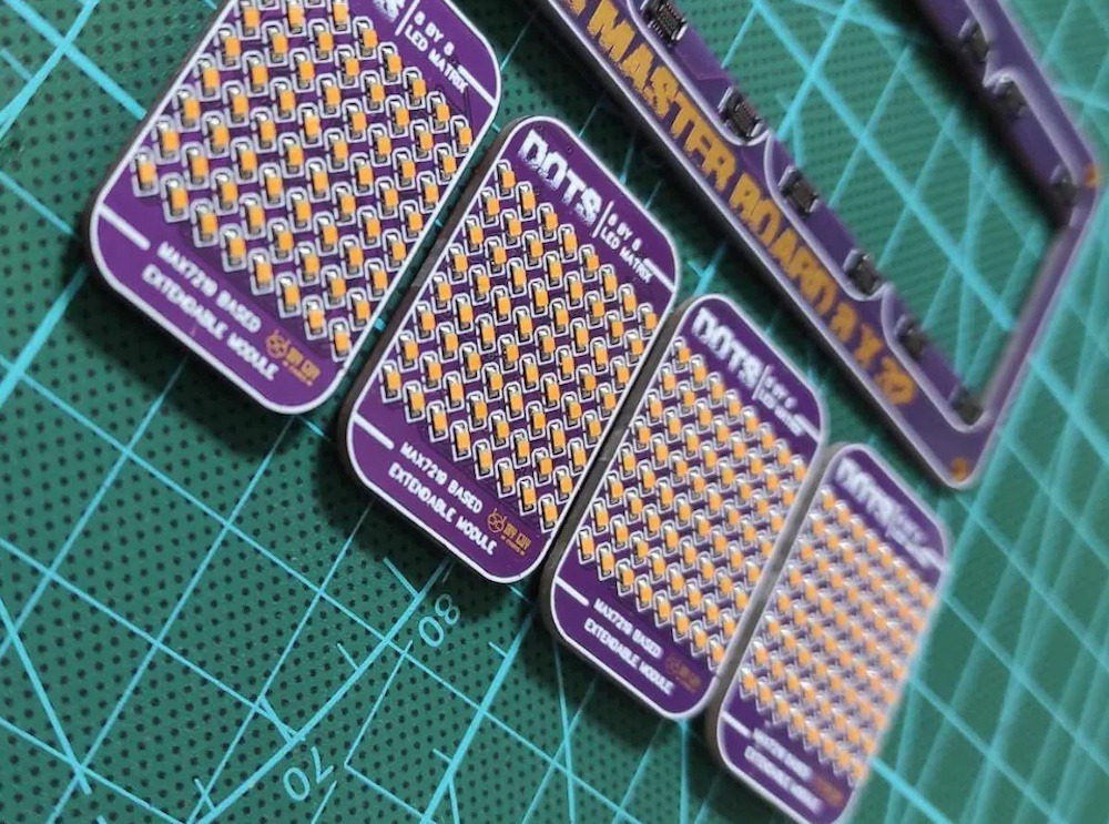
    The LED boards connect to the host board through nifty mezzanine connectors. The host board contains an Arduino Nano that sends control signals to the MAX7219 chips. The Arduino can supply USB power to the LEDs, but there is also a DC jack for power when USB isn’t connected. Chris’ Arduino sketch lets the user “print” alphanumeric characters to scroll across the four LED matrices.

    [youtube https://www.youtube.com/watch?v=b4L3t2bHQ58?feature=oembed&w=500&h=281]

    The best part about this design (other than the great style) is that Chris can scale it up in the future with larger host boards that accept more than four LED boards.

    The post This gorgeous LED matrix display will wow you appeared first on Arduino Blog.

    Website: LINK

  • Electronic game of Connect Four played on an 8×8 LED matrix

    Electronic game of Connect Four played on an 8×8 LED matrix

    Reading Time: 2 minutes

    The childhood classic tabletop game of Connect Four entails dropping either a red or yellow disc into one of several columns in a grid with the hope of lining up four in a row. And even though the game has existed digitally for a while now, it is mostly played on LCD screens with fancier graphics and AIs against which the player competes. Wanting to push this paradigm further, Mirko Pavleski built a mini tabletop arcade cabinet that uses an Arduino Nano and an LED matrix instead to run the game.

    In order to display the current grid to the player(s), Pavleski purchased an 8×8 WS2812B individually addressable LED matrix that gets powered by the Arduino Nano‘s 5V regulator. Because the game can either be played against another human or an AI opponent, the cabinet contains three buttons for selecting the chip’s drop location and a buzzer to deliver audible feedback when an event occurs. The entire device was constructed from a few 5mm PVC boards lined with colored paper for an old-fashioned aesthetic.

    Watching the microcontroller AI opponent play Connect Four in real-time is quite impressive, owing to the relatively small computing resources of the Arduino Nano’s ATmega328 MCU. To see it in action, you can watch Pavleski’s video below or check out his project write-up on Hackster.io.

    [youtube https://www.youtube.com/watch?v=4c123jpPZYk?feature=oembed&w=500&h=281]

    The post Electronic game of Connect Four played on an 8×8 LED matrix appeared first on Arduino Blog.

    Website: LINK

  • LED matrix made touch sensitive with infrared control

    LED matrix made touch sensitive with infrared control

    Reading Time: < 1 minute

    LED matrix made touch sensitive with infrared control

    Arduino TeamAugust 19th, 2019

    If you’d like to integrate touch functionality to your LED project, then tuenhidiy may have just the thing for you

    The setup uses 16 pairs of IR emitter and receivers arranged down the length of a bi-color 16×32 matrix to tell when one has inserted a finger or other object into an area. When sensed, it changes the corresponding column on the display from red to green or back again.

    An Arduino Mega is used for overall control of the device, along with shift registers and multiplexers/demultiplexers to account for the massive amount of IO needed. 

    Code for the build is available on GitHub, and you can see it demonstrated in the video below.

    [youtube https://www.youtube.com/watch?v=wwjCylKhwsw?feature=oembed&w=500&h=281]

    Website: LINK

  • Use an LED matrix as a scanner

    Use an LED matrix as a scanner

    Reading Time: 2 minutes

    Use an LED matrix as a scanner

    Arduino TeamMay 1st, 2019

    Consider that a digital camera uses an array of sensors to capture light from an object. Maker Marcio T, however, decided to turn this idea on its head and instead utilize an array of lights that are detected by a single sensor.

    The way it works is that as each LED in a 32×32 matrix illuminates, a phototransistor picks up light if the path is clear or sees no change if the path is blocked. So when you put an object on the matrix, the sensor is able to get an accurate picture of it, enabling its Arduino Uno controller to then generate its silhouette. 

    It’s a simple yet very clever hack, and if you pay close attention in the video below, you can see the lights scanning from the bottom to top before the image is produced.

    Ordinary digital cameras work by using a large array of light sensors to capture light as it is reflected from an object. In this experiment, I wanted to see whether I could build a backwards camera: instead of having an array of light sensors, I have just a single sensor; but I control each of 1,024 individual light sources in a 32 x 32 LED matrix.

    The way it works is that the Arduino illuminates one LED at a time, while using the analog input to monitor changes in the light sensor. This allows the Arduino to test whether the sensor can “see” a particular LED. This process is repeated for each of the 1,024 individual LEDs rapidly to generate a map of visible pixels.

    If an object is placed between the LED matrix and the sensor, the Arduino is able to capture the silhouette of that object, which is lit up as a “shadow” once the capture is complete.

    [youtube https://www.youtube.com/watch?v=9F9EUaXhj5M?feature=oembed&w=500&h=281]

    Website: LINK

  • Making an LED matrix out of glue sticks

    Making an LED matrix out of glue sticks

    Reading Time: 2 minutes

    Making an LED matrix out of glue sticks

    Arduino TeamJanuary 14th, 2019

    Glue sticks are great for attaching electronics and other bits to projects, but as Jon Bumstead shows in his latest work, they can also make pretty cool light diffusers. 

    His project takes the form of a wooden box with plexiglass panels, allowing observers to see 64 vertical illuminated glue sticks inside. Hidden within the cube are 128 WS2811 LED modules, melted into the top and bottom of each stick. 

    Everything is built around an Arduino Nano, using only a pair of its outputs to control each LED. User interface is provided by a button and knob to adjust speed, color, and patterns.

    In this project, I created a “fiber optic” LED matrix using WS2801 LED strip and glue sticks. The light displays have a different look than similar LED cubes and a few advantages. First, you can’t see the actual LEDs in the display because the glue sticks guide the light away from the LEDs. Second, the device requires much fewer LEDs to make up the volume. Because the top and bottom have different LED strips, the fiber optic cables can take on two different colors that mix in the center. There are tons of different color displays that can be achieved with the device. I also added a button and knob for controlling the speed, color, and type of light display.

    [youtube https://www.youtube.com/watch?v=ZxMkUAYkGSU?feature=oembed&w=500&h=281]

    Website: LINK