Schlagwort: computer vision
-

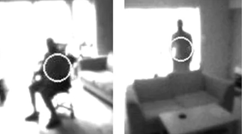
Making a car more secure with the Arduino Nicla Vision
Reading Time: 2 minutesShortly after attending a recent tinyML workshop in Sao Paolo, Brazil, Joao Vitor Freitas da Costa was looking for a way to incorporate some of the technologies and techniques he learned into a useful project. Given that he lives in an area which experiences elevated levels of pickpocketing and automotive theft, he turned…
-

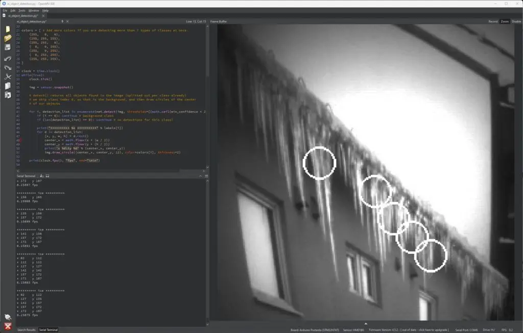
Detecting rooftop ice buildup using an Arduino Portenta and synthetic data
Reading Time: 2 minutesIn areas that experience plenty of cold weather, icicles and ice dams can present a very real danger to the people and property nearby. In response, Eivind Holt has developed a computer vision-based system that relies on an Arduino Portenta H7, a Portenta Vision Shield, and a slew of AI tools/models to recognize this…
-

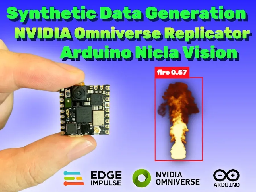
This Nicla Vision-based fire detector was trained entirely on synthetic data
Reading Time: 2 minutesDue to an ever-warming planet thanks to climate change and greatly increasing wildfire chances because of prolonged droughts, being able to quickly detect when a fire has broken out is vital for responding while it’s still in a containable stage. But one major hurdle to collecting machine learning model datasets on these…
-

Intelligently control an HVAC system using the Arduino Nicla Vision
Reading Time: 2 minutesShortly after setting the desired temperature of a room, a building’s HVAC system will engage and work to either raise or lower the ambient temperature to match. While this approach generally works well to control the local environment, the strategy also leads to tremendous wastes of energy since it is unable to…
-

Want to keep accurate inventory? Count containers with the Nicla Vision
Reading Time: 2 minutesMaintaining accurate records for both the quantities and locations of inventory is vital when running any business operations efficiently and at scale. By leveraging new technologies such as AI and computer vision, items in warehouses, store shelves, and even a customer’s hand can be better managed and used to forecast changes demand.…
-

Count elevator passengers with the Nicla Vision and Edge Impulse
Reading Time: 3 minutesModern elevators are powerful, but they still have a payload limit. Most will contain a plaque with the maximum number of passengers (a number based on their average weight with lots of room for error). But nobody has ever read the capacity limit when stepping into an elevator or worried about exceeding…
-

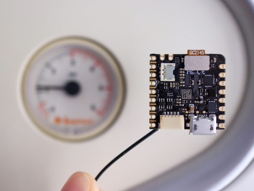
Reading analog gauges with the Nicla Vision
Reading Time: 2 minutesArduino Team — August 13th, 2022 Analog instruments are everywhere and used to measure pressure, temperature, power levels, and much more. Due to the advent of digital sensors, many of these became quickly obsolete, leaving the remaining ones to require either conversions to a digital format or frequent human monitoring. However, the…
-

LEGO-firing turret targets tender tootsies
Reading Time: 2 minutesArduino Team — August 4th, 2022 Stepping on LEGO bricks is a meme for a reason: it really @#$%&! hurts. LEGO brick design is ingenious, but the engineers did not consider the ramifications of their minimalist construction system. We’ve seen people do crazy things for Internet points, such as walk across a…
-

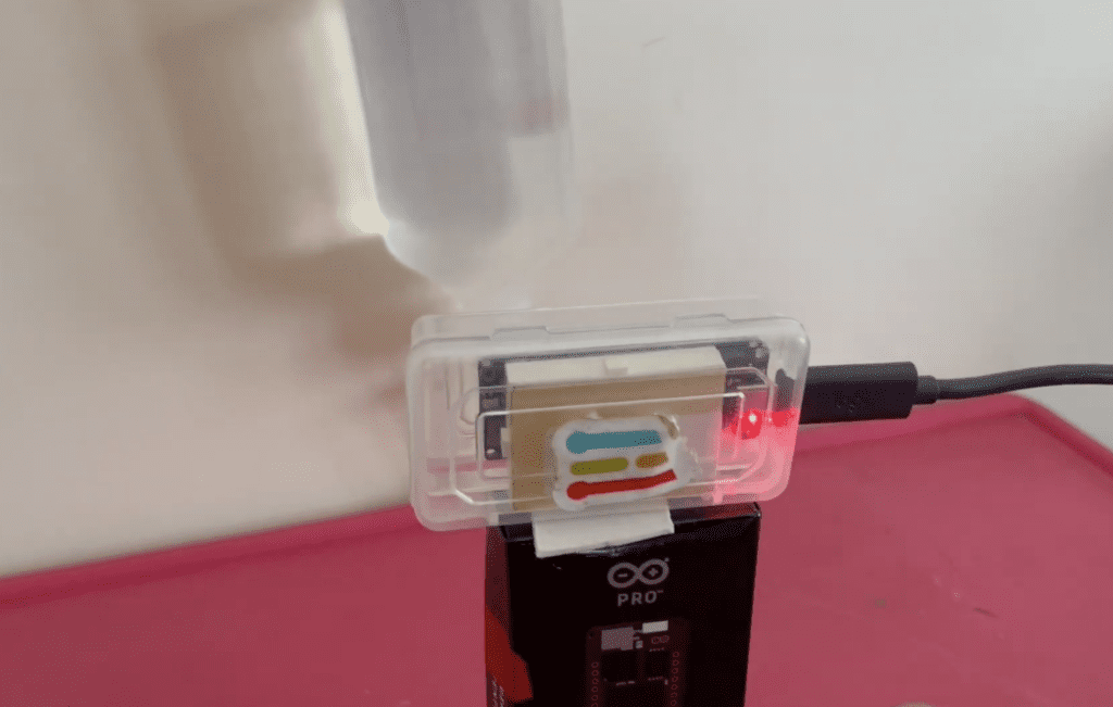
Monitoring IV fluid bag levels with the Arduino Portenta H7 and Vision Shield
Reading Time: 2 minutesArduino Team — June 22nd, 2022 When a patient is receiving intravenous (IV) fluids, it is vital that air is not introduced into the line, as its presence can create issues such as excessive pressure or even embolisms that can be life-threatening. Normally, the level of fluids remaining within the bag is…
-
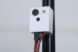
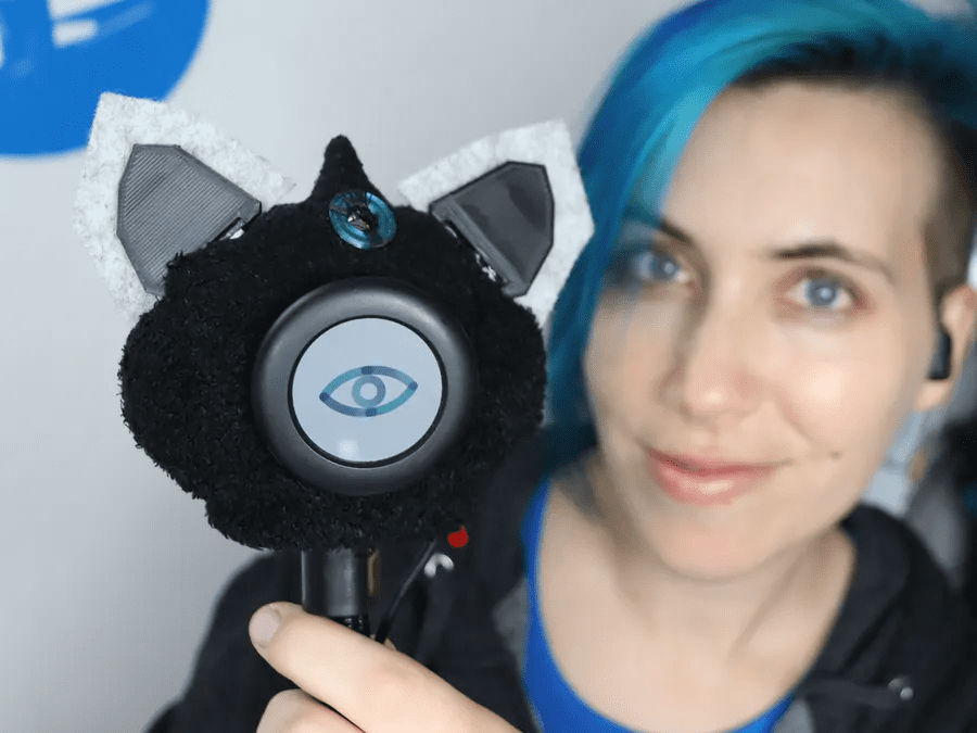
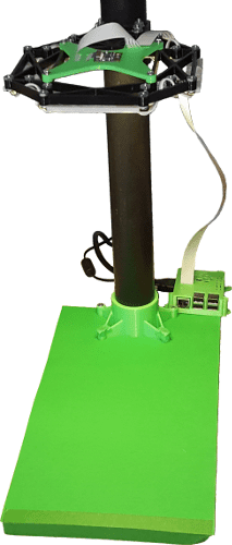
Meet Nikola, a camera-enabled smart companion robot
Reading Time: 2 minutesArduino Team — June 6th, 2022 For this year’s Embedded Vision Summit, Hackster.io’s Alex Glow created a companion robot successor to her previous Archimedes bot called Nikola. This time, the goal was to embed a privacy-focused camera and microphone system as well as several other components that would increase its adorability. The vision system uses…
-

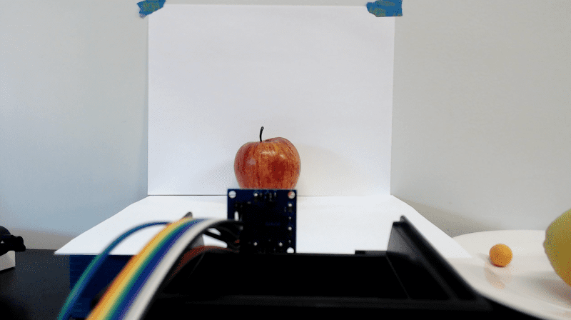
Estimating indoor CO2 levels using tinyML and computer vision
Reading Time: 2 minutesArduino Team — May 6th, 2022 The ongoing COVID-19 pandemic has drawn attention to how clean our indoor environments are, and by measuring the CO2 levels within a room, infection risks can be approximated since more CO2 is correlated with poor ventilation. Software engineer Swapnil Verma had the idea to use computer vision to…
-

This wizard-themed book nook diorama features a face detection system, LEDs, and an ePaper display
Reading Time: 2 minutesArduino Team — October 16th, 2021 The fantastical world of wizards and magic is one that can be explored by reading a book, and what better way to represent this than building your very own interactive diorama within a reading corner? Well, that is exactly what Andy of element14 Presents created when he…
-
Power of Python for Arduino Nano RP2040 Connect and Nano 33 BLE
Reading Time: 3 minutesPython support for three of the hottest Arduino boards out there is now yours. Through our partnership with OpenMV, the Nano RP2040 Connect, Nano 33 BLE and Nano 33 BLE Sense can now be programmed with the popular MicroPython language. Which means you get OpenMV’s powerful computer vision and machine learning capabilities…
-

Optimizing a low-cost camera for machine vision
Reading Time: 15 minutesIn this deep dive article, performance optimization specialist Larry Bank (a.k.a The Performance Whisperer) takes a look at the work he did for the Arduino team on the latest version of the Arduino_OV767x library. Arduino recently announced an update to the Arduino_OV767x camera library that makes it possible to run machine vision…
-

OpenVX API for Raspberry Pi
Reading Time: 3 minutesRaspberry Pi is excited to bring the Khronos OpenVX 1.3 API to our line of single-board computers. Here’s Kiriti Nagesh Gowda, AMD‘s MTS Software Development Engineer, to tell you more. OpenVX for computer vision OpenVX™ is an open, royalty-free API standard for cross-platform acceleration of computer vision applications developed by The Khronos…
-

Machine learning and rock, paper, scissors
Reading Time: 3 minutesUse a Raspberry Pi and a Pi Camera Module to build your own machine learning–powered rock paper scissors game! Rock-Paper-Scissors game using computer vision and machine learning on Raspberry Pi A Rock-Paper-Scissors game using computer vision and machine learning on the Raspberry Pi. Project GitHub page: https://github.com/DrGFreeman/rps-cv PROJECT ORIGIN: This project results from…
-

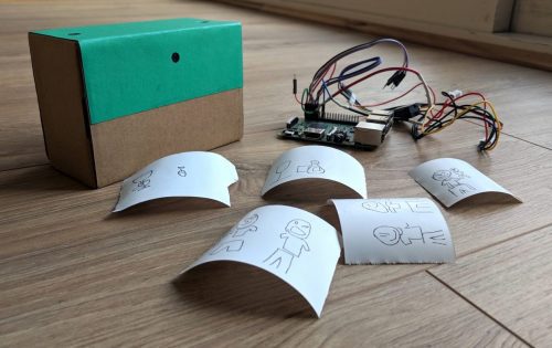
Take a photo of yourself as an unreliable cartoon
Reading Time: 2 minutesTake a selfie, wait for the image to appear, and behold a cartoon version of yourself. Or, at least, behold a cartoon version of whatever the camera thought it saw. Welcome to Draw This by maker Dan Macnish. Dan has made code, instructions, and wiring diagrams available to help you bring this…