Schlagwort: Compute Module 4
-

YouTuber Jeff Geerling reviews Raspberry Pi Compute Module 4
Reading Time: 2 minutesWe love seeing how quickly our community of makers responds when we drop a new product, and one of the fastest off the starting block when we released the new Raspberry Pi Compute Module 4 last week was YouTuber Jeff Geerling. Jeff Geerling We made him keep it a secret until launch…
-

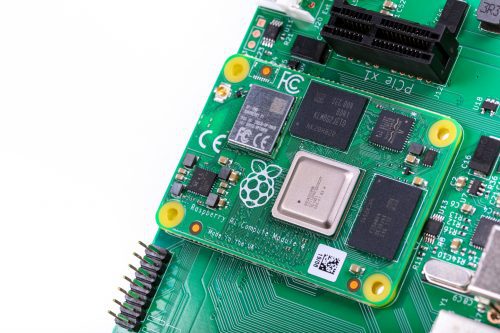
Designing the Raspberry Pi Compute Module 4
Reading Time: 7 minutesRaspberry Pi Compute Module 4 designer Dominic Plunkett was kind enough to let us sit him down for a talk with Eben, before writing up his experience of bringing our latest board to life for today’s blog post. Enjoy. [youtube https://www.youtube.com/watch?v=yiHgmNBOzkc?feature=oembed&w=500&h=281] When I joined Raspberry Pi, James, Eben and Gordon already had…