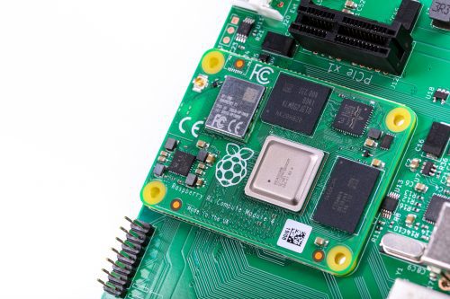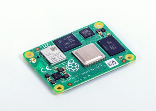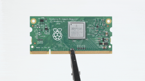
YouTuber Jeff Geerling reviews Raspberry Pi Compute Module 4
Reading Time: 2 minutesWe love seeing how quickly our community of makers responds when we drop a new product, and one of the fastest off the starting block when we released the new Raspberry Pi Compute Module 4 last week was YouTuber Jeff Geerling. Jeff Geerling We made him keep it a secret until launch day after we […]