Schlagwort: arduino
-

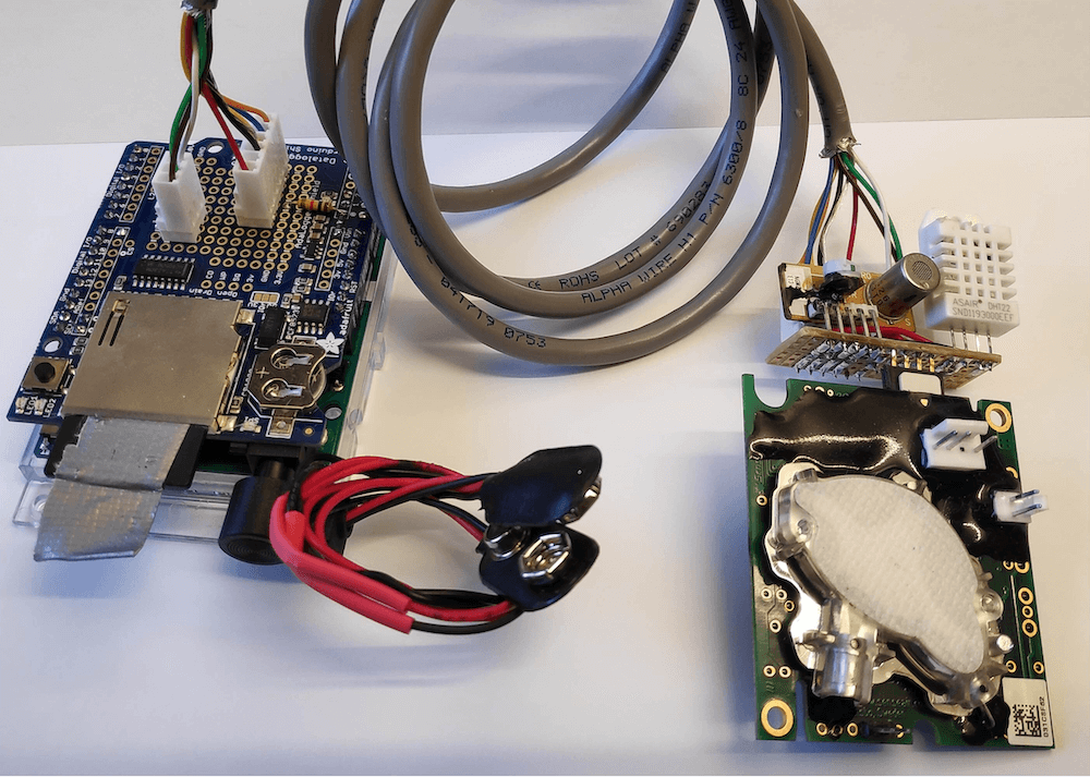
Researchers develop a simple logger for greenhouse gas flows
Reading Time: < 1 minuteResearchers develop a simple logger for greenhouse gas flows Arduino Team — July 28th, 2020 Researchers at Linköping University in Sweden have developed an Arduino-based logger to measure levels of methane and carbon dioxide in greenhouse environments. The device also implements a DHT22 temperature and humidity sensor, data from which can be correlated…
-

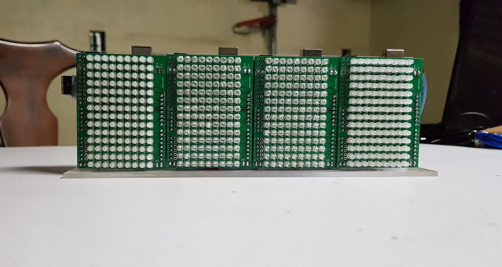
This ‘crazy’ spectrum analyzer visualizes tunes with four Arduinos and 504 LEDs
Reading Time: 2 minutesThis ‘crazy’ spectrum analyzer visualizes tunes with four Arduinos and 504 LEDs Arduino Team — July 26th, 2020 Spectrum analyzers are a great way to visualize music, and “TUENHIDIY” came up with an interesting take on this device using not one, but four Arduino Unos. Each board receives the same sound input via…
-

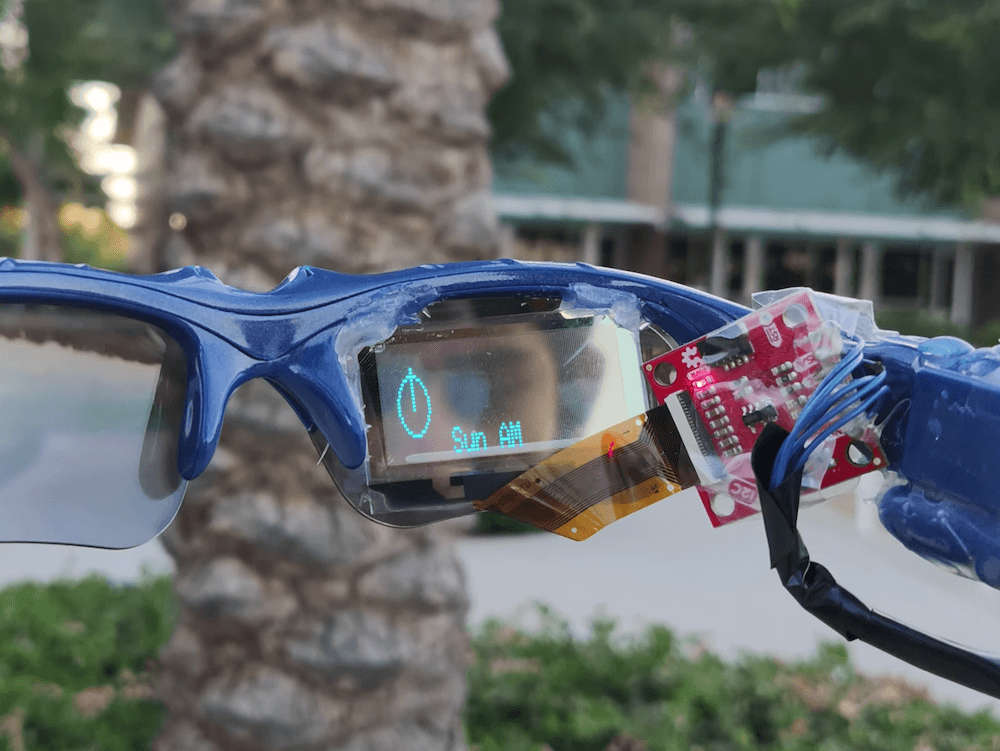
Student designs his own pair of smart glasses with a transparent OLED display and Arduino Nano Every
Reading Time: < 1 minuteStudent designs his own pair of smart glasses with a transparent OLED display and Arduino Nano Every Arduino Team — July 24th, 2020 For his school science fair, Mars Kapadia decided to take things up a notch and create his own pair of smart glasses. The wearable device, which went on to…
-

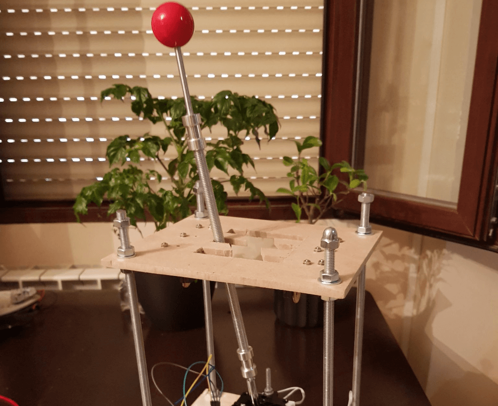
A DIY USB gear stick for PC racing games
Reading Time: < 1 minuteA DIY USB gear stick for PC racing games Arduino Team — July 22nd, 2020 If you’d like to add a gear stick to your virtual race car, then Oli Norwell has just the project for you. His USB device extends a joystick with a length of threaded rod through a…
-

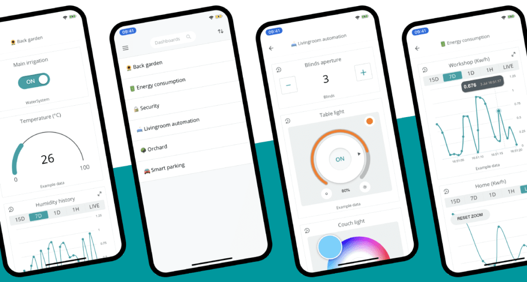
Control your Internet of Things projects from anywhere with the new Arduino IoT Cloud Remote app
Reading Time: 2 minutesControl your Internet of Things projects from anywhere with the new Arduino IoT Cloud Remote app Arduino Team — July 22nd, 2020 The perfect companion to the Arduino IoT Cloud! Develop your IoT solution online via a desktop, then monitor and control your dashboards on your mobile with the new Arduino IoT…
-

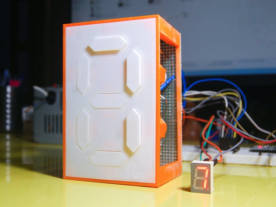
Mechanical 7-segment display made using electromagnets
Reading Time: < 1 minuteMechanical 7-segment display made using electromagnets Arduino Team — July 21st, 2020 When you think of a “7-segment” display, your mind naturally goes to something involving LCD or LED technology. As seen here, however, this 0-9 pattern can also be duplicated mechanically using a series of electromagnets. Neeraj Rane’s 3D-printed device is…
-

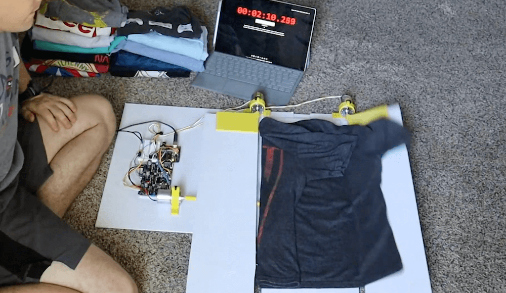
This Arduino-powered machine folds your shirts at the push of a button
Reading Time: < 1 minuteThis Arduino-powered machine folds your shirts at the push of a button Arduino Team — July 21st, 2020 Inspired by an old FlipFold TV ad, YouTuber Ty Palowski decided to make his own automated shirt folding machine. Palowski’s device is made in four folding sections, which lie flat to accept the…
-

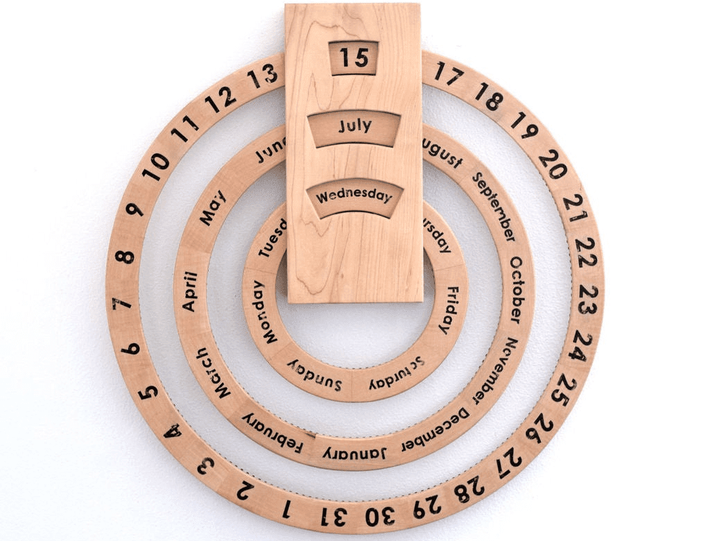
This automated perpetual calendar is a beautiful way to watch the years pass by
Reading Time: 2 minutesThis automated perpetual calendar is a beautiful way to watch the years pass by Arduino Team — July 20th, 2020 Troy Hawkins (AKA “tomatoskins”) had come across an interesting wooden perpetual calendar, which used a trio of rings to show the month, day, and day of the week. The only problem is…
-

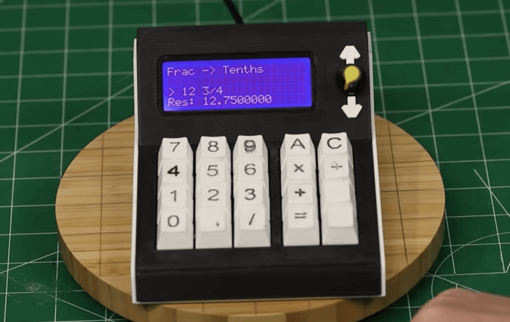
Creating a convenient calculator for unit conversions
Reading Time: < 1 minuteCreating a convenient calculator for unit conversions Arduino Team — July 19th, 2020 Whether you work in meters, feet, inches, or kilometers — or any number of other units corresponding to properties that you need to convey — conversions are a fact of life when making things. While this could mean…
-

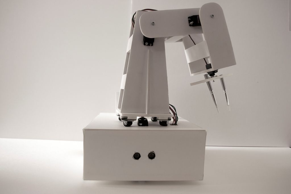
Painting robot with ‘twin’ control scheme
Reading Time: 2 minutesPainting robot with ‘twin’ control scheme Arduino Team — July 16th, 2020 For a class project, University of Stuttgart students Ekin Sila Sahin, Lior Skoury, and Simon Treml came up with a unique painting robot named the Physical Twin. The Physical Twin travels on a three-wheeled chassis and mounts a four-axis arm with a…
-

A hand-following AI task lamp for your desk
Reading Time: < 1 minuteA hand-following AI task lamp for your desk Arduino Team — July 15th, 2020 As you work on a project, lighting needs change dynamically. This can mean manual adjustment after manual adjustment, making do with generalized lighting, or having a helper hold a flashlight. Harry Gao, however, has a different solution…
-

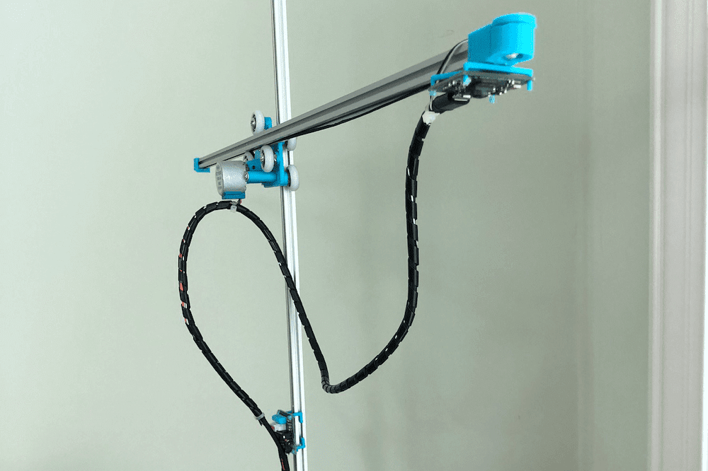
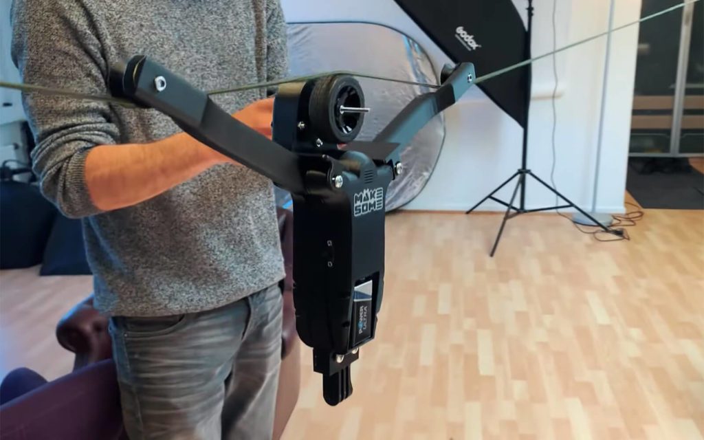
DIY cable cam made from RC car and 3D-printed parts
Reading Time: < 1 minuteDIY cable cam made from RC car and 3D-printed parts Arduino Team — July 14th, 2020 Cable-mounted cameras can be a lot of fun for capturing moving footage. Although commercial cable cam options can be expensive, this system by Kasper Mortensen of MAKESOME is comprised of 3D-printed components with a receiver and…
-

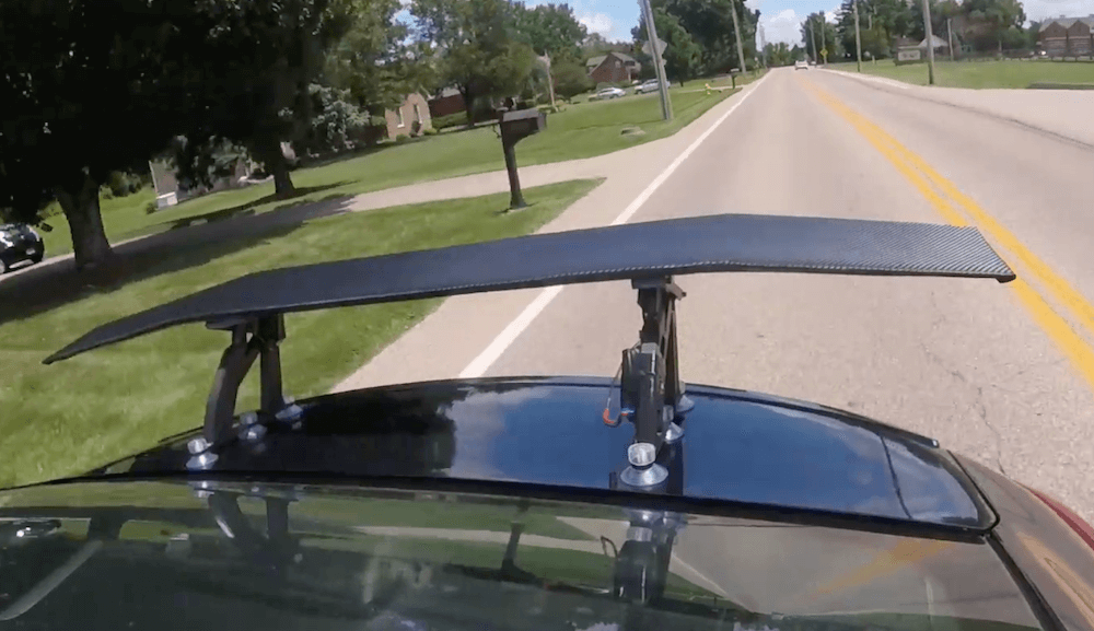
Deck out your ride with an Arduino-controlled spoiler
Reading Time: < 1 minuteDeck out your ride with an Arduino-controlled spoiler Arduino Team — July 14th, 2020 Car spoilers can provide downforce for better performance, or simply give the appearance of speed. To take things to another level, Michael Rechtin designed his own custom wing that doesn’t just sit there, but pitches up and…
-

The MemGlove detects hand poses and recognizes objects
Reading Time: 2 minutesThe MemGlove detects hand poses and recognizes objects Arduino Team — July 14th, 2020 Hand movements have long been used as a computer interface method, but as reported here, the MemGlove from a team of MIT CSAIL researchers takes things several steps further. This augmented glove can sense hand poses and how it’s applying…
-

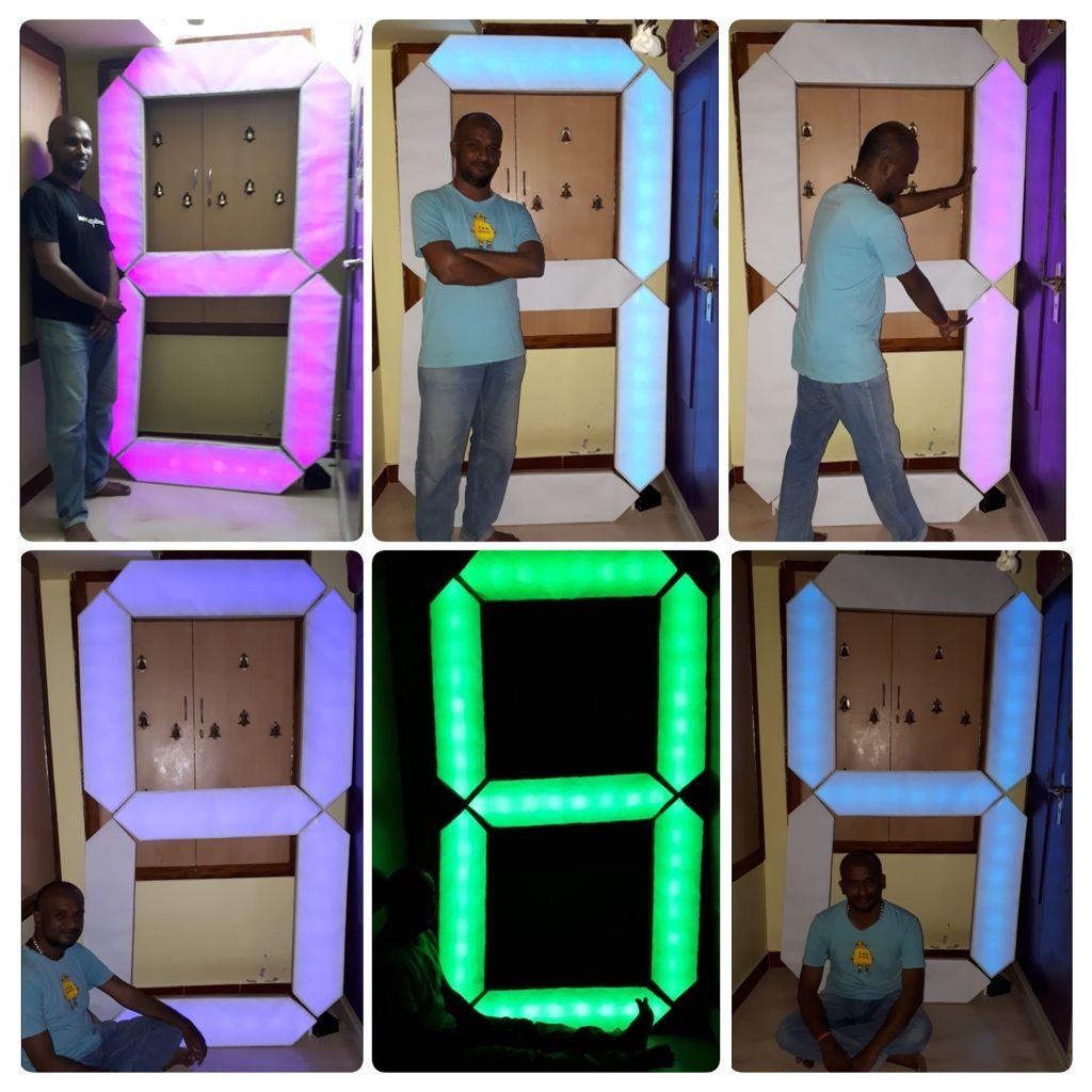
A 7-foot-tall 7-segment display
Reading Time: 2 minutesSeven-segment displays are normally diminutive items, able to show info from a clock or other device, in a size that’s easily tucked away when not needed. Jegatheesan Soundarapandian’s single-digit display, however, is just the opposite standing at nearly seven feet tall. The project is constructed out of cardboard, with a PVC spine for…
-

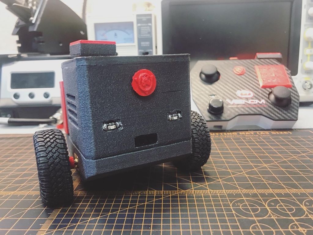
Meet MrK_Blockvader, a little mobile robot that’s lots of fun
Reading Time: < 1 minuteOne of the simplest ways to make a mobile robot involves differential steering, where two wheels move at different speeds as needed to turn and a ball caster keeps it from tipping over. The MrK_Blockvader is an excellent take on this type of bot — demonstrated in the first clip below — featuring…
-

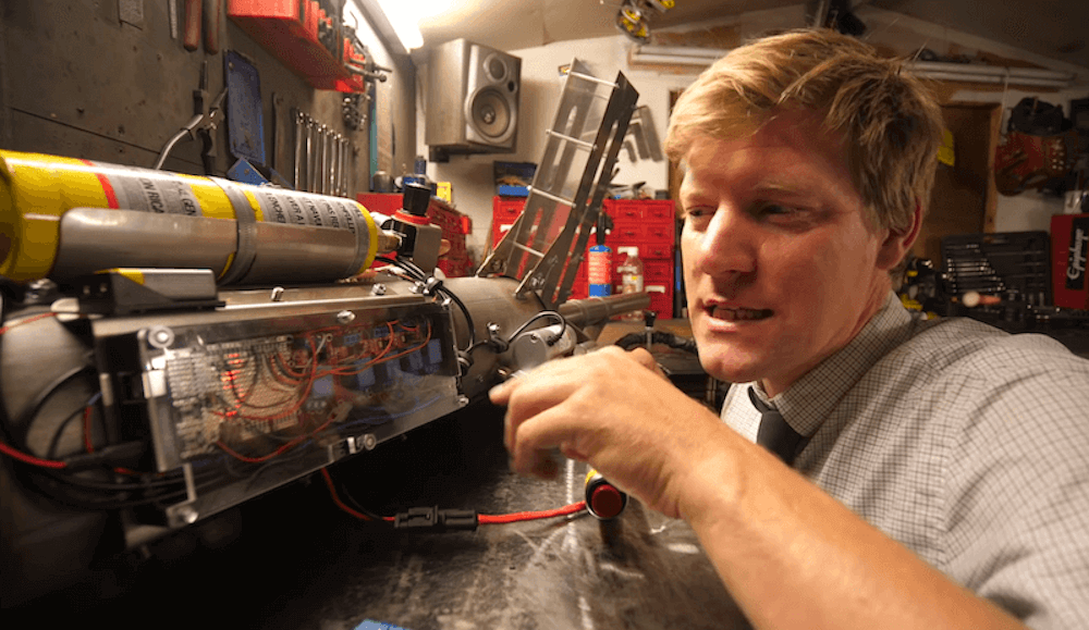
Don’t try this at home: Colin Furze creates a semi-automatic potato cannon
Reading Time: < 1 minuteDon’t try this at home: Colin Furze creates a semi-automatic potato cannon Arduino Team — July 9th, 2020 Colin Furze decided that he needed a potato cannon for his DIY screw tank, and after making a manually loaded version, he automated the process. What he came up with uses a pair of…
-

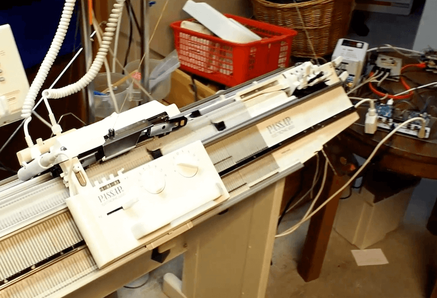
Rebuilding a Passap E6000 knitting machine with Arduino and Raspberry Pi
Reading Time: 2 minutesRebuilding a Passap E6000 knitting machine with Arduino and Raspberry Pi Arduino Team — July 8th, 2020 Irene Wolf is the owner a Passap E6000, a computerized knitting machine which features pair of needle beds, and decided it was time to give it an upgrade. In particular, she wanted the ability to…
-

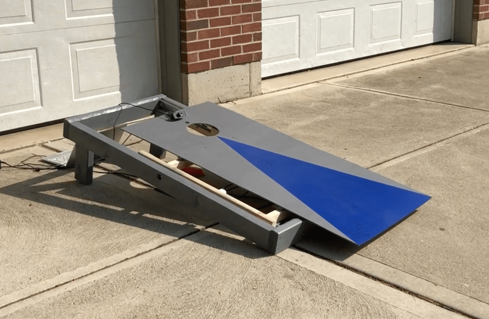
Robotic cornhole board guarantees three points every time
Reading Time: < 1 minuteRobotic cornhole board guarantees three points every time Arduino Team — July 8th, 2020 You may have seen Mark Rober’s automated dartboard or Stuff Made Here’s backboard, which use advanced engineering to create apparatuses that ensure you “can’t miss.” Now that summer is in full swing, what about a robotic cornhole board?…
-

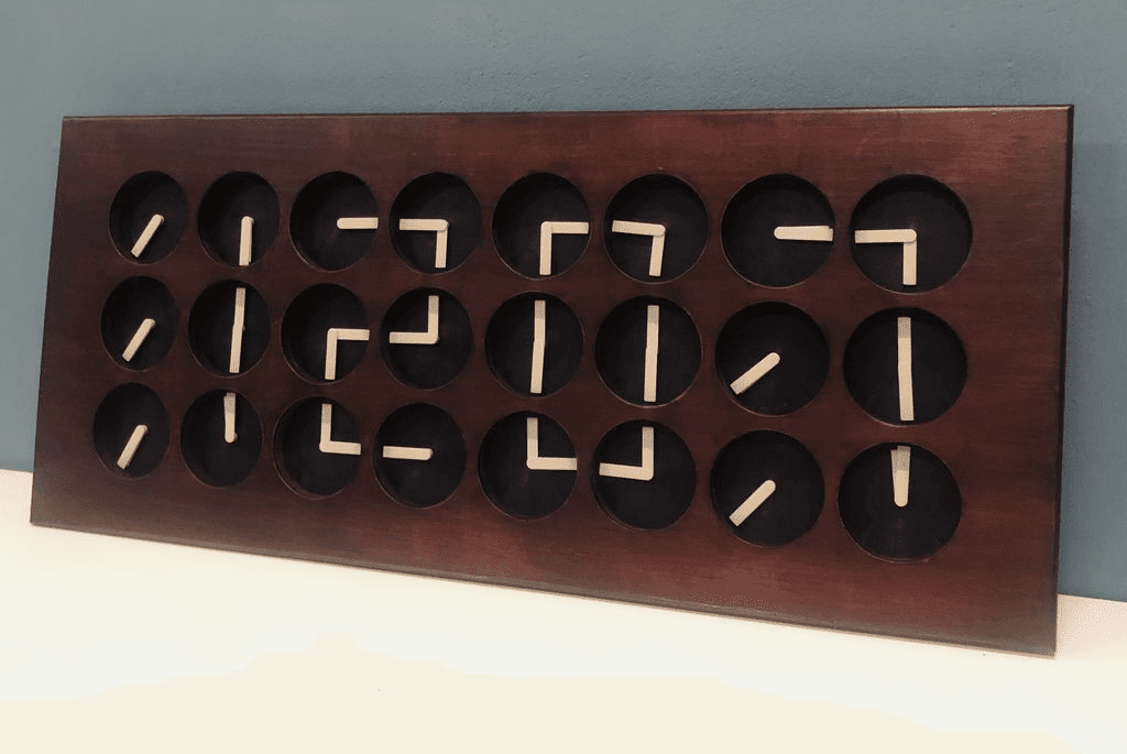
Create a digital clock out of 24 analog clocks
Reading Time: < 1 minuteCreate a digital clock out of 24 analog clocks Arduino Team — July 7th, 2020 What if you were to use the hands of a clock not as an individual display, but as part of an array that moves together to form digits? That’s the idea behind Clockception by “Made by Morgan,” which…
-

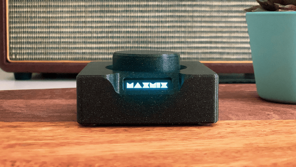
Change the volume of any app on your PC with the turn of a knob
Reading Time: 2 minutesChange the volume of any app on your PC with the turn of a knob Arduino Team — July 7th, 2020 Overall computer volume control is important, but what if you want to get more granular, adjusting sound from various applications individually? Rather than going through a series of menus and on-screen…
-

Build a comment-critiquing keyboard adapter using TensorFlow Lite and Arduino
Reading Time: 2 minutesBuild a comment-critiquing keyboard adapter using TensorFlow Lite and Arduino Arduino Team — July 7th, 2020 If you’ve ever left an online comment that you later regretted, this anti-troll bot will keep that from happening again by letting you know when you’re being a bit too harsh. The device — which was…