Schlagwort: arduino

  • Using historical data from sensors in Arduino Cloud

    Using historical data from sensors in Arduino Cloud

    Reading Time: 4 minutes

    Historical data can be essential to making your electronics and Arduino project work how you want them to. Data retention is one of the features that changes depending on which level of Arduino Cloud account you have. Here’s everything you need to know, so you can choose exactly the right Arduino Cloud plan.

    Data or Variables?

    When you add variables to your Things, the Arduino Cloud automatically generates sketches that include them.

    Hang on though. Aren’t we here to talk about data retention?

    Indeed we are. When we say “variables”, this is the term used to describe the data you send to your Arduino Cloud. It sounds a bit technical, but consider the word. “Variable” actually makes more sense than “data”, which is kinda woolly.

    Variables are information that changes or, you guessed it, varies. Temperature, for example. If you have a temperature sensor sending data to the Cloud, it’s a variable. Because the value of the data (the temperature) is always changing/varying. 

    So in your sketch it’s known as a variable. The different data retention options in the Arduino Cloud plans tell you how long the Cloud will store a record of those variables for you.

    Data retention options in Arduino Cloud

    Historical Data Options

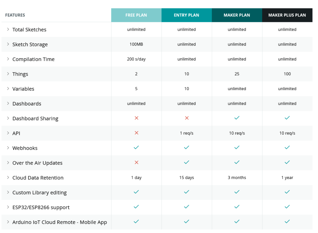
    Each Arduino Cloud plan offers a different length of time for how long you retain sensor data, depending on your needs.

    If you’re running a home automation to turn the lights on when it drops dark, your system is working with (pretty much) real-time data. So 24 hours of sensor information is perfectly adequate. It’s not like you’ll be turning a lamp on or off based on yesterday’s ambient light levels.

    A weather station might work a bit differently though. If you’re measuring the temperature or rainfall or daylight hours, you may want to build a comparison to see how the weather is changing. In this case, an Arduino Cloud Entry plan would give you 15 days of data, allowing you to monitor and record recent changes in your weather station’s variables.

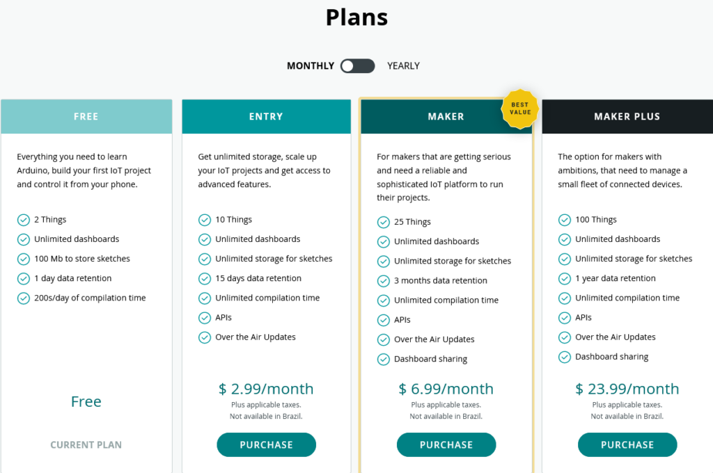
    Historical data for an IoT greenhouse, or maybe an aquarium or terrarium, would be much more important. Maybe it’s even an industrial project that’s monitoring equipment for predictive maintenance needs. In these cases, being able to look back at your variables over previous weeks and months could be essential. In that case, you’d go Maker or Maker Plus, so you can build dashboards with detailed histories of your measurements.

    It’s very possible that you don’t even know how much historical data will be useful to your project at first. You start on the free tier, decide that it’d be useful to have legacy information, and go up through the Entry plan and eventually settle on Maker. The project leads the way, until it’s delivering everything you need.

    Historical data in your Arduino Cloud

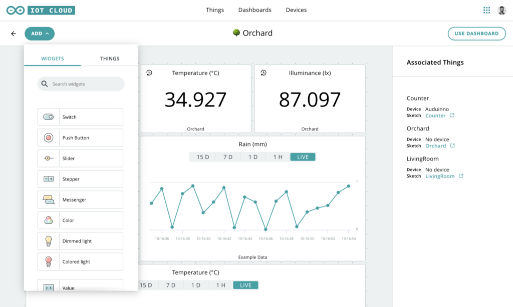
    Putting Historical Data to Use in Arduino Cloud

    Arduino Cloud is really clever when it comes to the data generated by sensors and used as variables. For example, you can specify how often new data is sent to your Arduino Cloud.

    Let’s say you’re monitoring Wi-Fi signal strength at the bottom of the garden, where a project (weather station, let’s say) is installed. If this is a solar and/or battery powered device, power consumption becomes essential. By changing the data sampling interval from updating a variable on Arduino Cloud every second to updating once a minute, you can extend battery life by a huge amount. The device is only operating a fraction of the time it was before, and the information is just as useful.

    Combined with 15 days or three months of historical data, you can build a detailed picture of Wi-Fi performance that lets you keep everything running perfectly. Or, if you need to find out when and why your signal has been dropping, the story is right there in your Arduino Cloud dashboard.

    Choosing the Right Arduino Cloud Plan

    So for all these reasons, you can see why different amounts of data retention are available in the Arduino Cloud plans. It’s not that all projects benefit from as much retention as possible. As we discussed, even some complex, elaborate projects barely need any. Others, which might be simple signal strength monitoring or rainfall measurement, need to know what was happening months ago.

    You have the choice, because the different Arduino Cloud plans offer different historical data options for different needs. If in doubt for what your project needs to work as intended, start on the free plan and work up from there.

    Choose Arduino Cloud Plan

    Website: LINK

  • Recreating an old-school mechanical split-flap display with Arduino

    Recreating an old-school mechanical split-flap display with Arduino

    Reading Time: 2 minutes

    Arduino TeamJuly 1st, 2021

    Those old-school split-flap character displays are super fun to look at, not to mention listen as well from the click each time a letter changes. Sadly, these have largely been replaced by more modern and efficient LED screens, leaving those who love the tactile feel a little on their own. Thankfully, Dave Madison has created a DIY version that supports 40 total characters per digit with eight digits total. 

    The whole thing is housed inside a laser-cut acrylic enclosure, with each digit module consisting of a single stepper motor, a wheel with cutouts for 40 pins, and the roll of split cards. Madison was able to generate 39 different characters ranging from the 26 letters, 10 digits, and three extra punctuation marks onto a piece of vinyl which he then cut out and glued onto the cards.

    In terms of electronics, the system uses a custom-designed PCB that packs four status LEDs, a shift register, stepper motor drivers, and headers for inputs and outputs. An Arduino Nano runs the firmware that takes in characters from the serial terminal and converts them into split card movements using some clever math. 

    In the future Madison plans to add the capability for WiFi control along with a web server. But even now the project looks great, and you can read more about it here in its write-up.

    [youtube https://www.youtube.com/watch?v=4hwadqDmcfY?feature=oembed&w=500&h=281]

    Website: LINK

  • This low-cost device uses tinyML on Arduino to detect respiratory diseases in pigs

    This low-cost device uses tinyML on Arduino to detect respiratory diseases in pigs

    Reading Time: 2 minutes

    Arduino TeamJune 30th, 2021

    One major drawback to the largescale farming of animals for meat consumption is the tendency for diseases to spread rapidly and decimate the population. This widespread issue is what drove Clinton Oduor to build a tinyML-powered device that can perform precision livestock farming tasks intelligently. His project works by continuously monitoring the noise coming from pigs and makes a determination about what they mean, such as if a cough is indicative of a respiratory illness or a squeal denoting stress. 

    Oduor gathered the sound samples for his dataset by downloading around seven minutes of coughing pig sounds and then split them up into one-second-long files. After using a trick called data curation that allows for more samples to be generated from previous ones, he trained a neural network with Edge Impulse and was able to achieve a 99.7% accuracy. As for deployment, the model runs on an Arduino Nano 33 BLE Sense, which has an onboard microphone for picking up ambient sounds. When coughing is detected, it sends some data via I2C to a MKR FOX 1200 board that broadcasts a message over the Sigfox network. 

    The developer plans on collecting more data from various pig species and at different stages of growth to further enhance the diversity of the model and increase its accuracy. As a more advanced challenge, he would also like to have his device recognize specific cough patterns for certain types of respiratory diseases. You can read more about his project here.

    Website: LINK

  • ZARDOS, Ze ARDuino Operating System

    ZARDOS, Ze ARDuino Operating System

    Reading Time: 2 minutes

    Arduino TeamJune 30th, 2021

    Operating systems are pieces of software that control hardware and software systems within a computer to allow for task scheduling, resource management, and concurrency. Popular OSes included Windows, macOS, GNU/Linux, and Raspbian, but all of these are incapable of running on extremely small processors such as the ATmega328P. That is where ZARDOS, which stands for “Ze ARDuino Operating System,” can help. It is an OS that runs primarily on the Arduino Mega, although its creator says a minimum version can also run on the Arduino Uno

    At the most basic level, ZARDOS communicates with a Minitel 1B or 2 terminal over a single DIN-5 cable via a serial link. Once running, the Arduino board can read in and execute new software via a “cartridge” system, as well as host a filesystem on an SD card. The OS also lets users add a PS-2 mouse, speaker, and videotex printer, which means this device is quite the throwback to the earlier days of home computing. 

    ZARDOS is a very impressive pieces of software for the Mega, and it will be exciting to see just how far this project goes in the future. To learn more, check out its site here.

    Website: LINK

  • EduExo Pro is an Arduino-controlled robotic exoskeleton kit that’s now on Kickstarter

    EduExo Pro is an Arduino-controlled robotic exoskeleton kit that’s now on Kickstarter

    Reading Time: 2 minutes

    EduExo Pro is an Arduino-controlled robotic exoskeleton kit that’s now on Kickstarter

    Arduino TeamJune 29th, 2021

    Admit it, you have dreamed of wearing something like Tony Stark’s Iron Man suit. Sadly, that technology is fictional and real world exoskeleton suits are expensive. But a Swiss company called Auxivo wants to make exoskeletons available to educators, students, and hobbyists. To make that happen, they’re releasing their new EduExo Pro wearable robotic exoskeleton kit.

    The EduExo Pro is available on Kickstarter to backers in a variety of packages, from a DIY version to a complete, assembled arm. Whichever option you choose, you will end up with a robotic exoskeleton arm that straps onto your own arm to enhance your strength. It has steel load-bearing structural parts and ball bearings on the joints. The shoulder joint has a heavy spring to provide assistance, while the elbow joint utilizes a powerful stepper motor.

    An Arduino Uno board controls the stepper motor. It receives data from two sensors: a potentiometer to detect the elbow joint angle and an EMG (electromyography) sensor to monitor bicep muscle activity. The latter can detect when the wearer is flexing their bicep and then push power to the stepper motor. The arm also interacts with software running on a connected computer. For example, the EduExo Pro handbook provides instructions for integrating the arm with a Unity3D virtual reality game.

    If you’re interested in trying the EduExo Pro for yourself, the Kickstarter campaign is running until July 29th.  

    Website: LINK

  • DIY radar speed sign looks and works like the real thing

    DIY radar speed sign looks and works like the real thing

    Reading Time: 2 minutes

    Arduino TeamJune 29th, 2021

    Those large, white speed signs you encounter alongside the road while driving can be annoying, as inattentive drivers slam their brakes right in front of you. However, the underlying technology that powers them is quite cool, which is why John McNelly wanted to construct his own DIY version that closely reflects the actual one. 

    McNelly’s design relies on an Arduino Nano and a Doppler radar module that sends out 10.525GHz radio pulses continuously and measures how much the reflected frequency has changed. Thinking back to that one high school physics class, you probably learned that as an object approaches, the reflected frequency will increase, whereas the frequency will decrease as the object gets further away. Using the Doppler effect, speed can be determined by subtracting the frequency coming from a custom pre-amplifier from the original signal. 

    The sign also uses a giant seven-segment display for showing the speed to passersby. Because using fourteen very bright LEDs is quite inefficient, McNelly opted to design and assemble his own PCBs that each hold eighteen amber LEDs, and all of the segments are controlled by a SPI shift register — one for each digit. 

    You can see from his video below that the sign is very similar to its real counterpart, as the digits are bright and the speed is measured accurately. For more details on the project, check out McNelly’s website and the code and design files on GitHub.

    [youtube https://www.youtube.com/watch?v=Z29-ef3O5mM?feature=oembed&w=500&h=281]

    Website: LINK

  • This MKR Zero system gives early warning of potential sump pump problems

    This MKR Zero system gives early warning of potential sump pump problems

    Reading Time: 2 minutes

    Arduino TeamJune 29th, 2021

    As most homeowners with a basement will tell you, keeping track of the sump pump is an important part of maintenance, as neglecting it can lead to the basement turning into a swimming pool. This is the exact predicament that a recent element14 Build Inside the Box winner, Mike Moore, ran into with his house because freezing pipes and an unreliable pump often became problematic. He went with multiple approaches to solve this, including water level detection, temperature monitoring, and even checking if the pump has ceased working. 

    The first component used was a TCST1103 photo interrupter, and its job is to send a signal if a bobbing piece of plastic gets between its emitter and receiver, which would indicate the water level has risen too high. For more granular and continuous measurements, Moore also implemented a VL53L0X time-of-flight sensor that sends a laser beam towards the water and waits for a reflection. Because water can distort this reading, a couple of readings get taken and then averaged together. Temperatures are read by a simple MCP9701 IC that was placed inside of a plastic tube and stuck to the side of the pit. Finally, detecting if the pump is running is handled by an MCP604 IC. 

    All these sensors are controlled with an Arduino MKR Zero that can sound an alarm if something’s wrong, and power is provided via a portable high-capacity battery bank. In the future, Moore plans to add SD card logging so he can view long-term trends in the data readings.

    To see more about his project, you can view the element14 Presents video below and check out Moore’s write-up here.

    [youtube https://www.youtube.com/watch?v=0-mAIYFYO7k?feature=oembed&w=500&h=281]

    Website: LINK

  • Use tinyML on the Nano 33 BLE Sense to classify different bird calls

    Use tinyML on the Nano 33 BLE Sense to classify different bird calls

    Reading Time: 2 minutes

    Arduino TeamJune 28th, 2021

    There are thousands of bird species in the world, with numerous different and unique ones living in various areas. Developers Errol Joshua, Mahesh Nayak, Ajith K J, and Supriya Nickam wanted to build a simple device that would allow them to automatically recognize the feathered friends near them and do some simple tracking, such as knowing how often a particular bird makes its call. Their project uses a Nano 33 BLE Sense, along with its onboard microphone, to pick up sounds and make inferences about what they are in real-time. 

    The team decided to train their tinyML model to detect four different species that are native to their area and then downloaded a sample dataset containing many sound files. After a bit of editing, they transferred the audio clips into Edge Impulse’s Studio and subsequently labeled each one. The Impulse consisted of a Mel-filter-bank energy (MFE) block that took the sounds and produced a spectrogram for each one. With these processed features, the model was able to achieve an impressive 95.9% accuracy. 

    As seen in their demonstration video below, the current bird sound being played was picked up and identified accurately by the Nano 33 BLE Sense. And with some minor changes to how the model was trained, the accuracy can be increased even more. You can read about this project on its page.

    [youtube https://www.youtube.com/watch?v=g_WQIHfQb8E?feature=oembed&w=500&h=281]

    Website: LINK

  • The MonKlock tells time using the Cistercian numeral system

    The MonKlock tells time using the Cistercian numeral system

    Reading Time: 2 minutes

    Arduino TeamJune 25th, 2021

    Way back in the 13th century, an order of monks known as the Cistercians created a unique numbering system that used a series figures and rotations to represent numbers up to 9,999 in just a single character. Because these numerals are so great in compact displays, using them in a dot matrix to show the current date and time was a no-brainer for danjovic.

    For the aptly named MonKlock, Danjovic combined a DS3231 real-time clock with an Arduino Nano to keep track of the current time, plus a large 4″ 5×7 LED matrix. All of these components were placed onto a custom PCB, along with two buttons that cycle between various modes and the time, day, month, and year. Finally, he made a wooden base that props up the PCB vertically and provides a convenient path to run the USB cable. 

    In order to translate a given decimal number into a Cistercian numeral, danjovic designed a custom font that maps the figure to an array of pixels. When it’s time to display a number, the required numerals are added on top of each other using some simple arithmetic, and then the final result is sent to the LED matrix. 

    As seen in Danjovic’s video below, the clock looks really cool while powered on, and the additional functionality from the two buttons adds even more fun. Even though it can take a while to learn what each numeral represents, this project is still a great showcase of using clever math to fit dense information in a small space. 

    [youtube https://www.youtube.com/watch?v=8cjMaMe3Ewg?feature=oembed&w=500&h=281]

    Website: LINK

  • Private Sketches for Arduino Cloud

    Private Sketches for Arduino Cloud

    Reading Time: 3 minutes
    Private sketches on Arduino Cloud

    Private sketches are now available as part of your Arduino Cloud. It’s a new option that provides you with more control over how you share sketches, and who can view them.

    Sharing Sketches From Arduino Cloud

    As you probably already know, you can easily share sketches that you’ve created in your Arduino Cloud. This includes auto generated IoT Cloud sketches as you add new devices and variables.

    It’s a great feature that gives you a lot of options for working directly from your Arduino Cloud. The community is all about open-source, and sharing is a big part of that. 

    You might want to let other developers use and improve on your sketches. Or Maybe you want to make it public so you can get support or advice.

    You could download the sketch’s .ino file and share the it manually. But then it’s in danger of becoming a versioning headache. Which one is the current version, and which one had which change in it? Suddenly you’re tripping over email chains and getting pulled into the event horizon of versioning black holes.

    But if you share it from your Arduino Cloud instead, everyone’s looking at the same version. If you make a change, that change is instantly reflected across the board. It even allows you to embed the sketch anywhere you want in an iframe (forums, blogs, websites, etc), and people don’t need an Arduino Cloud account to view it.

    Sharing sketches is a very cool feature of Arduino Cloud.

    Making Arduino Cloud Sketches Private

    Don’t worry, of course. Just like Google Docs, the URL is complex enough that no one’s ever going to guess it. If you don’t share it, no one’s going to find it. So you can feel safe and secure that your sketches are entirely private if you haven’t shared the URL.

    But what if you have shared it previously, and want to make your code private again? That’s where this new feature comes to the rescue.

    You now have much more control over the sharing settings of all your Arduino Cloud sketches. You can set one to private, even if it’s already been shared. No one will be able to view it, even if you previously gave them the URL.

    How to make private sketches in Arduino Cloud

    To change a sketch’s accessibility, just open it up in the Web Editor.

    Click the options button (three dots next to the board selection at the top) followed by the “Share Sketch…” option.

    Where previously you only saw the sharing URL and iframe embedding code, you now have two options. Set it to “Private,” and only you can see the sketch, regardless as to whether it’s been shared. Set it to “Public,” and everyone can see it again (assuming they have the URL).

    If you switch a sketch from private back to public, the old URL that you shared will work once again. Also, any existing sketches will remain public until you change them using the new private sketches feature.

    As always, we’d love to hear your feedback on this (and any other) Arduino Cloud feature, so let us know on social media, the forum, or right here in the comments.

    Website: LINK

  • Two Arduinos are used to control this DIY three-axis CNC plottee

    Two Arduinos are used to control this DIY three-axis CNC plottee

    Reading Time: < 1 minute

    Arduino TeamJune 23rd, 2021

    We’ve seen a number of homemade CNC machines throughout the years, but Tuenhidiy’s build — made from some discarded materials — is no less impressive. This unique CNC plotter features a frame cleverly constructed out of two wooden wine boxes, which appear to be the perfect size with space for an Y-axis bed and an upright structure that actuates X movements. For the Z component, a pen is lifted using parts from a recycled CD player drive.

    Electronics-wise, the project is also quite interesting as it employs servos rather than steppers for its X and Y axes. Actuation is handled by an Arduino Uno with pre-installed GRBL firmware and a CNC shield, which sends commands to an Arduino Mega running custom firmware. The Mega — plus a custom adapter board and an L293D shield — takes care of PID control for the motors.

    More details on the machine can be found in Tuenhidiy’s write-up, and you can see it demonstrated in the video below.

    [youtube https://www.youtube.com/watch?v=MdBdMpVDtvw?feature=oembed&w=500&h=281]

    [youtube https://www.youtube.com/watch?v=MdBdMpVDtvw?feature=oembed&w=500&h=281]

    Website: LINK

  • Arduino rocks babies to sleep, gives parents a break

    Arduino rocks babies to sleep, gives parents a break

    Reading Time: 2 minutes

    Arduino TeamJune 22nd, 2021

    If there is one thing for which babies are infamous, it is their complete inability to fall asleep and stay asleep. Rocking cradles can help them drift off, but they require a parent’s attention. Modern motorized rockers solve that issue, but they can be expensive. That’s why Peter Turczak used an Arduino to build an electromechanical rocker mechanism for cribs.

    Turczak kept the costs down on this project by using 3D printer parts. The frame, which attaches beneath an existing crib, was constructed from aluminum extrusion. The frame is in two parts and the top half slides on linear rails with bearings. A NEMA 23 stepper motor pushes the top half of the frame back and forth using a ball screw. Two reed switches act as end stops so that the motor doesn’t grind.

    An Arduino Nano board controls the motor through a TMC5160 stepper driver module. The code is still in progress, but Turczak plans to program the machine to mimic a conventional rocker. It will start by sliding the crib side to side at the full range and then reduce the speed over time until it comes to a stop. This project may have taken a lot of work, but hopefully it will help Turczak’s baby nod off to sleep so that he can get his own sleep.  

    Website: LINK

  • This shield brings a tic-tac-toe game to your Arduino Mega, complete with an AI opponent

    This shield brings a tic-tac-toe game to your Arduino Mega, complete with an AI opponent

    Reading Time: 2 minutes

    Arduino TeamJune 22nd, 2021

    Tic-tac-toe is a nearly perfect time-wasting game as it’s quick to play, easy to learn, and has a very small set of rules, which makes it ideal for implementation on a microcontroller. Michael Klements wanted to take it a step further and add a simple AI that can effectively play against a human opponent while never losing a single match. The device he came up with is a shield that fits onto an Arduino Mega and features a grid of LEDs and corresponding tactile buttons. A player can then choose from one of three different modes: easy AI, expert AI, or a human opponent. 

    If an AI mode is chosen and it goes first, the first spot on the board where a piece goes is the corner, which eliminates several orders of magnitude of choices, thus speeding up the time it takes to run through the recursive minimax algorithm. The easy mode will perform a couple of random moves in the beginning to give the player a chance to win. 

    You can read more about how Michael created this AI tic-tac-toe device in his well-written blog post here and see it in action below.

    [youtube https://www.youtube.com/watch?v=jzYa94ZsFe4?feature=oembed&w=500&h=281]

    Website: LINK

  • Use your smartphone to control Wilson the IoT hat

    Use your smartphone to control Wilson the IoT hat

    Reading Time: < 1 minute

    Arduino TeamJune 21st, 2021

    Wearable displays are nothing new, but many of them lack that all-important “fun” element. That’s why OlivierZ over on Instructables created Wilson the IoT hat. The smart hat contains a large 232mm by 22mm flexible LED strip on its front that prominently shows rainbow text across a 71×7 LED matrix. The whole thing runs on a single 9V battery, which powers an Arduino Nano, HC-05 Bluetooth module, and LED matrix. All of these components are nicely tucked away within the top of the hat to prevent wearers from seeing unsightly wires. 

    Olivier wrote a simple app the connects to the HC-05 module with a single press of a button. Users are then able to type out a message and send it to the device where the letters scroll across the display with various effects applied. If people are sending undesirable messages repeatedly, there’s a blacklist function that enables blocking the problematic user(s). 

    Wilson is a great showcase of just how enjoyable creating interactive wearables can be. More details on the project and its accompanying app can be found in Olivier’s write-up here

    [youtube https://www.youtube.com/watch?v=2e4FJNInXrw?feature=oembed&w=500&h=281]

    Website: LINK

  • This pocket-sized uses tinyML to analyze a COVID-19 patient’s health conditions

    This pocket-sized uses tinyML to analyze a COVID-19 patient’s health conditions

    Reading Time: 2 minutes

    This pocket-sized uses tinyML to analyze a COVID-19 patient’s health conditions

    Arduino TeamJune 21st, 2021

    In light of the ongoing COVID-19 pandemic, being able to quickly determine a person’s current health status is very important. This is why Manivannan S wanted to build his very own COVID Patient Health Assessment Device that could take several data points from various vitals and make a prediction about what they indicate. The pocket-sized system features a Nano 33 BLE Sense at its core, along with a Maxim Integrated MAX30102 pulse oximeter/heart-rate sensor to measure oxygen saturation and pulse. 

    From this incoming health data, Manivannan developed a simple algorithm that generates a “Health Index” score by plugging in factors such as SpO2, respiration rate, heart rate, and temperature into a linear regression. Once some sample data was created, he sent it to Edge Impulse and trained a model that uses a series of health indices to come up with a plausible patient condition. 

    After deploying the model to the Nano 33 BLE Sense, Manivannan put some test data on it to simulate a patient’s vital signs and see the resulting inferences. As expected, his model successfully identified each one and displayed it on an OLED screen. To read more about how this device works, plus a few potential upgrades, you can visit its write-up on Hackster.io here or check out the accompanying video below.

    [youtube https://www.youtube.com/watch?v=_PQ67S4CAa0?feature=oembed&w=500&h=281]

    Website: LINK

  • Exerscent is a remote olfactory assessment system

    Exerscent is a remote olfactory assessment system

    Reading Time: 2 minutes

    Arduino TeamJune 21st, 2021

    The COVID-19 pandemic has highlighted the need for widespread diagnostic services that can be taken at home, especially those that relate to smell as the loss of that sense is an associated virus side effect. One team from Malmö University and Stockholm University in Sweden has come up with a system they call “Exerscent” that allows patients to test their sense of smell at home using a series of tagged odors that can be adapted over time. 

    Exerscent uses an Arduino Uno and an MFRC522 NFC reader module to scan various vials of scented liquids and transmit that information to a laptop running the team’s software. Once a smell has been selected, the software guides users on not only which scent to smell first, but also how to handle them. These instructions could include commands such as where to place the vial, how far away it should be from their nose, and what to do once finished.

    In the researchers’ study, they had a participant attempt to identify 48 different scents across a 16-day period. Over this time, the subject’s accuracy increased from 81% to 96%, which showcases how powerful this system can be for at-home testing. You can read more about the Exerscent in their paper here.

    Images: Niedenthal, S. et al. (2021) ‘A Method for Computerized Olfactory Assessment and Training Outside of Laboratory or Clinical Settings,’ i-Perception. doi: 10.1177/20416695211023953.

    Website: LINK

  • PUPPI is a tinyML device designed to interpret your dog’s mood via sound analysis

    PUPPI is a tinyML device designed to interpret your dog’s mood via sound analysis

    Reading Time: 2 minutes

    PUPPI is a tinyML device designed to interpret your dog’s mood via sound analysis

    Arduino TeamJune 18th, 2021

    Dogs are not known to be the most advanced communicators, so figuring out what they want based on a few noises and pleading looks can be tough. This problem is what inspired a team of developers to come up with PUPPI — a small device that utilizes tinyML to interpret your canine companion’s mood through vocal signals. Their project employs an Arduino Nano 33 BLE Sense and its onboard microphone to both capture the data and run inferencing with the model they trained using Edge Impulse. After collecting ample amounts of data for barks, growls, whines, and other noises, their model achieved an accuracy of around 92%. 

    Once deployed to the physical device, the board continuously takes in new sound data and comes up with a prediction for what kind of noise it is. This data is then sent over Bluetooth Low Energy to an app that displays what the board is hearing, along with lighting up the onboard LED as a secondary indicator. 

    The PUPPI is a cool showcase of the power contained within edge ML devices, and it will be exciting to see increased granularity in the classifications as more data is added. You can read more about this project here on Hackster.io.

    Website: LINK

  • 14 awesome Arduino Cloud features you never knew existed

    14 awesome Arduino Cloud features you never knew existed

    Reading Time: 7 minutes
    Arduino Cloud Free

    There are dozens, if not hundreds of amazing Arduino Cloud features. So it’s perfectly understandable if you’ve missed some of them.

    So we’ve put together a list of our favorite Arduino Cloud features that you might not know existed.

    1) Auto-Generate Sketches

    We’ve talked elsewhere about getting an understanding of what cloud computing really is, and how it’s not just the domain of experts. The cloud is how total beginners can get started much more easily. There’s no better demonstration of that than our first top Arduino Cloud feature; auto-generated sketches.

    When you create a new “Thing” in your Arduino Cloud, you add various bits of info to it. Wi-Fi connection credentials, and any variables you want to control or monitor. The Cloud automatically generates a starting sketch from this info. That sketch can then be sent to your boards, so all your initial configuration is taken care of, without a single line of code.


    2) Device-to-Device Communication

    There’s simply no easier way to make two microcontroller boards talk to each other than Arduino Cloud. We’ve covered in detail how easy it is to wirelessly connect your boards.

    This isn’t just for Arduino devices either. If you want any combination of Arduino, ESP32 and ESP8266 devices to work together, this is how you do it.


    3) Over-the-Air Updates

    Working through your Arduino Cloud means you don’t have to disconnect any Arduino boards when updating them. If you want to edit or add a new sketch, it can all be done wirelessly, over-the-air.

    Anyone who’s had to dismantle a project or device to get to a board’s USB socket will appreciate the simple, vital value of this feature. It’s one of those things that you’ll wonder how you ever lived without.

    Arduino cloud features over-the-air updates

    4) Support for ESP Boards

    There’s a reason we call it the Arduino IoT Cloud. This is an all-encompassing platform for Internet of things, home automation, and electronics project control and management. So first we added support for ESP8266 devices. More recently, experimental support for ESP32 boards became available.

    So even if your project doesn’t actually have any Arduino products in there, the Cloud is just as useful. Secure, private, and accessible to all kinds of IoT and maker devices.

    Arduino Cloud also supports ESP8266 and ESP32

    5) Trigger Actions on Cloud Events

    Arduino Cloud makes it super easy to do things that you might normally need the IDE for. But it’s also got lots of exclusive features that you only get in the Cloud.

    For example, there are actions that can be triggered based on your board’s interactions with your Arduino Cloud. You can include actions within your sketches when a Cloud connection is successful, and when the Cloud has synced with a device. Or perhaps most useful of all, trigger an action if Cloud connectivity is lost. Getting an indication that a project has disconnected could be incredibly useful!

    Here’s an example of using these actions within a sketch.


    6) Sharing Your Dashboards

    Dashboards are control panels within your Arduino Cloud. It’s one of the most powerful Arduino Cloud features, and essential to making full use of Cloud control. But what’s often overlooked is that you can share dashboards with anyone you want.

    For example, let’s say you’re using Arduino Cloud to control your home automation. You can set up a dashboard for a tablet in the living room that the whole family can use, but doesn’t have sensitive admin controls in there. And then another for people to use on their phones. 

    All Cloud plans include unlimited dashboards. And anyone can have a free Cloud account. So you can create as many dashboards as you like, and share them with literally anyone, anywhere.

    Share dashboards with anyone you want from Arduino Cloud

    7) Alexa Integration

    Natural language voice control is genuine Star Trek stuff. So it’s no wonder people love the functionality of Alexa. Did you know it’s incredibly easy to connect your Arduino Cloud to Alexa? And once you have, it effectively adds voice control to every board, and every project. Nothing else needed.

    There’s literally no easier way to make an Alexa-controlled device or project than with your Arduino Cloud. You’ll never look back, and you’ll always have someone to talk to.

    [youtube https://www.youtube.com/watch?v=Yt0OrmzBmMk?feature=oembed&w=500&h=375]


    8) Full API Integration

    For the engineers, coders, developers and those among you who’ve been using Arduino for a long time, API integration is the powerhouse secret feature you’ve been looking for.

    The API can be called with any HTTP client, or with languages like Javascript, Python, Golang and more. It’s what you need to incorporate the power of Arduino Cloud features into your systems, platforms and projects.


    9) Use IFTT, Zapier and More with Webhooks

    There are lots of reasons you might want to include control platforms outside of your Arduino Cloud. Like sending an email or a Tweet when you press a button on a Nano, or a device disconnects from the Cloud (see above).

    That’s what webhooks are for, and they give you a universal way to send commands out of Arduino Cloud, and into… well, anything!

    IFTTT and Zapier are great examples of services that can do almost anything from a webhook. Get to know this feature, and connected projects suddenly have easy access to the whole web.


    10) Easy Firmware Updates

    When you connect a new Arduino board, your Arduino Cloud automatically checks its firmware version. If there’s an update available, it offers you the option of applying that update.

    Very easy, and you don’t have to worry about finding the correct/latest firmware version yourself. This simple, background function makes sure your boards and projects always have the latest features, security updates and bug fixes.

    For people who use a lot of Arduino devices, it’s worth adding them to the Cloud for this feature alone.


    11) Full Dashboard Customization

    We’ve already talked about unlimited dashboards in your Arduino Cloud. Creating them is easy, but did you know you can customize them too?

    Anyone who’s dipped their toe in the home automation waters knows how essential dashboard editing is. Some platforms work great, but offer very little when it comes to controlling your dashboard layout. For many people, that’s a deal breaker.

    Your Arduino Cloud widgets can easily be added, edited, removed, repositioned and resized in any configuration you want. It’s as simple as drawing and resizing boxes, but the result makes your Cloud projects infinitely more useable.


    12) Watchdog Timer

    The Arduino Cloud automatically runs a watchdog timer that will reset your board, hardware or project if it crashes. This is a small feature, but a powerful one that can keep your projects running while unattended. 

    It means you never have to manually reset it when you eventually realize it’s not been running all day. You can have devices running remotely (very remotely, with SIM or LoRa connectivity) and be sure they’re robust enough to keep on ticking.

    It’s included and running automatically, but can easily be disabled if you don’t need it.

    [youtube https://www.youtube.com/watch?v=t2F1rFmyQmY?feature=oembed&w=500&h=375]


    13) Node-RED Integration

    Arduino provides a super easy way to use Node-RED for IoT automations. This is a powerful, but very easy-to-use visual programming platform specifically designed for IoT projects.

    Complex automations using advanced triggers like sunrise or sunset, presence detection, combined actions or sensor readings and so much more. The possibilities are endless, and learning Node-Red is incredibly easy. Get to grips with this feature, and you’ll be creating IoT automations that would otherwise need an experienced coder.


    13A) Fully Functional Free Account

    One of the best kept secrets of the Arduino Cloud is that if you’re registered on the Arduino website or forum, you already have a free Cloud waiting for you. Simply head on over to the Cloud site and get started with unlimited dashboards and unlimited sketches. The free tier of Arduino Cloud is fully functional, and it’s ready and waiting for you to give it a try.

    In fact, it’s the perfect option especially if you haven’t used Arduino before! Give it a shot and let us know what you think. No credit card required; just your creativity and a passion for connected projects.

    Website: LINK

  • Homemade mechanical color TV runs on an Arduino Due

    Homemade mechanical color TV runs on an Arduino Due

    Reading Time: 2 minutes

    Arduino TeamJune 18th, 2021

    Nearly everyone alive today has never the technical marvel that is the mechanical television. In short, the work by quickly strobing a light through a disc that has holes cut around its perimeter, with each hole being slightly lower than its predecessor. Combined with the persistence of vision effect, this gives the illusion of a still image with its number of rows being equal to the number of holes in the disc. YouTuber “Science ‘n’ Stuff” wanted to try creating a modern version that uses a microcontroller to precisely adjust an LED’s color, rather than using an analog signal. 

    The device has a single large plastic disc with 32 holes for a total of 32 rows in the image. It’s spun at 1500 RPM by a DC motor that’s driven via PWM, and because there can be some variance in the motor’s speed, the synchronization signal that’s produced on each full rotation is also used to carefully adjust the motor’s speed to keep it constant. Both images and sound are read from an onboard microSD card, with the images being converted into pulses of light and the sound being played on a mono speaker. All of this is controlled by an Arduino Due board.

    To learn more about how this project works, you can view its detailed explanation in the first video below and a simple demonstration of the TV in the second clip.

    [youtube https://www.youtube.com/watch?v=NPG1CTZw2XY?feature=oembed&w=500&h=281]

    [youtube https://www.youtube.com/watch?v=S3k6_yT3xcU?feature=oembed&w=500&h=281]

    Website: LINK

  • This Arduino device will sort your M&M’s by color

    This Arduino device will sort your M&M’s by color

    Reading Time: 2 minutes

    This Arduino device will sort your M&M’s by color

    Arduino TeamJune 18th, 2021

    If you were challenged to design a device that could sort M&M candies by color, how would you make it work? You might consider using machine learning, which has become accessible in recent years. There are even ML models available today that can run on Arduino boards. But Jack Monaco (AKA Jackofalltrades_) found a more elegant solution when he created this Arduino Uno-controlled M&M’s sorter.

    We perceive color based on the wavelengths of light that an object reflects. A white object reflects all visible wavelengths well. A black object doesn’t reflect any visible wavelengths well. A blue object reflects blue wavelengths better than others. This machine relies on those facts to detect the color of an M&M candy.

    A hopper mechanism feeds a single candy into a small, dark chamber. A white LED and an RGB LED then shine different colors of light onto the candy while an Uno measures the intensity of the reflected light using a photoresistor. If the measured intensity is highest when the RGB LED is set to full red, then the board knows that M&M is red and will dispense it into the correct receptacle using a small servo motor.

    [youtube https://www.youtube.com/watch?v=6h3y0Ycefz0?feature=oembed&w=500&h=281]

    The hopper and dispenser mechanisms are 3D-printable. A plastic bottle feeds the hopper and is big enough for a normal bag of M&M’s. The sorted candies drop into a small glass jar that has a 3D-printed divider, creating separate areas for each color. If you want to build your own M&M’s sorter, Monaco included the STL files and Arduino code in his Instructables tutorial.

    Website: LINK

  • RC skateboard moves in any direction

    RC skateboard moves in any direction

    Reading Time: < 1 minute

    Arduino TeamJune 16th, 2021

    Skateboards are great for going in a straight line, or gently curving one way or the other, but Proto G Engineering’s “omnidirectional board” takes things to a whole new level. Thanks to four 3D-printed Mecanum-style hub wheels, this device can not only move forwards and backwards, but can slide left and right and even spin like a tank!

    The system is powerful enough for human riders, but currently has some issues carrying such a load at low speeds, making it a mostly unmanned vehicle for the time being. Steering is handled by a remote control unit while a GoPro camera setup provides a first-person view. An Arduino Nano is implemented on each of the hub motors to translate RC PWM signals into the proper driver format. The Nanos also control the forward/reverse/brake pin input on the motor drivers, making this unique board possible.

    More details on the build can be found in Proto G Engineering’s videos below.

    [youtube https://www.youtube.com/watch?v=abPLaRr66IM?feature=oembed&w=500&h=281]

    [youtube https://www.youtube.com/watch?v=4sH-XZ_LRMo?feature=oembed&w=500&h=281]

    Website: LINK

  • Turn your bicycle into a Pokebike with DJ Harrigan’s MKR Zero device

    Turn your bicycle into a Pokebike with DJ Harrigan’s MKR Zero device

    Reading Time: 2 minutes

    Turn your bicycle into a Pokebike with DJ Harrigan’s MKR Zero device

    Arduino TeamJune 16th, 2021

    Within the Pokemon series there exists a special bicycle that plays a little tune when ridden, and this is what element14 Presents’ DJ Harrigan was trying to recreate with his DIY Pokebike project. It has a simple purpose: play a song and increase its volume while accelerating and then decrease the volume and eventually stop playing it once the bike comes to a halt.

    The circuit uses an Arduino MKR Zero to handle all of the inputs and outputs, and with an onboard microSD card slot and the ability to output digital I2S audio, playing music is easy. Speed is determined by a Hall effect sensor and magnet pair that sends a pulse whenever the wheel has made a rotation. By tracking how many rotations have been made in a second and seeing the changes between these values, acceleration can be derived.

    Harrigan then designed and 3D-printed a simple enclosure that houses all of the circuitry, including a battery pack. The front is shaped like a Pokeball, and it has an illuminated push button that allows for the user to interact with it. Finally, there’s a small speaker at the back connected to an I2S amplifier that takes signals from the MKR Zero and converts them into sound. 

    With everything assembled and programmed, Harrigan had to make a slight modification as the wires coming from the hall effect sensor were unsightly, so he just made the pushbutton on the front toggle the sound on or off manually. Even though some adjustments were made, the project still turned out well, and you can read more about it on element14.

    [youtube https://www.youtube.com/watch?v=6VT_w-rydEI?feature=oembed&w=500&h=281]

    Website: LINK