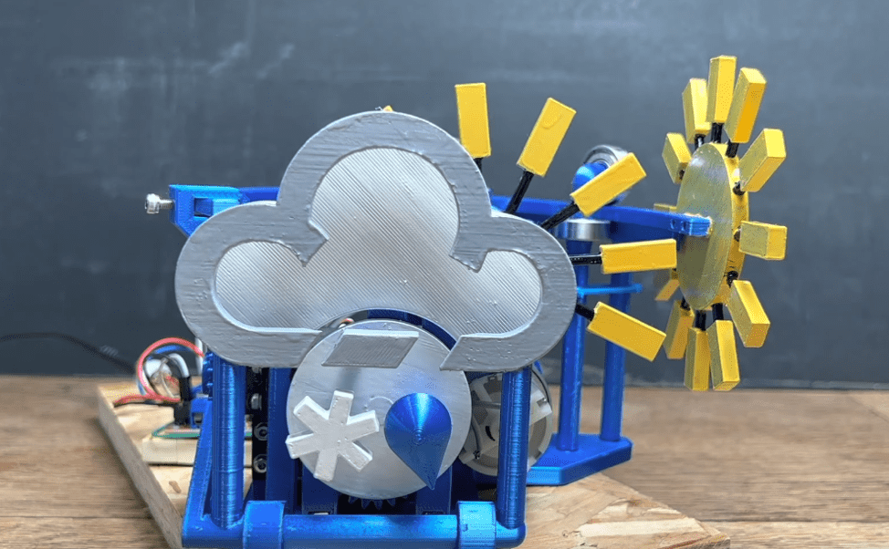
Going outside to see the weather is time consuming and merely looking at a phone gets boring, which is what inspired YouTuber Mikey Makes to build a fun weather-telling device that displays the current conditions in a new format. Owing to his love of the old BBC weather symbols, which were placed on physical stickers rather than a computer screen, Mikey Makes wanted to replicate them and physically swap out various components in a mechanical fashion.
At the very front is a large gray cloud that is permanently fixed in place. If the conditions outside become cloudy, rainy, or snowy, small symbols for each state are rotated underneath the cloud using a stepper motor in conjunction with a DC gear motor. The symbols for partly cloudy and full sun were tougher to integrate since they are either behind the cloud or completely cover it. For partial sun, a series of disks rotate behind the cloud to slowly pull up the rays of sunshine that emanate outwards. Otherwise, full sun causes a large sun symbol to move across the front of the cloud and block it entirely.
Controlling all of these components is a MKR WiFi 1010, which pulls real-time weather data from the openweathermap API. Then depending on the desired movements, it sends signals to an A4988 stepper motor driver or an H-bridge module for the DC motors.
To see more about how this project works and its intricate mechanical design, you can watch Mikey Makes’ demonstration video below!
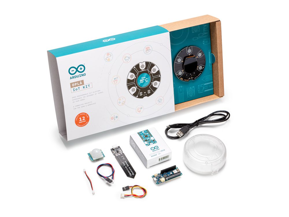
A big part of the Oplà IoT Kit’s value comes from its online content. When you get the kit, one of the first tasks is to visit opla.arduino.cc, where a host of awesome resources are available.
And now it’s expanding on its usefulness by adding four new languages to the content.
Let’s Talk About the Oplà
The Oplà IoT Kit is a very powerful and fully featured learning tool. It’s also got everything an experienced maker needs for a connected project, of course, but if you’re new to Arduino the Oplà is a fantastic introduction.
The kit is supported by its very own website, which offers getting started guides for the bundled MKR IoT Carrier and for Arduino Cloud. The entire kit is all about building IoT projects, so the Cloud is an essential part of that, and it’s important to learn your way around it just as much as the hardware and sensors.
Project guides include a host of great ways to learn about the Oplà IoT Kit, from remote controlled lights to weather stations, security alarms and even a solar system tracker. So it’s easy to see how this online resource ramps up the usability of the kit significantly.
The good news is that it’s now even more useful, thanks to a range of new translations. French, German, Spanish and Italian speaking users can switch the entire Oplà site’s content into their native language. There’s a selector button in the top right corner of the screen that changes all the posts into your preferred language.
We’d love to hear your thoughts on it, especially from makers who speak these newly added languages natively. Anything we can do to improve, just let us know. In the meantime, grab your Oplà IoT Kit and dive into all that delicious multilingual content!
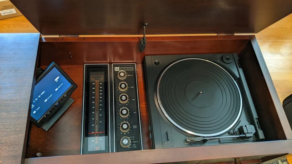
The aphorism that “they don’t build them like they used to” is especially true of the consumer electronics industry. Most manufacturers today design their product to last only a few years — or with outright planned obsolescence. But mid-century stereo consoles were a different story and resembled high-end furniture that would last. Sherman Banks has a Penncrest stereo console from that era, but its electronics were failing. So he used an Arduino to modernize the unit while retaining the vintage appearance.
This particular console had an AM/stereo FM radio receiver and a built-in phonograph turntable. Unfortunately, the aging electronic components were unreliable and lacked good sound quality. The console itself, however, was in fantastic shape. So Banks wanted to keep it looking as original as possible, but with modern electronics and all of the features they offer. He replaced the radio with a Denon DRA-800H stereo receiver that offered inputs for a turntable and SiriusXM receiver, as well as Bluetooth streaming and Ethernet connections. He also replaced the turntable with a new Denon DP-29F.
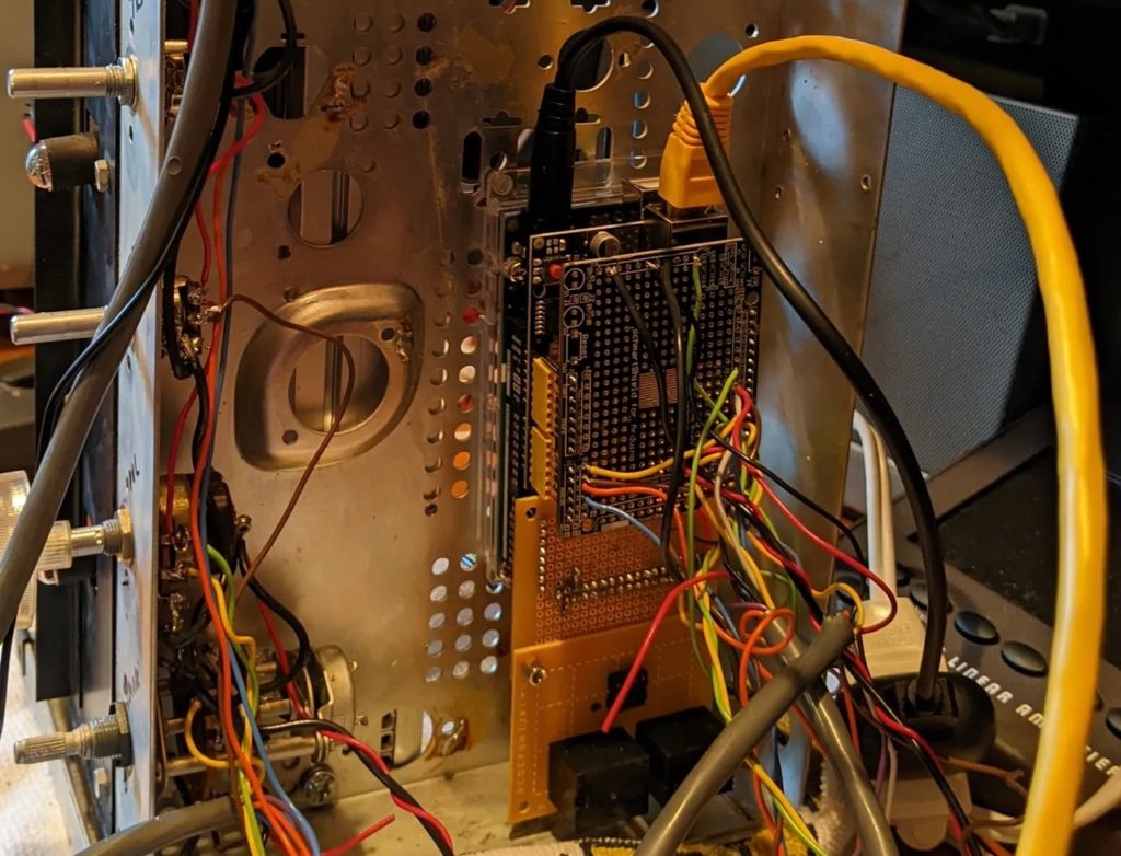
Those would have worked just fine, but he wanted the original controls to work. For that, Banks used an Arduino Mega 2560 board. It reads the inputs from potentiometer knobs for volume, radio tuning, input selection, and so on. It then passes that information over to the stereo receiver through an Ethernet Shield. The stereo accepts network commands to change the radio station, inputs, and other important functions. It also outputs that information, which let Banks set the dial to the appropriate position. The Arduino receives the station number and then uses a stepper motor with a leadscrew and block to move the dial indicator back and forth to the correct position.
Now Banks has a stereo console that looks completely vintage, but which offers all of the modern quality and convenience that he could want.
Displaying the time these days is trivial — you could do it with any Arduino board and a simple four-digit seven-segment display. But as humans, we crave novelty and it isn’t uncommon to see a clock that is more art than a practical timekeeping device. That is true of AKUROBATTO, which is an insane kinetic clock robot that flips itself into position.
AKUROBATTO consists of a skateboard deck-shaped platform and a motorized robot. The robot acts like the hands of an analog clock, with two arms joined by a pivot joint. One can tell the time by judging the relative angular positions of the two arms. That sounds straightforward, but it gets more interesting when you realize that the pivot point between the two arms is not hard-mounted. So to change the angle between the arms, the robot must lock itself into place on the platform and then flip around.
It achieves that movement using two geared stepper motors and two clever servo-driven locking mechanisms. The latter let the robot latch onto the platform in one of two locations. Two Arduino Mini boards control the movement and monitor the angle through an AS5600 rotary encoder sensor. The Arduinos communicate with each other using a pair of nRF24L01 radio transceivers.
But the mechanical design is what truly sets AKUROBATTO apart. Its structure is 3D-printed, but it utilizes an ingenious system of locking rings and GT2 timing belts to transfer torque for movement. It is difficult to even comprehend without seeing the movement for yourself, which is exactly as kinetic art should be.
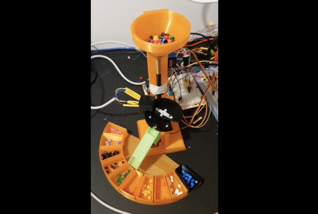
If you want to measure the blueness of an object, you can shine a pure blue light at it and then measure the reflected light intensity with a photodiode. Do the same for red and green light, and you can get an RGB color value. Conversely, you can shine a white light at an object and use three photodiodes with the appropriate color filters to calculate your RGB levels. This sorter, built by Redditor Dumjim, relies on these principles to organize large quantities of beads.
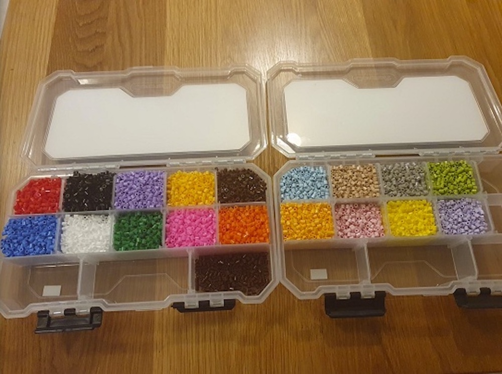
This machine sorts the kinds of beads used for beadwork crafting. Those may come in individual containers, but they soon end up mixed up. But now, Dumjim can quickly and easily sort those beads by color. It utilizes a 3D-printed frame and mechanisms, which Dumjim designed in Autodesk Inventor CAD software.
The brain of the machine is an Arduino Uno, which inspects each bead using a color sensor that operates with white light with filtered photodiodes. A unique servo-driven mechanism feeds beads from a hopper down to the sensor. Based on the color values, it uses a second servo-driven mechanism to drop the beads down a chute and into separate containers. These same principles would work for sorting uniform objects of any kind by color, but it is especially suited to the tiny beads that frustrate crafters.
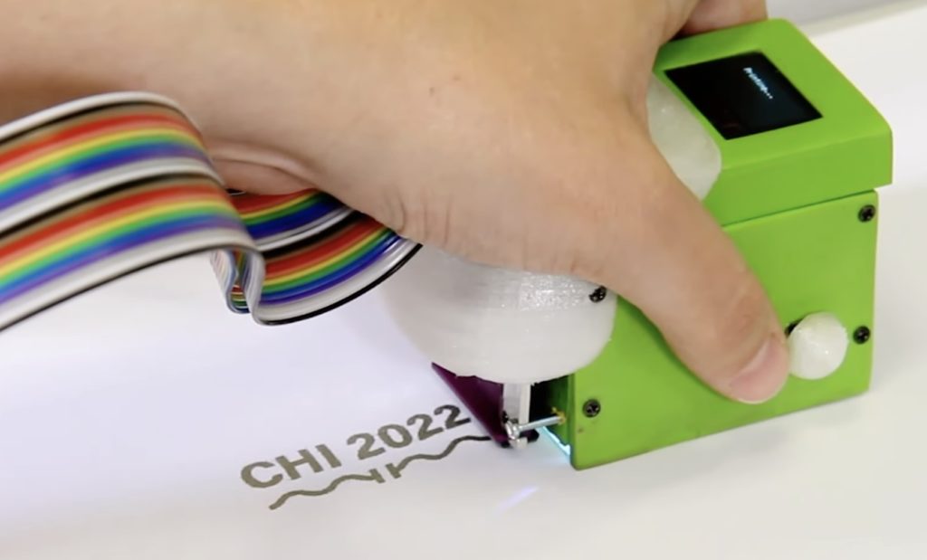
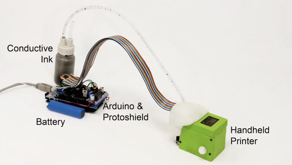
The creation of conductive ink has enabled anyone with a brush to sit down and sketch out an entire circuit on a wide variety of surfaces, although this process comes with a few large drawbacks. Compared to digital fabrication techniques, such as designing and manufacturing PCBs, the drawn traces are often inconsistent and messy, leading to unsightly and unreliable circuits. To fix this problem, a team from Saarland University in Saarbrücken, Germany came up with an intelligent handheld printer called Print-A-Sketch that can automatically correct user errors while also providing a wide range of tools for drawing incredible designs on anything.
The unit is based around an Arduino Mega 2560, which collects movement data from an optical motion sensor and uses it to make small adjustments. From there, the piezoelectric printhead utilizes changes in current to control a matrix of ink-laying dots that can deposit ink at a steady pace depending on how fast the user is moving the device. Finally, a wide-angle RGB camera module, OLED screen, and joystick allow for a user to interact with the printer.
Apart from merely drawing straight lines on a page, the printer can also deposit custom shapes, continue printing a line that had been drawn previously, and even scan components on-the-fly to print their footprints. All of these capabilities can be combined to create devices such as smart yoga mats, capacitive controls, and even flexible sensors across a wide range of surfaces.
For more details on the Print-A-Sketch, you can read the team’s paper here and watch its demo video below!
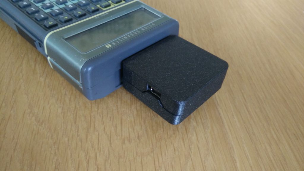
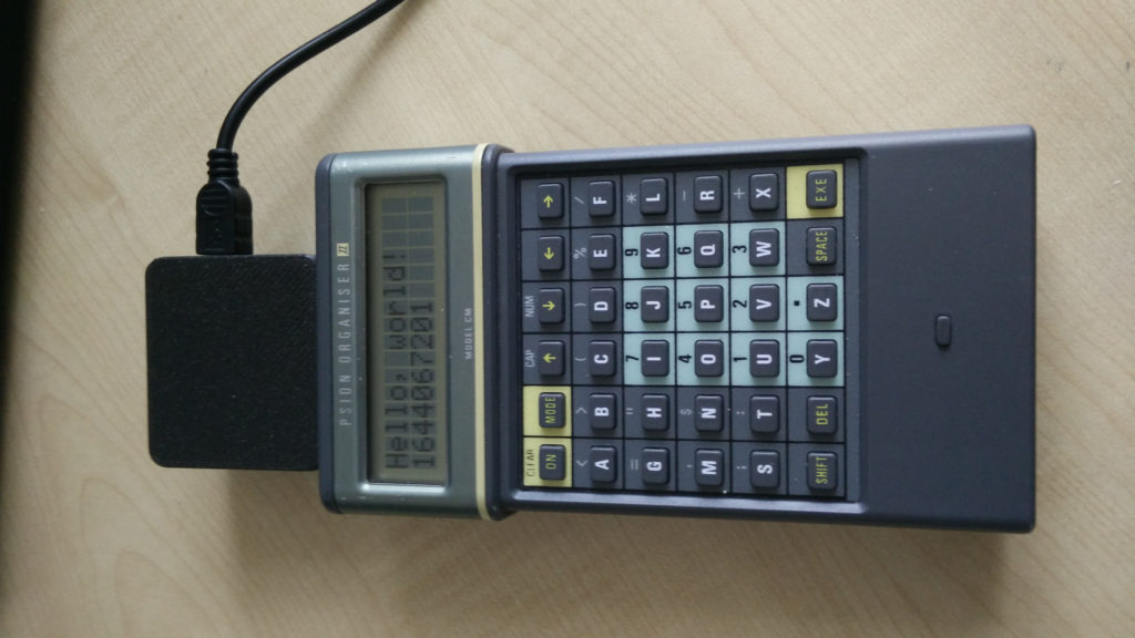
The Psion Organiser I, released in 1984, was a pocket computer — the kind of device that would soon fit the description of a PDA (personal digital assistant). Its successor, the Psion Organiser II, was similar and included a tactile keyboard, a small LCD screen, a processor, and memory, so users could write and run programs. James Stanley created an Arduino-based adapter for the Psion Organiser II that turns it into a USB display.
The Psion Oganiser II had three peripheral ports. Two were for “datapaks,” which were expansion modules (including UV-erasable EPROM). The third is for a communications cable. Unfortunately, it is hard to find a CommsLink cable today. So Stanley created his own adapter. But this came with a challenge: two-way serial communication with the Psion Organiser II’s CPU requires precise timing. Without dedicated hardware built for this serial protocol, communication is difficult for even modern microcontrollers to handle in software. And one-way communication can interfere with the datapaks and cause issues.
Stanley’s solution was very clever. He connected an Arduino Nano board’s digital IO pins to the CPU’s “port 2” data bus through 510 ohm resistors. Those resistors fit into a goldilocks where the Arduino can pull the data lines high or low, but only if that doesn’t contradict communication between the datapaks and the CPU. So datapak communication will take priority. If no communication is occurring between the datapaks and CPU, the Arduino can send data directly to the CPU. In practice, as machine code sent through the Arduino’s serial port that will display a desired text string on the Psion Organiser II’s LCD screen.
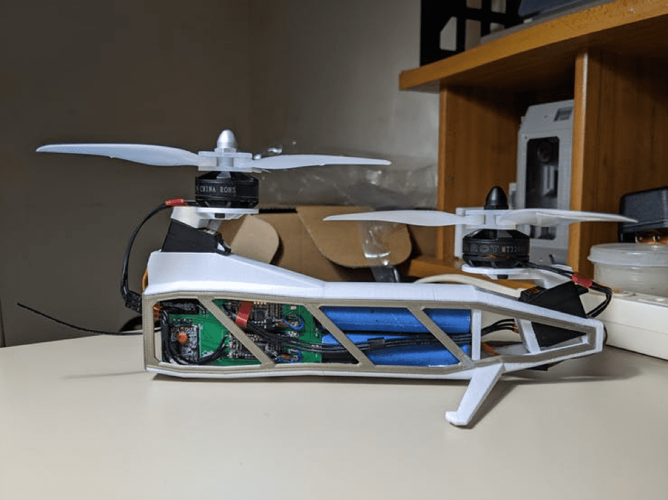
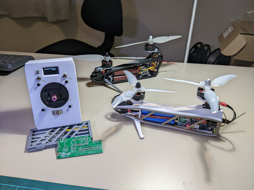
The classic helicopter design that everyone is familiar with features a large central rotor that produces lift and a much smaller one towards the back, which prevents the helicopter from spiraling out of control. However, Redditor CCCanyon decided to take inspiration from Boeing’s CH-47 Chinook that leverages a pair of equally sized and offset rotors that work together to both move the helicopter while remaining steady.
The most apparent feature of the project is the unique 3D-printed frame that houses the electronics, batteries, and motors required for flight. The controller is a single Arduino Nano 33 IoT, which constantly takes measurements from its onboard LSM6DS3 six-axis IMU and sends that data through a PID algorithm to create small adjustments. The pilot is able to control the aircraft by manipulating a single-stick controller that sends commands from its LoRa SX1276 transceiver to the bicopter’s. Finally, the two rotors are spun by brushless DC motors that were set atop servo motors, which tilt them in order to modify the heading.
This project, along with the from-scratch code required to make it work, is very impressive, as can be seen in the demo video below. CCCanyon is also currently working on a second version of the bicopter, and it will be exciting to see which improvements have been made.
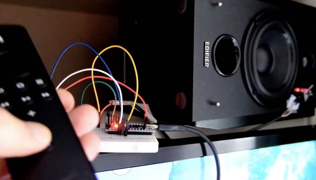
All too often, people run into the issue of having many remotely controlled devices scattered around their house, with each requiring its own unique controller. The idea behind how they operate is simple: a single action corresponds to a number and pressing a button on the controller causes that number, along with some extra data, to be modulated via an infrared LED which reaches the device’s receiver. Finally, this value is decoded and the action is executed.
In order to combine all of these differing code patterns into a single place, YouTuber Endpoint101 decided to use an Arduino Nano plus an infrared receiver and separate emitter to act as a translator for an Amazon Fire TV remote, creating a truly universal remote control. Whenever a new device is being added, he must first press the button on the target device’s controller, which can be anything from a direction, media playback, or a volume adjustment, where it’s then read by the Nano and stored. The last step is essentially creating a map between the already known codes from the Fire TV remote and setting them equal to the desired code.
With this system, Endpoint101 can now activate any device he wants with just a single remote controller rather than having to search endlessly for the right one. To see more about this project, watch the video below!
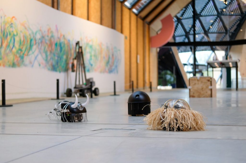
If you’re like most people, you click “accept all” whenever a website asks you to allow cookies. That button is big and enticing, begging you to click so you can get to your content without thinking about the purpose of the cookies. That purpose is usually to serve you personalized ads, but you let the website track you because it asked you in a nice way. To replicate that effect in a tangible way, Guillaume Slizewicz built these Arduino-controlled robots.
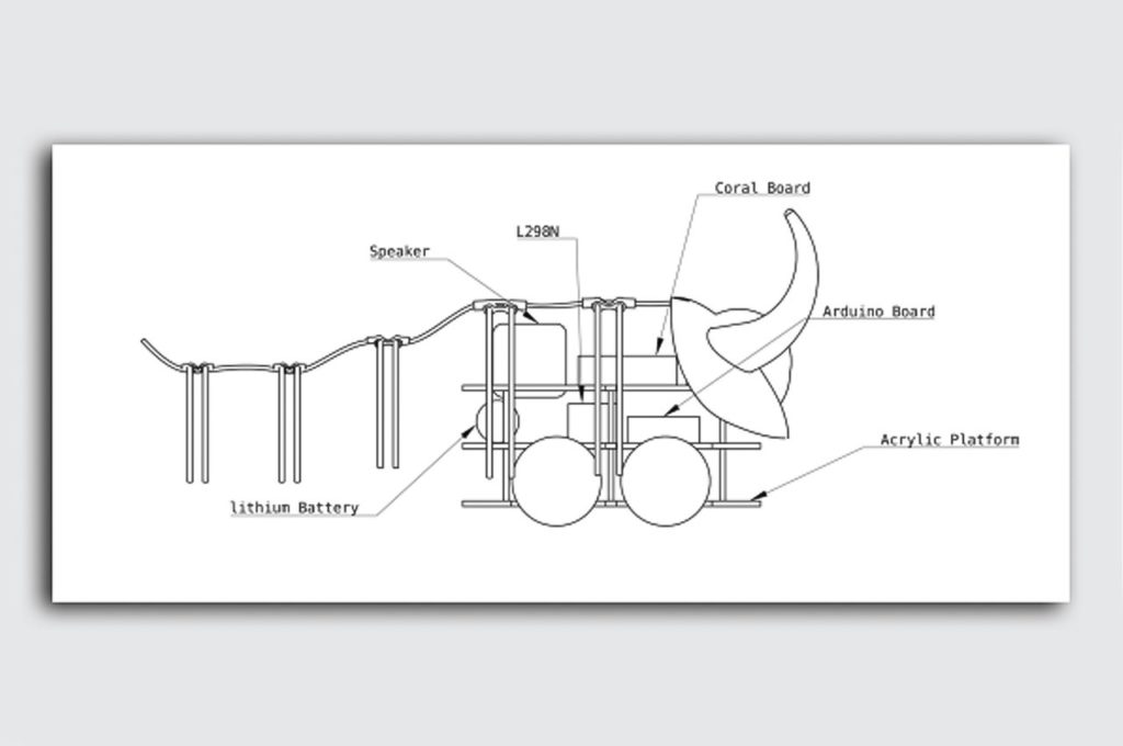
“Accept All” is an art installation Nemur, Belgium’s Le Pavillon. It consists of a few small wheeled robots that drive around the room. When they see a person, they scurry over to bump into that person’s shins. And people are happy to let them, because the robots are very cute. One has silly little horns. Another wears a grass hula skirt. Another looks like a jelly fish going through a goth phase. As with Internet cookies, people comply with the robots’ minor annoyance because they are pleasant.
But, like cookies, these robots are tracking people. A Google Coral AI board peers at the world through a small camera and detects people by using an OpenCV script. When a robot sees someone, its Coral board sends a command to an Arduino via serial. The Arduino then controls drive motors that push the robot into the person’s legs. Slizewicz doesn’t actually collect data on the people his robots encounter. But the point is that he could and nobody would mind, since the robots are endearing.
Wevolver’s previous article about the Arduino Pro ecosystem outlined how embedded sensors play a key role in transforming machines and automation devices to Cyber Physical Production Systems (CPPS). Using CPPS systems, manufacturers and automation solution providers capture data from the shop floor and use it for optimizations in areas like production schedules, process control, and quality management. These optimizations leverage advanced data Internet of Things (IoT) analytics over manufacturing datasets, which is the reason why data are the new oil.
Deployment Options for IoT Analytics: From Cloud Analytics to TinyML
IoT analytics entail statistical data processing and employ Machine Learning (ML) functions, including Deep Learning (DL) techniques i.e., ML based on deep neural networks. Many manufacturing enterprises deploy IoT analytics in the cloud. Cloud IoT analytics use the vast amounts of cloud data to train accurate DL models. Accuracy is important for many industrial use cases like Remaining Useful Life calculation in predictive maintenance. Nevertheless, it is also possible to execute analytics at the edge of the network. Edge analytics are deployed within embedded devices or edge computing clusters at the factory’s Local Area Network (LAN). They are appropriate for real-time use cases that demand low latency such as real-time detection of defects. Edge analytics are more power-efficient than cloud analytics. Moreover, they offer increased data protection as data stays within the LAN.
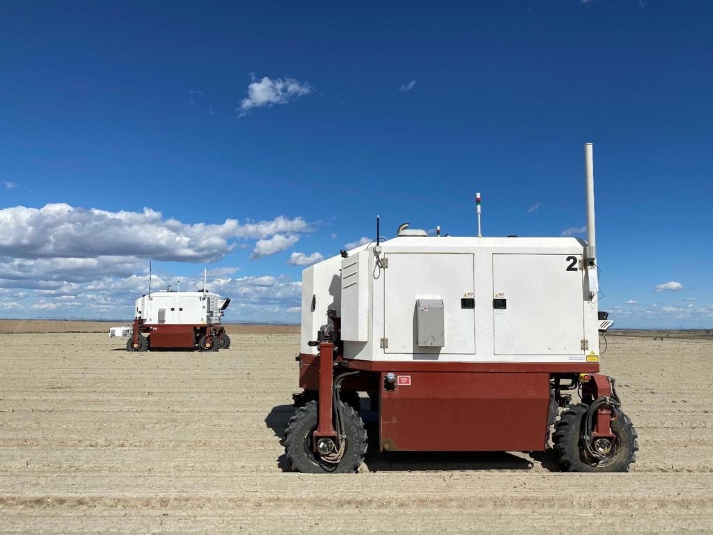
During the last couple of years, industrial organizations use TinyML to execute ML models within CPU and memory-constrained devices. TinyML is faster, real-time, more power-efficient, and more privacy-friendly than any other form of edge analytics. Therefore, it provides benefits for many Industry 4.0 use cases.
TinyML is the faster, real-time, most power-efficient, and most privacy friendly form of edge analytics. Image credit: Carbon Robotics.
Building TinyML Applications
The process of developing and deploying TinyML applications entails:
Getting or Producing a Dataset, which is used for training the TinyML model. In this direction, data from sensors or production logs can be used.
Train an ML or DL Model, using standard tools and libraries like Jupyter Notebooks and Python packages like TensorFlow and NumPy. The work entails Exploratory Data Analysis steps towards understanding the data, identifying proper ML models, and preparing the data for training them.
Evaluate the Model’s Performance, using the trained model predictions and calculating various error metrics Depending on the achieved performance, the TinyML engineer may have to improve the model and avoid overfitting on the data. Different models must be tested to find the best one.
Make the Model Appropriate to Run on an Embedded Device, using tools like TensorFlow Lite which provides a “converter” library that turns a model into a space-efficient format. TensorFlow Lite provides also an “interpreter” library that runs the converted model using the most efficient operations for a given device. In this step, a C/C++ sketch is produced to enable on device deployment.
On-device Inference and Binary Development, which involves the C/C++ and embedded systems development part and produces a binary application for on-device inference.
Deploying the Binary to a Microcontroller, which makes the microcontroller able to analyse data and derive real-time insights.
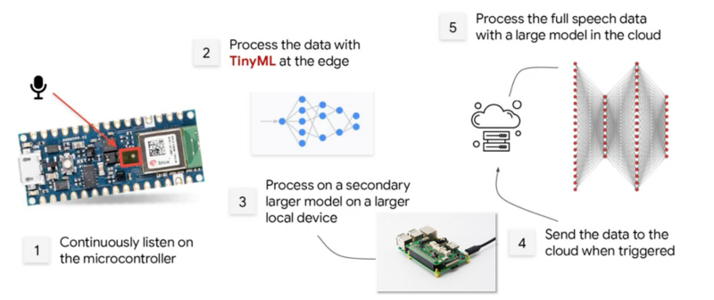
Building a Google Assistant using tinyML. Image credit: Arduino.
Leveraging AutoML for Faster Development with Arduino Pro
Nowadays, Automatic Machine Learning (AutoML) tools are used to develop TinyML on various boards, including Arduino boards. Emerging platforms such as Edge Impulse, Qeexo and SensiML, among others, provide AutoML tools and developers’ resources for embedded ML development. Arduino is collaborating with such platforms as part of their strategy to make complex technologies open and simple to use by anyone.
Within these platforms, users collect real-world sensor data, train ML models on the cloud, and ultimately deploy the model back to an Arduino device. It is also possible to integrate ML models with Arduino sketches based on simple function calls. AutoML pipelines ease the tasks of (re)developing and (re)deploying models to meet complex requirements.
The collaboration between Arduino and ML platforms enables thousands of developers to build applications that embed intelligence in smart devices such as applications that recognize spoken keywords, gestures, and animals. Implementing applications that control IoT devices via natural language or gestures is relatively straightforward for developers who are familiar with Arduino boards.
Arduino has recently introduced its new Arduino Pro ecosystem of industrial-grade products and services, which support the full development, production and operation lifecycle from Hardware and Firmware to Low Code, Clouds, and Mobile Apps. The Pro ecosystem empowers thousands of developers to jump into Industry 4.0 development and to employ advanced edge analytics.
Big opportunity at every scale
The Arduino ecosystem provides excellent support for TinyML, including boards that ease TinyML development, as well as relevant tools and documentation. For instance, the Arduino Nano 33 BLE Sense board is one of the most popular boards for TinyML. It comes with a well-known form factor and various embedded sensors. The latter include a 9-axis inertial sensor that makes the board ideal for wearable devices, as well as for humidity and temperature sensors. As another example, Arduino’s Portenta H7 board includes two asymmetric cores, which enables simultaneously runs of high level code such as protocol stacks, machine learning or even interpreted languages (e.g., MicroPython or JavaScript). Furthermore, the Arduino IDE (Integrated Development Environment) provides the means for customizing embedded ML pipelines and deploying them in Arduino boards.
In a Nutshell
ML and AI models need not always to run over powerful clouds and related High Performance Computing services. It is also possible to execute neural networks over tiny memory-limited devices like microcontrollers, which opens unprecedented opportunities for pervasive intelligence. The Arduino ecosystem offers developers the resources they need to ride the wave of Industry 4.0 and TinyML. Arduino boards and the IDE lower the barriers for thousands of developers to engage with IoT analytics for industrial intelligence.
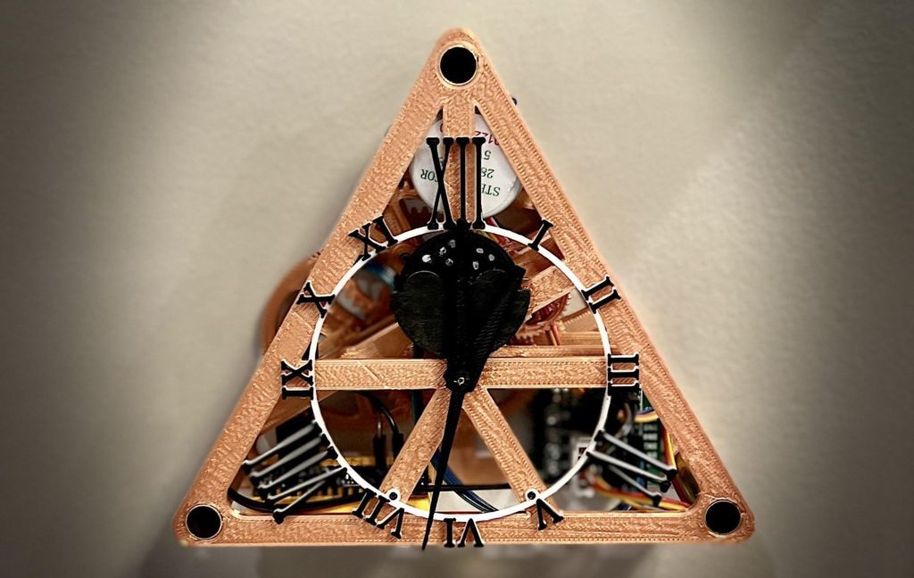
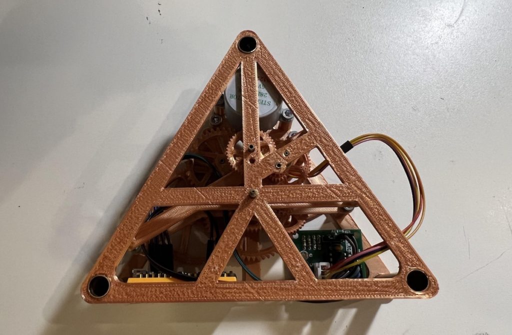
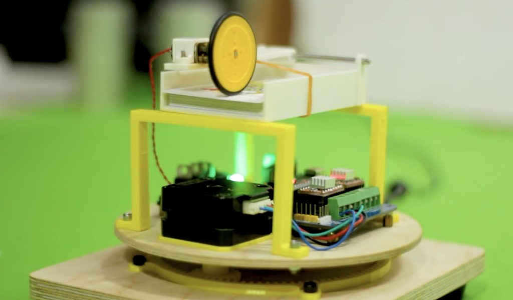
Back in April 2021, Instructables user saulemmetquinn had the idea to build a fully 3D-printed clock that was based on the Triangulum constellation, which as the name implies, is a triangle. But it wouldn’t only tell the time using the typical set of hands and numbers, but also the current phase of the moon to stick with the astronomical theme.
To begin, Saul made a detailed mechanical model in CAD, complete with every facet and gear necessary for it to run. In short, the clock contains a spinning stepper motor that completes one rotation every 15 seconds (a ratio of 1:15). When combined with a series of reduction gears, this rate slows all the way down to 1:43200 for a single hour. In addition to the second, minute, and hour hands, an extra set of gears were added with a collective ratio of 99:2924 that keep track of the current moon phase.
After carefully assembling the clock by hand after printing each part, the ubiquitous ULN2003 stepper motor driver and 5V 28BYJ-48 were added to an inner panel along with an Arduino Nano Every. This board was selected due to its small size and larger memory footprint, which made running the Holo Clock firmware simple.
To read more about this project, you can visit Saul’s write-up here on Instructables.
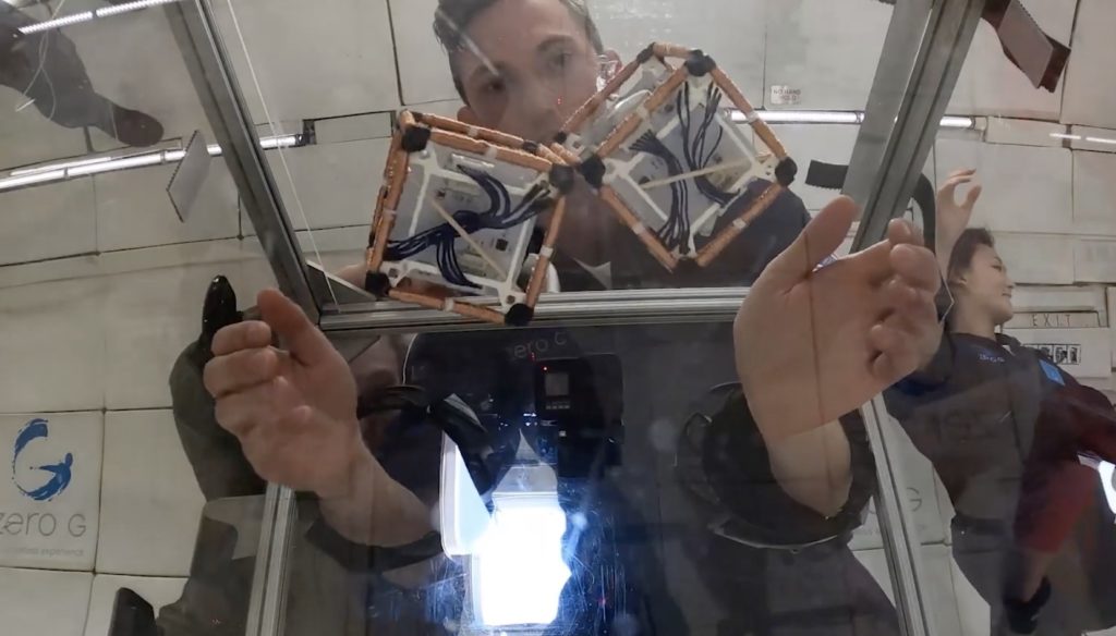
The ability to control magnetism is very powerful and acts as the basis for huge swaths of modern technology. Without electromagnetism, we likely would never have progressed into the digital age — we wouldn’t even have electric motors. Now engineers from MIT CSAIL are using electromagnetism for something new: reconfigurable robots.
ElectroVoxel robots are cube-shaped modules that can self-assemble into more complex shapes. Each robot has electromagnet coils lining its edges. An Arduino Nano with a wireless transceiver drives those electromagnets, allowing for untethered operation. Power comes from LiPo batteries and the frames are 3D-printed. By controlling the current and polarity of each electromagnet, the robots can cling to each other. They can also move by using an attractive edge connection for a pivot point and repulsion for actuation. They can use that movement for basic locomotion or to reconfigure into new shapes.
Unfortunately, ElectroVoxel robots only work in microgravity. Earth’s gravity is too strong for their electromagnetic repulsion to overcome for a pivot motion. For that reason, the engineers were forced to test the ElectroVoxel robots in “vomit comet” parabolic plane flight, which creates a microgravity effect. In that environment, the robots successfully reconfigured themselves into a variety of shapes without any external manipulation.
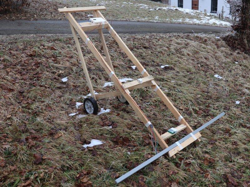
Magnetometers are devices that use various techniques to measure certain aspects of magnetism, including direction, strength, or relative changes. By combining these and applying some math, underground and other hidden structures can be discovered without the risk of damaging anything sitting below the sensor. This is why Markus Opitz decided to build a large-scale magnetometer using simple components in order to map things around his property.
The basic structure of the device consists of a basic frame made from several wooden planks with a pair of wheels at its base and a wide piece of aluminum tubing to hold the sensor array. To gather raw data, Opitz started by integrating seven Hall effect sensors with a digital compass and an Arduino Mega.
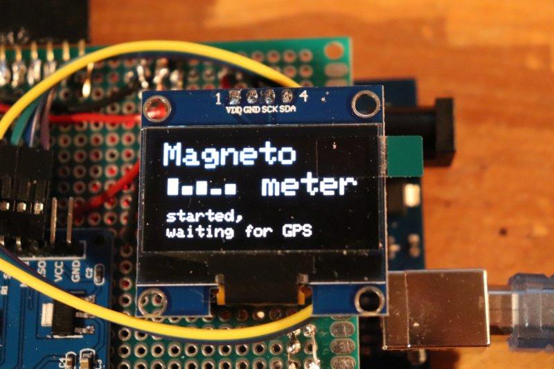
Coordinates are determined by the onboard GPS module and logged to an SD card along with the readings from the attached sensors. Finally, the current heading is defined via a digital compass and displayed in addition to other data on a 128x64px OLED screen.
After wheeling the unit around an outdoor area for a while and gathering ample amounts of data, Opitz loaded the logs into qGIS that combines headings, magnetic values, and coordinates along with a satellite map into a single image.
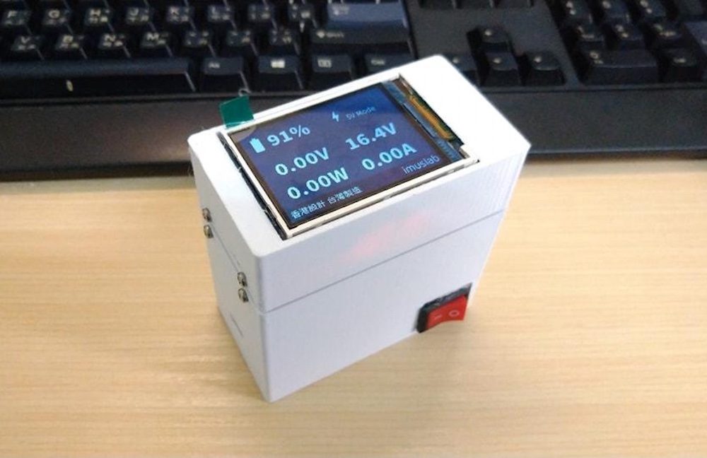
The advent of USB-C and the power delivery (PD) standard have allowed for a single cable to carry both large amounts of data and power for a wide range of devices. So, while looking for a PD-capable power bank for his laptop but only coming across expensive units, Instructables user Toby Chui decided to make his own — with additional improvements, of course.
The design for this custom power bank started with a basic schematic consisting of the LiPo battery, a 60W PD module for handling the negotiations between the board and whatever device might be on the other end, and a display unit for showing current battery information. After soldering together a small piece of perfboard containing a buck converter, voltage divider for voltage measurements, and an ACS712 current sensor, Chui glued the entire assembly onto the back of a UART HMI display. The last component was an Arduino Nano that takes in voltage/current readings and sends them to the display, along with the current voltage being delivered over the USB-C cable and the total power consumption.
With the electronics finished, Chui modeled and 3D-printed a small case that holds the battery and switch at the base while the screen at the top displays the information. You can read more about this project here on Instructables.
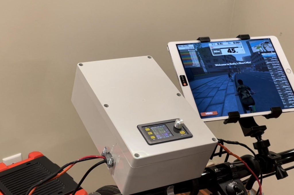
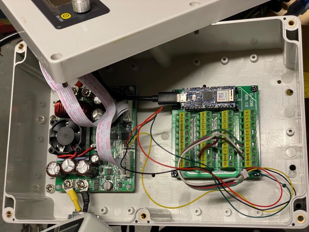
Zwift is a neat cycling simulator app that lets you experience a variety of bicycle adventures from the comfort of your living room. You can participate in bike races, cruise your favorite trails, or go on a leisurely ride through the country. Zwift’s key feature is that it reacts to your pedaling and vice-versa. So an uphill section increases the pedaling difficulty and your in-game speed correlates to your pedaling speed. Gene’s Green Machine found a way to integrate an existing bike with Zwift using Arduino.
In order for this to work, you will need an indoor bike setup with a pedal generator. The generator creates resistance and its voltage output is proportional to the gear ratio and pedaling speed. By monitoring the voltage, you can tell Zwift how fast your virtual bike should move. Conversely, Zwift can adjust the real world pedaling resistance based on the virtual conditions. Steering isn’t a factor here, but that isn’t a major part of cycling at speed anyway. You also don’t get to experience the virtual weather elements, but that is a good thing as far as most people are concerned.
The primary component for this project is an Arduino Nano 33 IoT board, but you can also use a Nano 33 BLE, Uno WiFi Rev2, or MKR WiFi 1010. The Arduino will monitor the voltage coming from the pedal generator through a DPS5020 charge controller, which also charges up batteries — no sense in wasting all of that sweat you’re putting into pumping the pedals. The Arduino connects to Zwift over Bluetooth by utilizing the Bluetooth Low Energy Fitness Machine Service that exists specifically for this purpose.
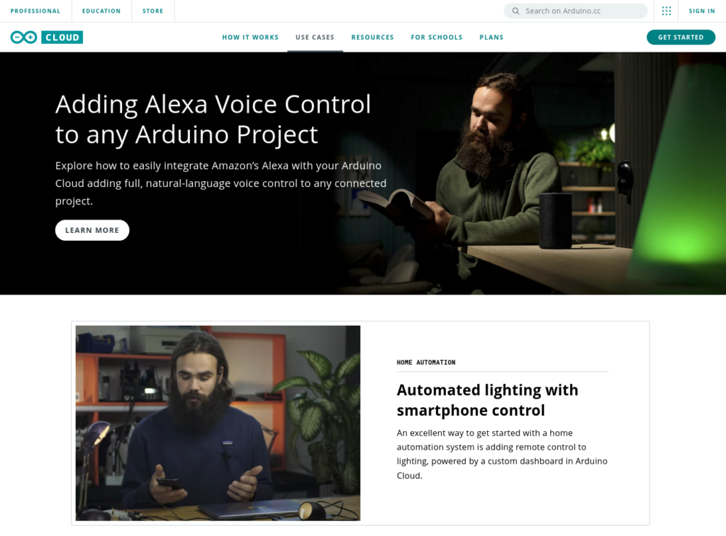
As Arduino Cloud continues to evolve and we see more and more people adopting the platform, we wanted to make sure there was a strong focal point for newcomers to find out what it’s all about. Which is why we just released cloud.arduino.cc, to give you a one-stop shop for learning everything about Arduino Cloud.
cloud.arduino.cc
There’s a lot rapid development around Arduino Cloud since the webpage was first launched. Excitement both inside and outside Arduino for delivering new Cloud features and improvements has, admittedly, overtaken our efforts to keep the webpage spick and span. The cobbler’s shoes always has holes in them, as the saying goes!
But no longer. Our web team has been working hard since well before Christmas to give Arduino Cloud the webpage it deserves. It’s a place where newcomers can easily learn what it’s all about and what it offers, and it’s somewhere that experienced Cloud users can stay up to date.
Everything About Arduino Cloud
The new page is broken down into a variety of different sections, intended to make it as easy as possible to learn when you want, and find what you need.
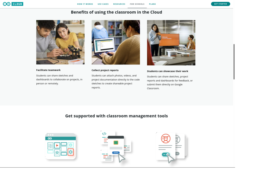
Whether it’s info about features, the different plans, getting started or news about new developments, it’s all found a home at cloud.arduino.cc. All the resources you need are gathered together there, including learning how you can use Arduino Cloud in the classroom.
There’s also a whole section dedicated to use cases, which we’re particularly excited about. Use cases are an excellent place to learn what you can do with the Cloud, and to get inspiration. But they’re also an excellent showcase of what people in the Arduino Community have achieved.
So to that end, we’re always keen to hear from anyone out there who has a working example of an Arduino Cloud project, and wants to show it off. Get in touch if you think your project might be suitable for an official Arduino Cloud use case.
In the meantime, please take a look at the brand new home for Arduino Cloud, and share it far and wide with the rest of the community.
If you’ve ever dealt cards the “wrong way” among serious poker players, then you know that some people do not take the dealing process lightly. You must deal cards in the proper order, one to each player before starting back at the first, without ever showing a card. If that sounds like a hassle to you, you can build this card-dealing robot designed by Mr Innovative.
This simple robot accepts a standard deck of playing cards and deals a preset number of cards to a preset number of players. We would like to see it have some sort of interface to select the number of players and how many cards they receive, but that would be easy to add to the design. It is small enough to fit on any card table and can deal at a fast pace without flinging cards too far.
An Arduino Nano board controls the robot. Mr Innovative used that with a custom multipurpose PCB that he designed for his many projects. In this case, it lets the Arduino drive both a stepper motor and a DC motor. The stepper motor rotates the entire upper assembly on a Lazy Susan-like turntable to point at each player position. The DC motor spins a gripper wheel that flings the top card of the deck. The stepper motor gears and the deck hopper are 3D-printed. A rubber band provides tension to keep the gripper wheel against the cards.
Sadly for those of us lacking in card handling skills, this robot cannot shuffle the cards before dealing.
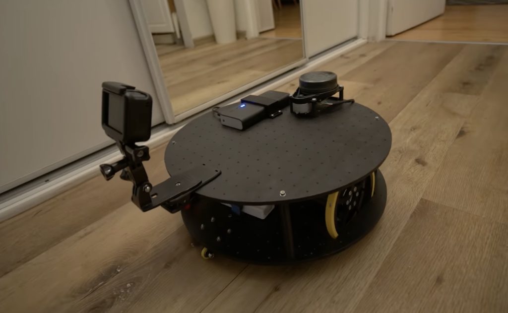
As part of his ongoing autonomous robot project, YouTuber Nikodem Bartnik wanted to add LIDAR mapping/navigation functionality so that his device could see the world in much greater resolution and actively avoid obstacles. In short, LIDAR works by sending out short pulses of invisible light and measuring how much time it takes for the beam to reflect off an object and return to its detector. By combining this distance value with the angle of the sensor at the moment of measurement, a virtual cloud of points can be built and used to represent the entire space around the robot.
The LIDAR module Bartnik opted to use was fairly simple, as it sent measurements in frames over UART that encoded everything including the sensor’s angle, the distance, and the speed of the device. He then created a simple sketch for the MKR WiFi 1010 that takes advantage of the increased power and connectivity to read values and send them to a host machine for further processing and visualization.
The resulting Python script opens a websocket, which receives the aforementioned data, does some basic filtering, and then displays it within a point-cloud. It also determines the direction in which the robot should move and sends that command back to the MKR board so it can tell the attached Arduino Uno how to move the motors.
Portenta Cat. M1/NB IoT GNSS Shield: Connectivity and positioning for your boards
Arduino Team — January 31st, 2022
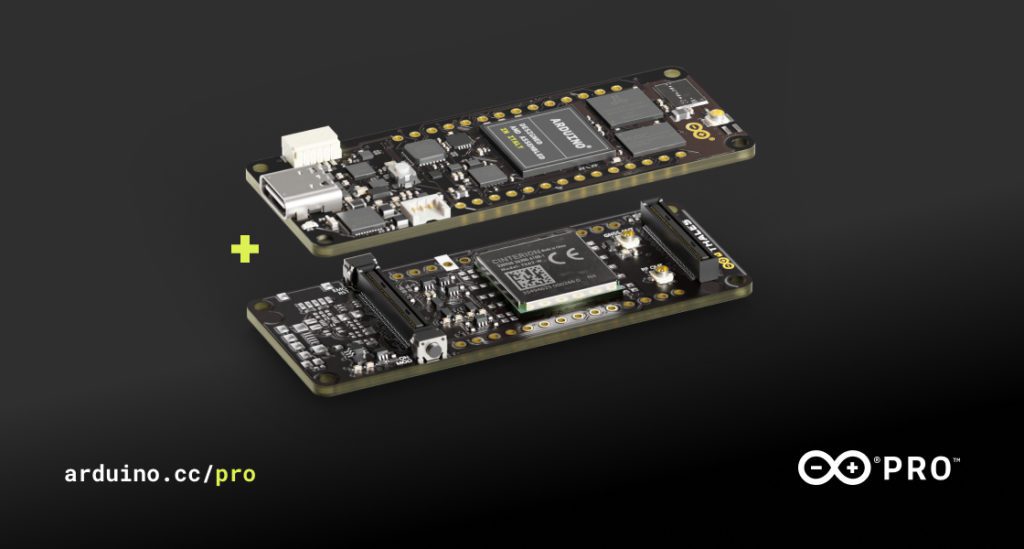
Despite how powerful and high-performance we make our boards, we know some of you always want more – especially in the fast-evolving Industry 4.0! Enter the Portenta Cat. M1/NB IoT GNSS Shield, a new product we developed in partnership with aerospace, defense, transportation and security multinational Thales.
It’s what you need to unleash a world of new opportunities for edge computing. By leveraging a Cinterion TX62 wireless module built for highly efficient, low-power IoT applications, the Portenta Cat. M1/NB IoT GNSS Shield delivers optimized bandwidth and performance, while adding global connectivity and positioning capabilities to Portenta and MKR boards.
It is the ideal solution for the development of positioning, tracking and remote monitoring applications in industrial settings, including agriculture, public utilities and smart cities.
With the new Portenta Cat. M1/NB IoT GNSS Shield, you can:
Easily track assets – across the city or worldwide – from personal valuables to entire fleets of vehicles, thanks to the GNSS feature and a choice between GPS, GLONASS, Galileo or BeiDou positioning.
Add cellular capabilities to any Portenta boards connected to local sensors, leveraging the Cat.M1/NB IoT GNSS Shield’s connectivity features.
Get real-time insight from sensors located worldwide relaying geotagged data.
Much more. We’re excited to discover what the Arduino community, clients and partners will be able to do with the extended features and top performance provided by this shield.
Key benefits
Change connectivity capabilities without changing the board
Add NB-IoT, CAT.M1 and positioning to any Portenta or MKR board
Possibility to create a small multiprotocol router (WiFi – BT + NB-IoT/CAT.M1)
Low-power module
What can the Portenta Cat. M1/NB IoT GNSS Shield do for you?
Here are just a few examples:
If you work in agriculture, you can create your own solution for gas detection, optical sensing, machinery alarm systems and even biological bug traps.
If you develop smart city solutions, you could use the Portenta Cat. M1/NB IoT GNSS Shield for a new, intelligent parking system or street lighting, connecting data and automated actions for a truly optimized use of resources and enhanced user experience.
The computational power of the Portenta H7 combined with the Portenta Cat. M1/NB IoT GNSS Shield greatly reduces the communication bandwidth requirements in IoT applications. The Portenta Cat. M1/NB IoT GNSS Shield is specifically designed for edge ML applications, enabling low-power, long-distance communications over NBIoT and CAT.M1 networks.
So, are you ready to take your projects to the next level? Add a Portenta Cat. M1/NB IoT GNSS Shield to your Portenta H7 or MKR board.
The Portenta Cat. M1/NB IoT GNSS Shield is available for €73/$87.60 USD.For more information and full tech specs, please visit the Arduino Pro website.
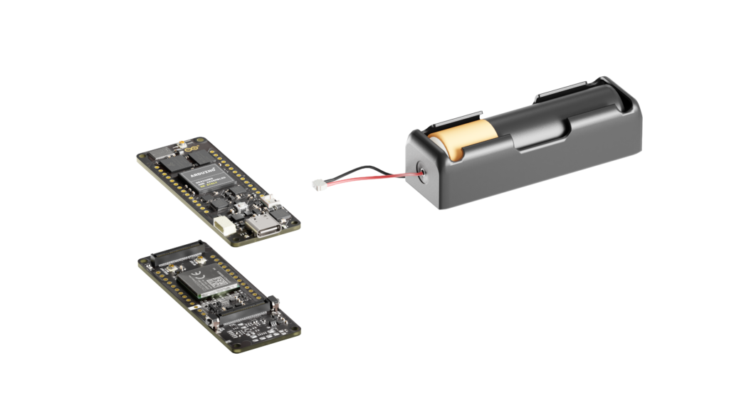
As an entry into the 5th IEEE National Level Project Competition, Anway Pimpalkar and his team wanted to design a system that could help improve safety and usability within elevators by detecting if a human is present, the floor they wish to travel towards, and automatically go to the ground floor in the event of a fire.
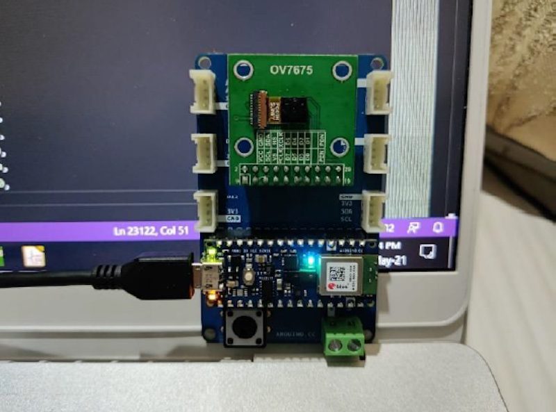
For determining when a person is standing within the elevator’s cabin, Pimpalkar used a Nano 33 BLE Sense and an OV7675 camera module that take advantage of embedded machine learning for facial detection. From there, the Nano will notify the user via a blinking LED that it is ready to accept a verbal command for the floor number and will transport the user when processed. Perhaps most importantly, an MQ-2 smoke sensor and LM-35 temperature sensor were added to the custom PCB. These two pieces of hardware are responsible for sensing if there is a fire nearby and subsequently activating an alarm and then moving the cabin to the ground floor if needed.
Altogether, this project is a great showcase of how powerful tinyML can be when it comes to both safety and accessibility. To read more about the system, you can check out Pimpalkar’s GitHub repository here.
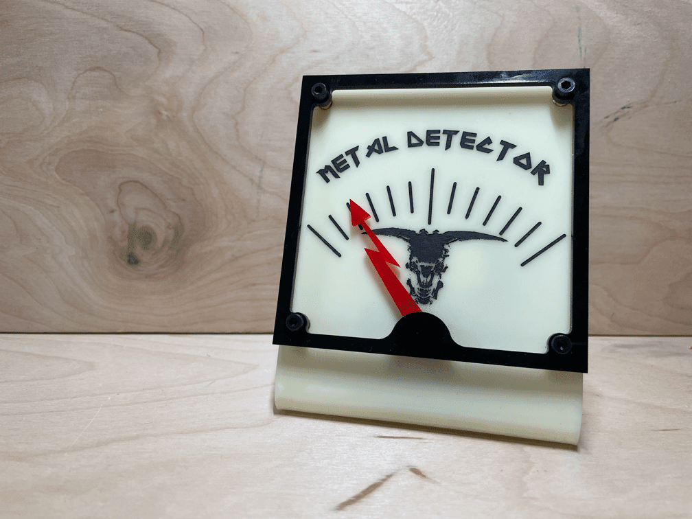
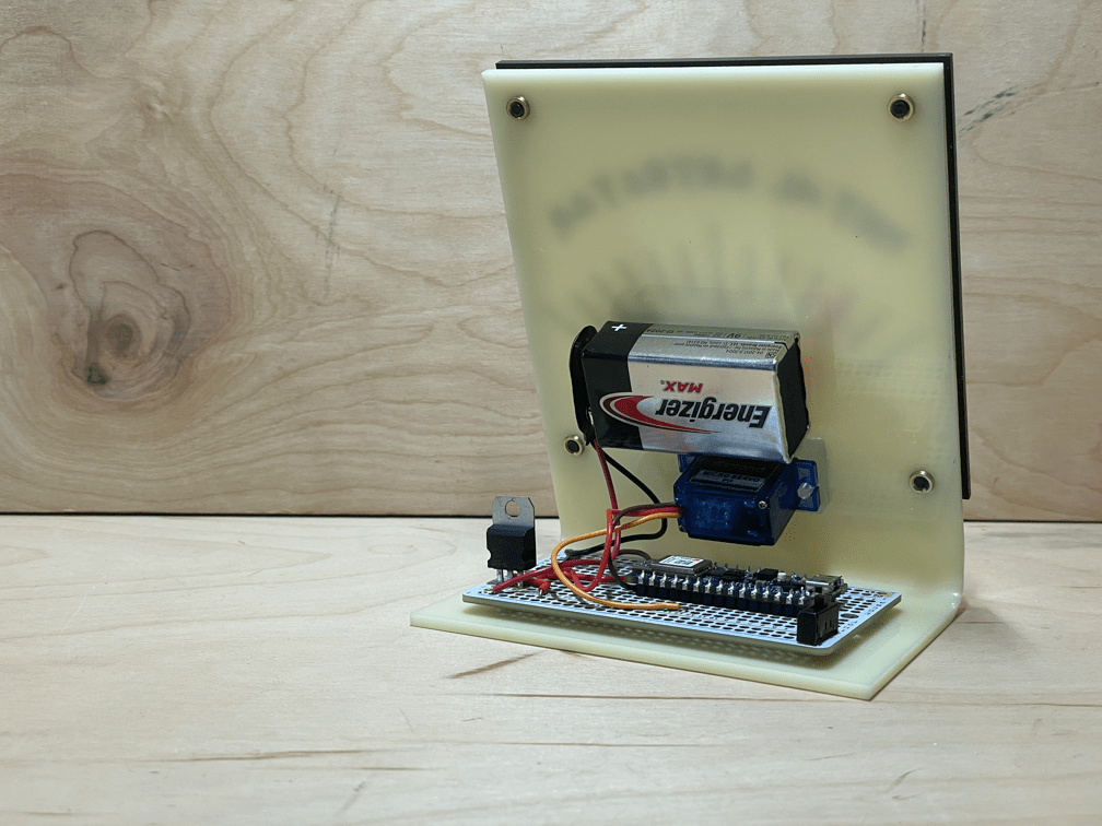
After learning about the basics of embedded ML, industrial designer and educator Phil Caridi had the idea to build a metal detector, but rather than using a coil of wire to sense eddy currents, his device would use a microphone to determine if metal music is playing nearby.
Caridi started out by collecting around two hours of music and then dividing the samples into two labels: “metal” and “non_metal” using Edge Impulse. After that, he began the process of training a neural network after passing each sample through an MFE filter. The end result was a model capable of detecting if a given piece of music is either metal or non-metal with around 88.2% accuracy. This model was then deployed onto a Nano 33 BLE Sense, which tells the program what kind of music is playing, but Caridi wasn’t done yet. He also 3D-printed a mount and gauge that turns a needle further to the right via a servo motor as the confidence of “metal music” increases.
As seen in his video, the device successfully shows the difference between the band Death’s “Story to Tell” track and the much tamer and non-metal song “Oops!… I Did It Again” by Britney Spears. For more details about this project, you can read Caridi’s blog post.
Um dir ein optimales Erlebnis zu bieten, verwenden wir Technologien wie Cookies, um Geräteinformationen zu speichern und/oder darauf zuzugreifen. Wenn du diesen Technologien zustimmst, können wir Daten wie das Surfverhalten oder eindeutige IDs auf dieser Website verarbeiten. Wenn du deine Einwillligung nicht erteilst oder zurückziehst, können bestimmte Merkmale und Funktionen beeinträchtigt werden.
Funktional
Immer aktiv
Die technische Speicherung oder der Zugang ist unbedingt erforderlich für den rechtmäßigen Zweck, die Nutzung eines bestimmten Dienstes zu ermöglichen, der vom Teilnehmer oder Nutzer ausdrücklich gewünscht wird, oder für den alleinigen Zweck, die Übertragung einer Nachricht über ein elektronisches Kommunikationsnetz durchzuführen.
Vorlieben
Die technische Speicherung oder der Zugriff ist für den rechtmäßigen Zweck der Speicherung von Präferenzen erforderlich, die nicht vom Abonnenten oder Benutzer angefordert wurden.
Statistiken
Die technische Speicherung oder der Zugriff, der ausschließlich zu statistischen Zwecken erfolgt.Die technische Speicherung oder der Zugriff, der ausschließlich zu anonymen statistischen Zwecken verwendet wird. Ohne eine Vorladung, die freiwillige Zustimmung deines Internetdienstanbieters oder zusätzliche Aufzeichnungen von Dritten können die zu diesem Zweck gespeicherten oder abgerufenen Informationen allein in der Regel nicht dazu verwendet werden, dich zu identifizieren.
Marketing
Die technische Speicherung oder der Zugriff ist erforderlich, um Nutzerprofile zu erstellen, um Werbung zu versenden oder um den Nutzer auf einer Website oder über mehrere Websites hinweg zu ähnlichen Marketingzwecken zu verfolgen.