Schlagwort: 3D Printing Tutorials, Guides, How-tos
-

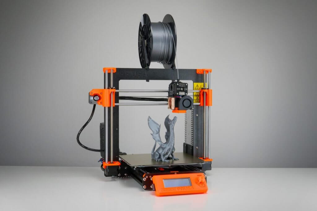
FDM vs SLA – 2018 3D Printing Technology Shootout
Reading Time: 7 minutesCheck out our FDM vs SLA Shootout. We simply explain the differences between these 3D printing technologies, and which to use for which application. FDM vs SLA: Explained The Prusa i3 MK3 is one of the finest consumer 3D printers you can get. It uses FDM technology to get things printed. (Source: ALL3DP)…
-

STL File Format (3D Printing) – Simply Explained
Reading Time: 18 minutesWhat is an STL file? What is it good for? How does it work? We simply explain the STL file format for 3D printing in depth. Here’s a primer on what they are and how they work, the advantages and disadvantages of their use, plus alternative file formats to consider. In this…
-

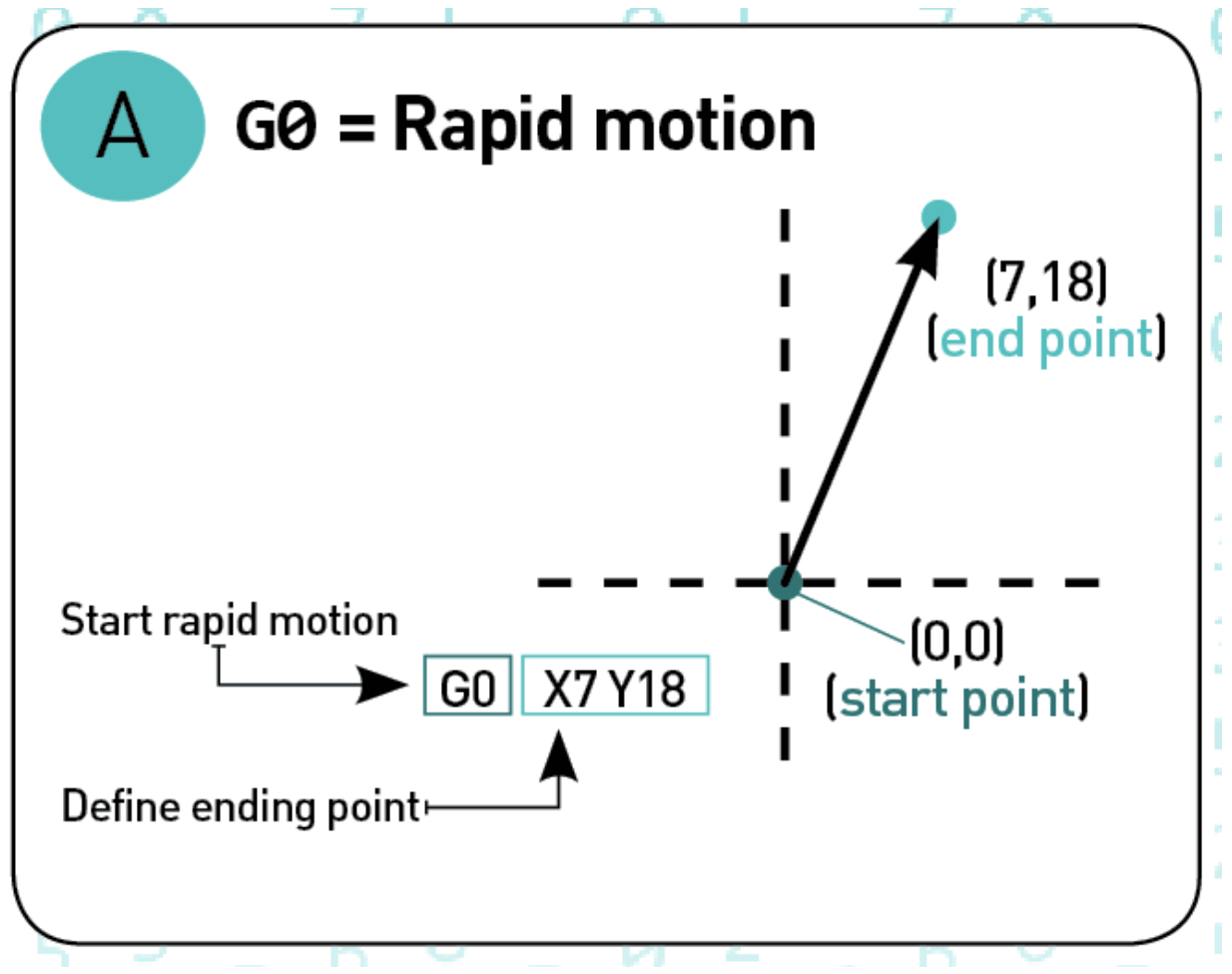
G-Code Commands – Simply Explained
Reading Time: 28 minutesG-code is the programming language of your 3D printer. In this tutorial, you’ll easily learn all G-Code commands. Using G-code, a computer tells a printer when, where, how to move and how much to extrude throughout the entire print process. If you have never dealt with it so far, that’s normal. Slicers…
-

8 Most Common 3D File Formats – Simply Explained
Reading Time: 24 minutesWhich 3D file formats are there? How do they compare? What should you use? We simply explain the 8 most common 3D file formats used today: STL, OBJ, FBX, COLLADA, 3DS, IGES; STEP, and VRML/X3D. A 3D file format is used for storing information about 3D models. You may have heard of the most…
-

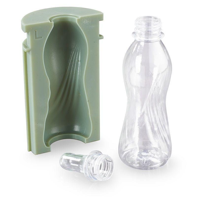
Blow Molding Technology Guide
Reading Time: 6 minutesBlow Molding (also: Blow moulding) and the molding process of polymers is one of the pillars of industrial manufacturing. Without this technology, we wouldn’t have access to cheap glass or plastic bottles or mass-manufactured hollow containers. Blow molding allows industry players to produce parts and containers fast and cheap in high quantities. But…