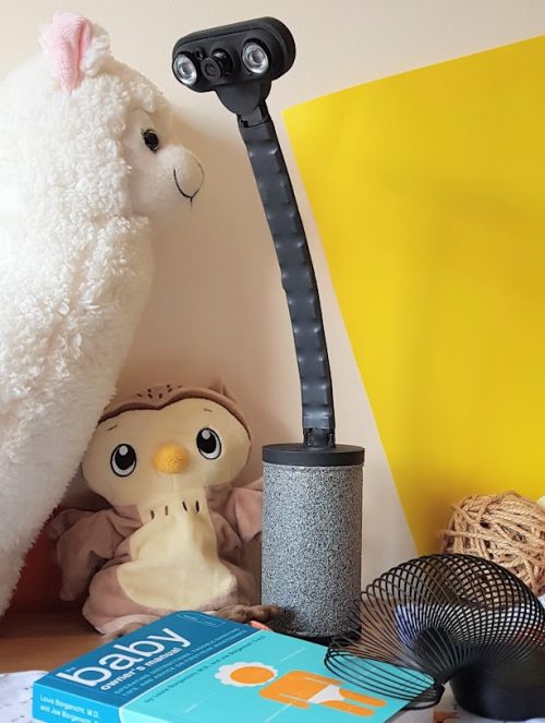
Kategorie: Linux

  • Enviro pHAT Raspberry Pi review

    Enviro pHAT Raspberry Pi review

    Reading Time: 2 minutes

    See also: Enviro + review

    The Enviro (£28/$30. Pimoroni)also features the same slimline pHAT form factor to match the size of a Raspberry Pi Zero, although it can be used with any Raspberry Pi model.

    Sensing the world

    The Enviro’s BME280 weather sensor monitors temperature, barometric pressure, and humidity. As on the Enviro +, this has been positioned at the left edge of the board, away from Raspberry Pi’s CPU, and there’s even a little smile-shaped slot around it to help reduce heat radiated through the board. Even so, you’ll need to adjust its temperature reading for accuracy (by measuring that of the CPU itself and deducting a factor of it).

    A smartphone-style LTR-559 light and proximity sensor detects the ambient light level and also proves handy as a substitute for a push-button when you put your finger on it. The board’s tiny MEMs microphone measures sound levels, useful for monitoring noise pollution, and can also be used to record audio.

    At the time of writing, most of the code examples provided with the Python library are aimed at the Enviro + Air Quality board. However, it’s easy to edit the code for missing sensors from the all-in-one example to get it showing rolling graphs for temperature, pressure, humidity, and light level on the LCD. There are also a couple of examples that make use of the mic to plot noise levels and frequencies.

    If you don’t need to test air quality and just want a simple environmental sensor with a built-in display, the Enviro is ideal. The light sensor could also come in handy for use in IoT setups, such as to trigger your lights to come on when the light level falls below a certain level.

    If you also require motion/direction sensing, the original Enviro pHAT is still available (albeit without the mini LCD).

    The reverse of the Enviro for Raspberry Pi

    Specs

    • Built-in sensors: BME280 temperature/pressure/humidity, LTR559 light/proximity, SPH0645LM4H-B noise

    • Display: 0.96-inch colour LCD (160×80)

    • Dimensions: 65×30×8.5 mm

    Verdict

    Lacks the gas sensor of the Enviro + Air Quality board, but features the same mini LCD screen to display your environmental data without a monitor.

    8/10

  • How to set up and use your brand-new Raspberry Pi

    How to set up and use your brand-new Raspberry Pi

    Reading Time: 5 minutes

    If you’re reading this, it’s probably because you bagged yourself a brand-new Raspberry Pi for Christmas, and you’re wondering what you should do next.

    Well, look no further, for we’re here to show you the ropes. So, sit back, pull on a pair of those nice, warm socks that you found in your stocking, top up your eggnog, and let’s get started.

    Do I need an operating system?

    Unless your Raspberry Pi came in a kit with a preloaded SD card, you’ll need to download an operating system. Find a microSD card (you may have one lurking in an old phone) and click here to download the latest version of Raspbian, our dedicated Raspberry Pi operating system.

    To get Raspbian onto the microSD card, use free online software such as Etcher. Here’s a video from The MagPi magazine to show you how to do it.

    Use Etcher to install operating systems onto an SD card

    Lucy Hattersley shows you how to install Raspberry Pi operating systems such as Raspbian onto an SD card, using the excellent Etcher. For more tutorials, check out The MagPi at http://magpi.cc ! Don’t want to miss an issue? Subscribe, and get every issue delivered straight to your door.

    Turn it on!

    Here, this video should help:

    How to set up your Raspberry Pi || Getting started with #RaspberryPi

    Learn #howto set up your Raspberry Pi for the first time, from plugging in peripherals to setting up #Raspbian.

    Insert your microSD card into your Raspberry Pi. The microSD card slot should be fairly easy to find, and you need to make sure that you insert it with the contact side facing the board. If you feel like you’re having to force it in, you have it the wrong way round.

    Next, plug your HDMI cable into the Raspberry Pi and your chosen HDMI display. This could be a computer monitor or your home television.

    If you’re using a Raspberry Pi Zero or Raspberry Pi Zero W, you’ll need a mini HDMI to HDMI cable or adapter.

    If you’re using a Raspberry Pi 4, you’ll need a micro HDMI to HDMI cable or adapter.

    Raspberry Pi official keyboard

    Next, plug in any peripherals that you want to use, such as a mouse or keyboard.

    Lastly, plug your power cable into your Raspberry Pi. This is any standard micro USB cable (if you have an Android phone, check your phone charger!), or a USB-C power cable if you’re using the Raspberry Pi 4.

    Most kits will come with all of the cables and adapters that you need, so look in the box first before you start rummaging around your home for spare cables.

    Once the power cable is connected, your Raspberry Pi will turn on. If it doesn’t, check that your SD card is inserted correctly and your cables are pushed in fully.

    Still in doubt? Here’s Sally Le Page with more:

    How to use a Raspberry Pi ft. Dr Sally Le Page

    What is a Raspberry Pi and what do you need to get started? Our ‘How to use a Raspberry Pi’ explainer will take you through the basics of your #RaspberryPi, and how you can get hands-on with Raspbian and #coding language tools such as Scratch and Mu, with our host, Dr Sally Le Page.

    Once on, the Raspberry Pi will direct you through a setup process that allows you to change your password and connect to your local wireless network.

    And then, you’re good to go!

    Now what?

    Now what? Well, that depends on what you want to do with your Raspberry Pi.

    Many people use their Raspberry Pi to learn how to code. If you’re new to coding, we suggest trying out a few of our easy online projects to help you understand the basics of Scratch — the drag-and-drop coding platform from MIT — and Python — a popular general-purpose programming language and the reason for the “Pi” in Raspberry Pi’s name.

    Maybe you want to use your Raspberry Pi to set up control of smart devices in your home, or build a media centre for all your favourite photos and home movies. Perhaps you want to play games on your Raspberry Pi, or try out various HATs and add-ons to create fun digital making projects.

    Sally Le Page

    Whatever you want to do with your Raspberry Pi, the internet is full of brilliant tutorials from the Raspberry Pi Foundation and online creators.

    Some places to start

    Get involved with the Raspberry Pi Foundation

    From community events and magazines to online learning and space exploration – there are so many ways to get involved with the Raspberry Pi Foundation.

    The Raspberry Pi community is huge, and spreads across the entire globe, bringing people together to share their love of coding, digital making, and computer education. However you use your Raspberry Pi, know that, by owning it, you’ve helped the non-profit Raspberry Pi Foundation to grow, bringing more opportunities to kids and teachers all over the world. So, from the bottom of our hearts this festive season, thank you.

    We can’t wait to see what 2020 brings!

    Website: LINK

  • Organnery pipe organ

    Organnery pipe organ

    Reading Time: 3 minutes

    Raphaël tell us that he increasingly found components for first-generation digital pipe organs – many of which are installed in churches across the world – to be either obsolete, expensive, or simply unobtainable, threatening to consign many an instrument to the scrap-heap.

    The solution has been Organnery, a project to to strip the organs of their old electronics and replace them with something new. “After some thoughts and calculations, we came up with a method that would retain the console, keyboard, and controls and instead make use of a small, affordable, and efficient single-board computer,” he says.

    The chosen device was a Raspberry Pi, selected because of its worldwide availability, strong development community, and affordable price. It offered a perfect way of bringing pipe organs back to life so that they can be played as before, while allowing modern options such as a touchscreen.

    “There are lots of good HATs available covering sound output, MIDI, and control interfaces,” says Daniel James, boss of 64 Studio, the company tasked with creating the software.

    Digital organs have been used in place of pipe organs within churches for a while, but damp and the scarcity of spare parts mean they’re not lasting as long

    Fine tuning the Organnery

    As such, Daniel and colleague Chris Obbard began to work on a customised Debian GNU/Linux image called Organnery (GitHub link) that made use of the open-source classical organ modelling software Aeolus and Raspberry Pi’s capabilities. With eleven different temperaments, variable tuning, three or more manuals, and a pedal board, as well as MIDI in/out control and the flexibility to play different sounds, a personalised experience is possible.

    “Organnery needed to be set up as a single-use appliance, and the requirements came directly from the organists we’ve been working with to refine the system,” Daniel says. “We made adjustments to the Aeolus source code as well as to supporting programs. These included Mididings, a scriptable MIDI router and processor written in Python.”

    Daniel also created minimal system images based on Debian Buster using Dibby, which is a collection of scripts that leverage the distro’s packaging tools. “This approach was a far leaner and more reproducible way to build appliances than starting from a standard image and stripping the system down,” Daniel says.

    The Aeolus software allows a collection of stops to be saved to a USB memory stick for each organist

    Retro hits

    So what’s the verdict? “Organnery offers a major sound upgrade since the sound produced by the Aeolus software is of a much better quality than digital electronics from the 1980s,” Raphaël says. “It gives the organ player access to new ‘pipes’ and complete control over sound placement in space, from a standard stereo system up to 3D Ambisonic diffusion.”

    Most Organnery systems are being retro-fitted into existing organs, but the system can be built from scratch using standard and affordable MIDI hardware. “Some of the smaller organs made for the domestic market have a five-pin MIDI Out socket and can be obtained for next to nothing,” Daniel explains. “Aeolus and Organnery can also make learning the classical organ much more accessible than it has been in the past.”

    Even so, bringing organs back to life, complete with the original woodwork and physical controls, is perhaps most satisfying. “Church organ consoles are also often made of expensive hardwoods so we are saving trees,” Daniel says. For organists used to the age-old interface of their instruments, that’s sure to be extra music to their ears.

    The MIDI switches of an organ are being retro-fitted with new electronics, powered by Raspberry Pi

  • Full control of your TV using Alexa and Arduino IoT Cloud

    Full control of your TV using Alexa and Arduino IoT Cloud

    Reading Time: 2 minutes

    Full control of your TV using Alexa and Arduino IoT Cloud

    Arduino TeamDecember 23rd, 2019

    We’re excited to announce that the official Arduino Amazon Alexa skill now supports television control.

    You can now securely connect your TV set to Alexa using Arduino IoT Cloud and a few lines of code.

    Here are some of the features which will be available to you:

    • Power on/off
    • Switch channel
    • Volume up/down/mute
    • Switch input sources

    The easiest way to operate any kind of television is to act as if we were its very own clicker. In order to do so, we’ll show you how to capture the commands from the remote and play them back via Arduino (the TV will never know what hit it).

    We’ll then create an Arduino IoT Cloud Thing with a TV property, and adapt the generated code to our needs. Finally, we’ll configure Alexa to access and control our TV.

    Afterwards, we’ll be able to ask things such as:

    • “Alexa, turn the volume up on TV.”
    • “Alexa, mute TV” or “Alexa, unmute TV.”
    • “Alexa, next channel on TV.”

    The complete step-by-step guide is available on our Project Hub.

    Share your creativity with us! Our community means a lot to us, so we would love to see what you create. Make sure you document and post your amazing projects on the Arduino Project Hub and use the #ArduinoAlexa hashtag to make it discoverable by everyone!

    Have fun playing with Alexa and IoT Cloud. If you have questions and/or build this project, let us know in the comments below.

    Website: LINK

  • HeyTeddy is a conversation-based prototyping tool for Arduino

    HeyTeddy is a conversation-based prototyping tool for Arduino

    Reading Time: 2 minutes

    Programming an Arduino to do simple things like turn on an LED or read a sensor is easy enough via the official IDE. However, think back to your first experiences with this type of hardware. While rewarding, getting everything set up correctly was certainly more of a challenge, requiring research that you now likely take for granted.

    To assist with these first steps of a beginner’s hardware journey, researchers at KAIST in South Korea have come up with HeyTeddy, a “conversational test-driven development [tool] for physical computing.” 

    As seen in the video below, HeyTeddy’s voice input is handled by an Amazon Echo Dot, which passes these commands through the cloud to a Raspberry Pi. The system then interacts with the physical hardware on a breadboard using an Arduino Uno running Firmata firmware, along with a 7” 1024 x 600 LCD touchscreen for the GUI. Once programmed, code can be exported and used on the board by itself.

    Those wishing to learn more can check out the entire research paper here

    [youtube https://www.youtube.com/watch?v=GUtUtIBBJ74?feature=oembed&w=500&h=281]

    HeyTeddy is a conversational agent that allows users to program and execute code in real-time on an Arduino device without writing actual code but instead operating it through dialogue. This conversation can either be based on voice or text (through a Web chat). Commands spoken to HeyTeddy are parsed, interpreted, and executed in real-time, resulting in physical changes to the hardware. For example, the “write high” command configures an I/O pin to behave as a digital output with its internal state set to high (e.g., a 5V logic level), making driving an LED possible. Hence, the user does not need to write any code, compile it, deal with errors, and manually upload it on the hardware.

    Furthermore, HeyTeddy supervises the user’s choices, preventing incorrect logic (e.g., writing an analog value to a digital pin), guiding the user through each step needed to assemble the circuit, and providing an opportunity to test individual components through separate unit tests without interrupting the workflow (i.e., TDD functionalities). Finally, the user has the option of exporting the issued commands as a written code for Arduino (i.e., an Arduino sketch in C++, ready for upload). 

    Website: LINK

  • arduino-cli 0.7.0 is out!

    arduino-cli 0.7.0 is out!

    Reading Time: < 1 minute

    arduino-cli 0.7.0 is out!

    Arduino TeamDecember 20th, 2019

    Our dev team is about to kick off their holiday breaks, but not without sharing some exciting news first: the release of arduino-cli 0.7.0!

    Highlights include:

    • Notarization compliance for macOS
    • Some breaking changes:
      • Remove Sketchbook concept, introduce user data folder
      • “lib list” now returns an empty JSON array when there are no libraries installed
      • Change configuration file format
      • Terminate daemon command when parent process exits; added “–daemonize” flag to keep old behavior
    • Added a lot of bugfixing and minor features

    The latest version will be available on the other distribution channels (i.e. Homebrew) in the coming days. Stay tuned!

    Website: LINK

  • Raspberry Pi 3 baby monitor | Hackspace magazine #26

    Raspberry Pi 3 baby monitor | Hackspace magazine #26

    Reading Time: 7 minutes

    You might have a baby/dog/hamster that you want to keep an eye on when you’re not there. We understand: they’re lovely, especially hamsters. Here’s how HackSpace magazine contributor Dr Andrew Lewis built a Raspberry Pi baby cam to watch over his small creatures…

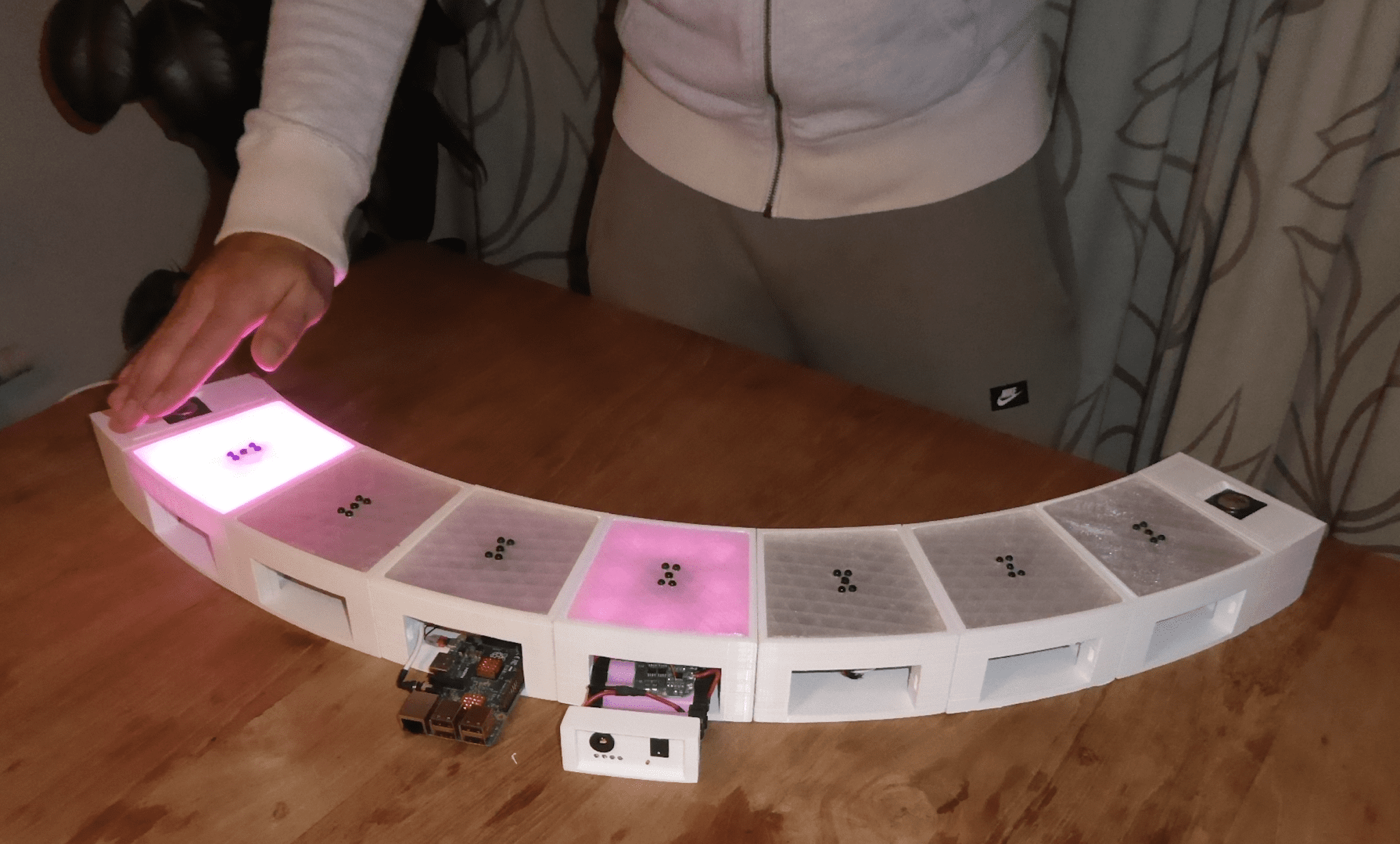
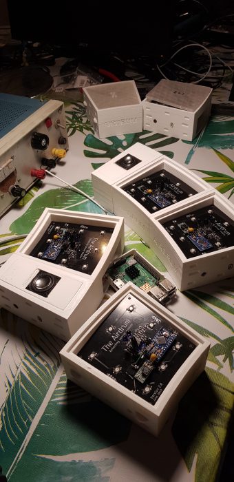
    When a project is going to be used in the home, it pays to take a little bit of extra time on appearance

    Wireless baby monitors

    You can get wireless baby monitors that have a whole range of great features for making sure your little ones are safe, sound, and sleeping happily, but they come with a hefty price tag.

    In this article, you’ll find out how to make a Raspberry Pi-powered streaming camera, and combine it with a built-in I2C sensor pack that monitors temperature, pressure, and humidity. You’ll also see how you can use the GPIO pins on Raspberry Pi to turn an LED night light on and off using a web interface.

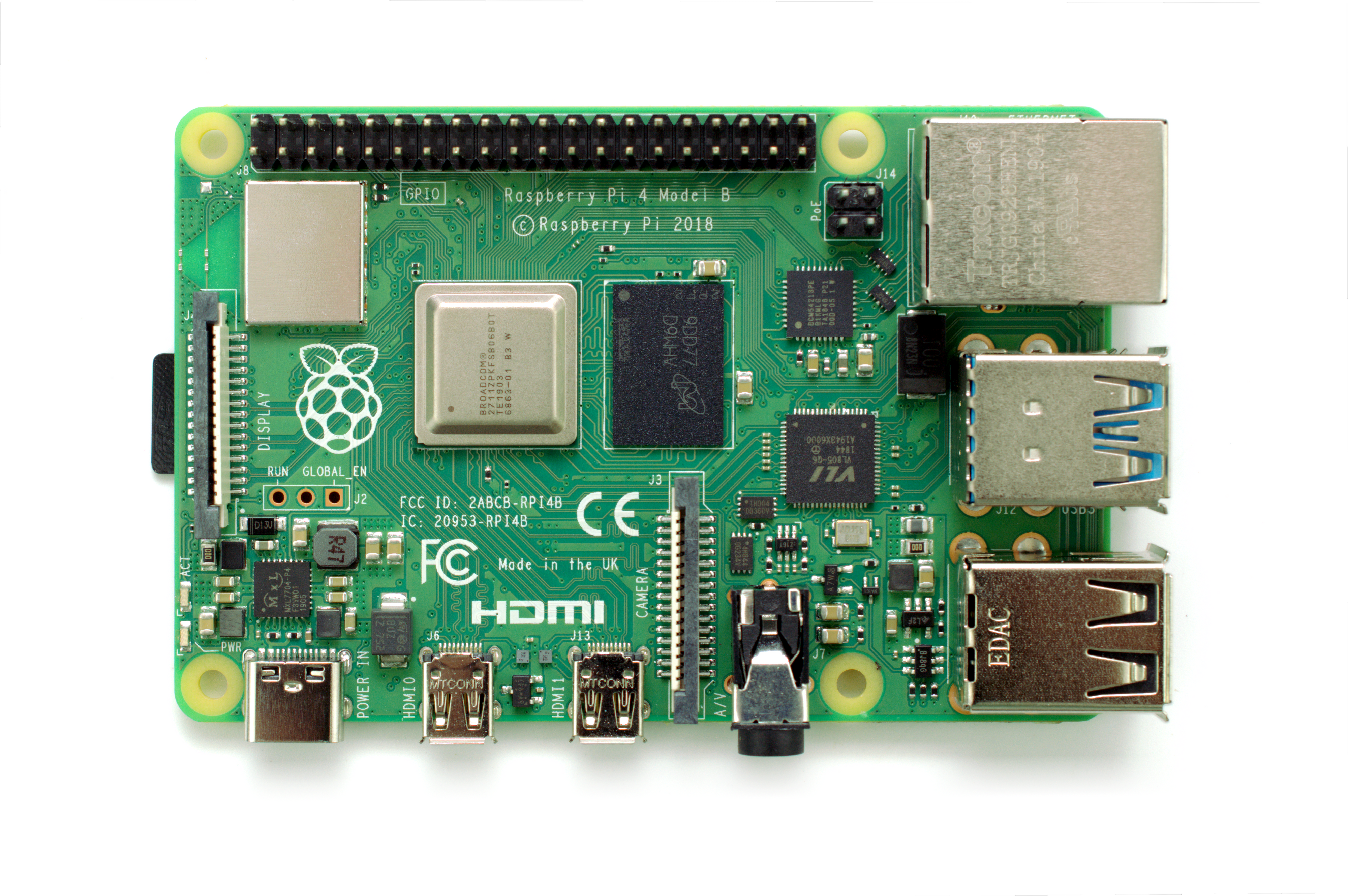
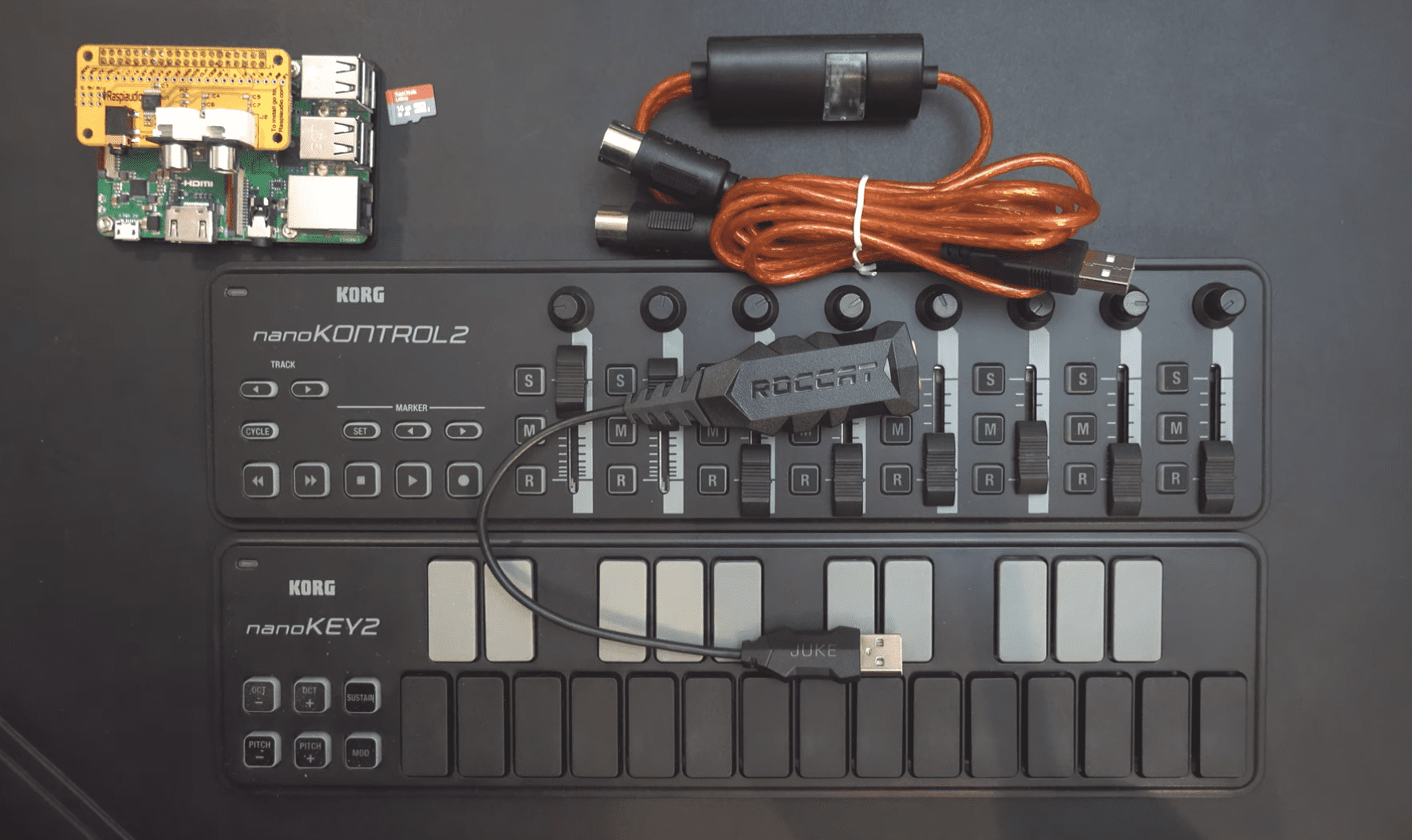
    The hardware for this project is quite simple, and involves minimal soldering, but the first thing you need to do is to install Raspbian onto a microSD card for your Raspberry Pi. If you’re planning on doing a headless install, you’ll also need to enable SSH by creating an empty file called SSH on the root of the Raspbian install, and a file with your wireless LAN details called wpa_supplicant.conf.

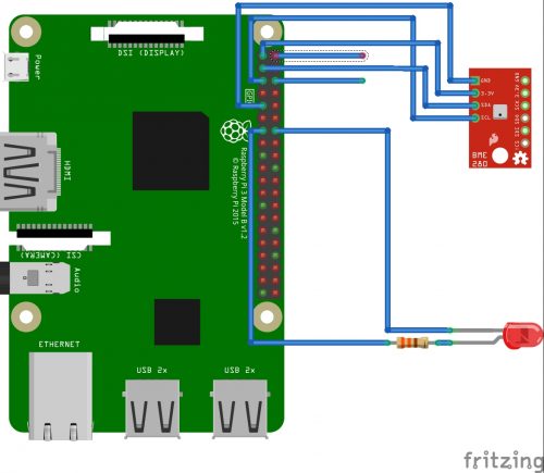
    You can download the code for this as well as the 3D-printable files from our GitHub. You’ll need to transfer the code to the Raspberry Pi. Next, connect the camera, the BME280 board, and the LEDs to the Raspberry Pi, as shown in the circuit diagram.

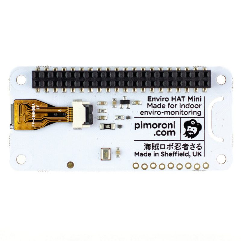
    The BME280 module uses the I2C connection on pins 3 and 5 of the GPIO, taking power from pins 1 and 9. The LEDs connect directly to pins 19 and 20, and the camera cable fits into the camera connector.

    Insert the microSD card into the Raspberry Pi and boot up. If everything is working OK, you should be able to see the IP address for your device listed on your hub or router, and you should be able to connect to it via SSH. If you don’t see the Raspberry Pi listed, check your wireless connection details and make sure your adapter is supplying enough power. It’s worth taking the time to assign your Raspberry Pi with a static IP address on your network, so it can’t change its IP address unexpectedly.

    Smile for Picamera

    Use the raspi-config application to enable the camera interface and the I2C interface. If you’re planning on modifying the code yourself, we recommend enabling VNC access as well, because it will make editing and debugging the code once the device is put together much easier. All that remains on the software side is to update APT, download the babycam.py script, install any dependencies with PIP, and set the script to run automatically. The main dependencies for the babycam.py script are the RPi.bme280 module, Flask, PyAudio, picamera, and NumPy. Chances are that these are already installed on your system by default, with the exception of RPi.bme280, which can be installed by typing sudo pip3 install RPi.bme280 from the terminal. Once all of the dependencies are present, load up the script and give it a test run, and point your web browser at port 8000 on the Raspberry Pi. You should see a webpage with a camera image, controls for the LED lights, and a read-out of the temperature, pressure, and humidity of the room.

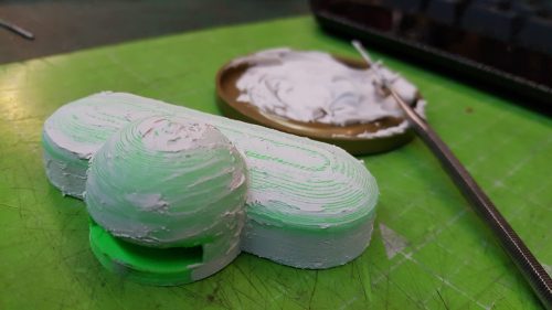
    Finishing a 3D print by applying a thin layer of car body filler and sanding back will give a much smoother surface. This isn’t always necessary, but if your filament is damp or your nozzle is worn, it can make a model look much better when it’s painted

    The easiest way to get the babycam.py script to run on boot is to add a line to the rc.local file. Assuming that the babycam.py file is located in your home directory, you should add the line python3 /home/pi/babycam.py to the rc.local file, just before the line that reads exit 0. It’s very important that you include the ampersand at the end of the line, otherwise the Python script will not be run in a separate process, the rc.local file will never complete, and your Raspberry Pi will never boot.

    Tinned Raspberry Pi

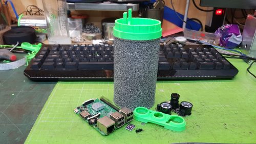
    With the software and hardware working, you can start putting the case together. You might need to scale the 3D models to suit the tin can you have before you print them out, so measure your tin before you click Print. You’ll also want to remove any inner lip from the top of the can using a can opener, and make a small hole in the side of the can near the bottom for the USB power cable. Next, make a hole in the bottom of the can for the LED cables to pass through.

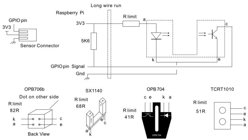
    If you want to add more than a couple of LEDs (or want to use brighter LEDs), you should connect your LEDs to the power input, and use a transistor on the GPIO to trigger them

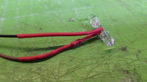
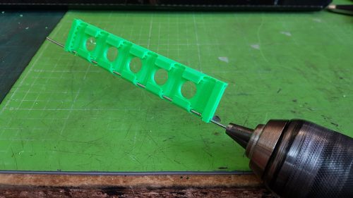
    If you haven’t already done so, solder appropriate leads to your LEDs, and don’t forget to put a 330 Ω resistor in-line on the positive side. The neck of the camera is supported by two lengths of aluminium armature wire. Push the wire up through each of the printed neck pieces, and use a clean soldering iron to weld the pieces together in the middle. Push the neck into the printed top section, and weld into place with a soldering iron from underneath. Be careful not to block the narrow slot with plastic, as this is where the camera cable passes up through the neck and into the camera.

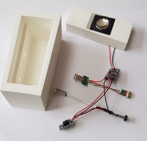
    You need to mount the BME280 so that the sensor is exposed to the air in the room. Do this by drilling a small hole in the 3D-printed top piece and hot gluing the sensor into position. If you’re going to use the optional microphone, you can add an extra hole and glue the mic into place in the same way. A short USB port extender will give you enough cable to plug the USB microphone into the socket on your Raspberry Pi

    Paint the tin can and the 3D-printed parts. We found that spray blackboard paint gives a good effect on 3D-printed parts, and PlastiKote stone effect paint made the tin can look a little more tactile than a flat colour. Once the paint is dry, pass the camera cable up through the slot in the neck, and then apply the heat-shrink tubing to cover the neck with a small gap at the top and bottom. Connect the camera to the top of the cable, and push the front piece on to hold it into place. Glue shouldn’t be necessary, but a little hot glue might help if the front parts don’t hold together well.

    Push the power cable through the hole in the case, and secure it with a knot and some hot glue. Leave enough cable free to easily remove the top section from the can in future without stressing the wires.

    If you’re having trouble getting the armature wire through the 3D-printed parts, try using a drill to help twist the wire through

    This is getting heavy

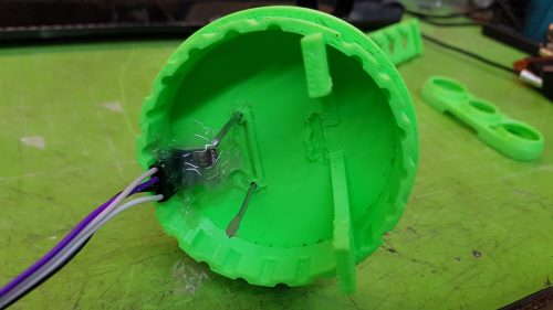
    Glue the bottom section onto the can with hot glue, and hot-glue the LEDs into place on the bottom, feeding the cable up through the hole and into the GPIO header. This is a good time to hot-glue a weight into the bottom of the can to improve its stability. I used an old weight from some kitchen scales, but any small weight should be fine. Finally, fix the Raspberry Pi into place on the top piece by either drilling or gluing, then reconnect the rest of the cables, and push the 3D-printed top section into the tin can. If the top section is too loose, you can add a little bit of hot glue to hold things together once you know everything is working.

    With the right type of paint, even old tin cans make a good-looking enclosure
    for a project

    That should be all of the steps complete. Plug in the USB and check the camera from a web browser. The babycam.py script includes video, sensors, and light control. If you are using the optional USB microphone, you can expand the functionality of the app to include audio streaming, use cry detection to activate the LEDs (don’t make the LEDs too stimulating or you’ll never get a night’s sleep again), or maybe even add a Bluetooth speaker and integrate a home assistant.

    HackSpace magazine issue 26

    HackSpace magazine is out now, available in print from your local newsagent, the Raspberry Pi Store in Cambridge, and online from Raspberry Pi Press.

    If you love HackSpace magazine as much as we do, why not have a look at the subscription offers available, including the 12-month deal that comes with a free Adafruit Circuit Playground!

    And, as always, you can download the free PDF here.

    Website: LINK

  • ZX Spectrum Next Raspberry Pi project showcase

    ZX Spectrum Next Raspberry Pi project showcase

    Reading Time: 4 minutes

    “For me, the goal has been to encourage a new generation of bedroom coders,” says legendary games developer Jim Bagley, who is among a group of Spectrum fans behind the project. Jim has been programming games professionally for the past 31 years and is a key member of the specnext.com team dedicated to bringing back the ZX Spectrum.

    Jim Bagley is a legendary games developer and ones of the leading lights behind bringing back the ZX Spectrum

    With 3113 Kickstarter backers handing over £723,390 in cash, many others potentially share that dream.

    Work has certainly progressed well. “When the Next was first announced three years ago, it was intended to be a normal Spectrum with an SD card and a Raspberry Pi Zero as an extender,” Jim explains. “Raspberry Pi was going to be used to add extra features such as hardware sprites and hardware scrolling so that newcomers would find it easier to code the computer and get the wow factor of getting something running instantly on the screen.”

    During the Kickstarter campaign, however, a large field-programmable gate array (FPGA) was announced for the Next – a configurable integrated circuit which allowed the hardware sprites, scrolling, and other advanced features to be incorporated within the machine itself. “It freed up Raspberry Pi Zero to do something else,” Jim says. So the developers began to play around.

    It will work with CRT and VGA monitors, as well as more modern screens, thanks to the support of a HDMI output

    Load and run

    One of the initial ideas was to recreate the feel of loading a game from tape – generating the series of scratchy, beepy, high-pitched noises which could be heard as a program was ingested into the computer. On the original hardware, this was accompanied by a loading image slowly building on the screen and animated stripy borders.

    Rather than have Next users connect a cassette deck, the developers had a cunning plan. “We thought it would be a good idea to have commands sent back and forth between the Next and Raspberry Pi Zero,” Jim says. This developed into a tool allowing a TZX file (a format that stores an exact copy of a ZX Spectrum tape) to be uploaded from an SD card to Raspberry Pi Zero. By sending it back down to the new-gen Speccy through an audio-in pin, the Next would be fooled into thinking it’s loading a cassette. “It gives the original feeling of loading from tape,” Jim affirms.

    The ZX Spectrum Next contains a Z80 processor on an FPGA, 1MB of RAM expandable to 2MB,
hardware sprites, 256 colours, RGB/VGA/HDMI video output, and three AY-3-8912 audio chips

    Are you there, SID?

    Having a Raspberry Pi Zero accompanying the Next has also enabled other audio delights. A Sound Interface Device (SID) emulator has been developed that allows audio created for Commodore’s SID programmable sound generator chip to be played on the Next.

    It will also be possible to enjoy Atari ST audio files and tunes created using music trackers on the Commodore Amiga. “We can send the audio through a GPIO pin and it goes straight to the FPGA, where it’s mixed with the audio of the Next,” Jim explains. To achieve all of this, the developers have used DietPi to create a new OS called NextPi. “It remains a fully functioning Raspberry Pi Zero that is running at the same time as the Next, but we wanted the Next to be more in control.”

    Games made specially for the Next are saved as .NEX files which load directly to the computer via a
SD card. Since the games are 768kB in size (or 1792kB for the 2MB models), it would take too long to route them via Raspberry Pi Zero

    The most recent extra use for the Next’s Raspberry Pi Zero is the ability to connect the latter to its own display. “It’s possible to send screens to Raspberry Pi Zero so that you can have a dual screen,” Jim says. “This means you could have a game being played on the Next, with a global map or stats shown via Raspberry Pi Zero.”

    The team is now looking to get USB controllers to work via Raspberry Pi Zero, allowing them to be read by the Next. “We’d also like Raspberry Pi Zero to help with 3D maths so you can take vertices, have them rotated, and passed back,” Jim says. In the meantime, the team is readying the new computer for a January release and a new Kickstarter is being planned for those who didn’t pledge the first time around. We’re certainly looking forward to seeing where it – and RaspberryPi – goes next.

    Rather than simply emulate the Spectrum, the Next uses a field-programmable gate array chip that acts as a Z80 processor with the addition of advanced features

    Raspberry Pi loading

    1. Games in the file format TZX – a tape format used for preservation purposes – need to be saved on to an SD card and inserted into the ZX Spectrum Next. 

    Games are installed on the ZX Spectrum Next from an SD Card

    2. A game can then be selected via the Next computer’s built-in Browser mode. Raspberry Pi Zero will be instructed to load the game’s data from the SD card.

    Select a game in the ZX Spectrum Next’s Browser mode and Raspberry Pi Zero instructs it to load from the SD card.

    3. Raspberry Pi Zero sends the data back to the ZX Spectrum Next as audio and this generates the once-familiar loading noise and loading screen ahead of the game running.

    Raspberry Pi sends data to the ZX Spectrum as audio, resulting in the familiar electronic loading sounds of 80s computer games

    Looking for some more retro gaming joy? You could always: code your own retro games console, build your own retro game with PICO-8, indulge in an entire issue of The MagPi dedicated to retro gaming or this incredible hardback ‚Code The Classics‘ guide, brand-new from Raspberry Pi Press for a more £12?

  • Hands-free Raspberry Pi Airdrum | The MagPi 89

    Hands-free Raspberry Pi Airdrum | The MagPi 89

    Reading Time: 4 minutes

    We’re always going to beat the drum for projects that seek to improve the lives of people with disabilities. That’s why we fell in love with the Airdrum, which was created to allow anyone, in particular people with disabilities, to play a musical instrument.

    The Airdrum – speaker and MIDI song demo

    This video demonstrates the speaker functionality with playing a song from a midi file on the Raspberry pi using Fluidsynth. (The hand movement is just for fun) The Airdrum is powered by a power supply for demonstration purposes.

    Raspberry Pi Airdrum

    Designed by two Dutch electrical engineering students, Alessandro Verdiesen and Luuk van Kuijk, the project came to life during their first year at university. “We aimed to develop a musical instrument that could be used to generate music by moving,” explains Alessandro, who has recently been working on a fully modular version 2.0.

    After speaking with therapists and health care institutions, the pair decided to make a drum that could be played by moving objects above a set of panels and they put Raspberry Pi at its heart. “The basic functionality of the Airdrum is to detect the distance of an object above each connected panel and play a sound,” says Alessandro. “These panels contain IR distance sensors and coloured LEDs for visual feedback.”

    Sorting the bass-ics

    From the outset, Alessandro and Luuk needed their project to be accessible, affordable, adjustable and, in the latest iteration, modular, with each drummable section containing an Arduino Mini, an IR sensor, and LEDs. They also wanted the instrument to have a broader appeal and be suitable for everybody, including professional musicians, so it had to sound as good as it played.

    “We needed it to be as versatile as it can be and allow people to choose custom sounds, colours, and lights while being a standalone instrument and a multi-purpose input/output device,” Alessandro reveals. To make it easy to place the modules together, they used magnetic connections between the panels. This allowed them to be placed together in various configurations, with a minimum of two per Airdrum.

    These speaker modules can bookend the sensor panels, although the sound can be outputted via the Raspberry Pi to a different sound system too

    With a structured plan that divided milestones into electrical, mechanical, and software components, the pair used 3D printing for the enclosure, which allowed rapid prototyping for quick interactions. They used speaker panels to bookend the modules for auditive feedback.

    Panel beating

    Each of the panels includes a buck converter so that the current through the connectors can be drawn to a minimum. The master module panel contains Raspberry Pi 3 running custom programs written in C and Python, as well as the free, open-source software synthesiser FluidSynth. It connects to the other panels through I2C, constantly polling the panels for their measurements and for the configuration of their colour.

    “If an object has been detected, the Raspberry Pi generates a sound and outputs it on the AUX audio jack,” says Alessandro. “This output is then used by the mono D-class amplifiers in the speaker panels to make the tones audible.”

    Custom-made Airdrum detecting modules fit snugly into their 3D-printed cases and can be arranged in a full circle if you have enough of them

    The pair chose Raspberry Pi because of its versatility and technical prowess. “The Airdrum needed something powerful enough to run software to generate audio through MIDI using the input from the panels and the Raspberry Pi is a great universal and low-cost development board with integrated DAC for audio,” explains Alessandro. “It also has a I2C bus to act as a data transfer master unit and they’re compact enough to fit inside of the casing. The Raspberry Pi enables easy implementation of future upgrades, too.”

    Indeed, the pair want to explore the MIDI possibilities and connect the Airdrum with a smartphone or tablet. An app is being planned, as is a built-in synthesiser. “The people we have shown the Airdrum to have been very enthusiastic,” Alessandro says. “That has been very motivating.”

    Read The MagPi for free!

    There’s loads more amazing projects and tutorials in The MagPi #89, out today, including our 50 tools and tips for makers, and a huge accessory guide! You can get The MagPi #89 online at our store, or in print from the Raspberry Pi Store in Cambridge and all good newsagents and supermarkets. You can also access The MagPi magazine via our Android and iOS apps.

    Don’t forget our amazing subscription offers either, which include a free gift of a Raspberry Pi Zero W when you subscribe for twelve months.

    And, as with all our Raspberry Pi publications, you can download the free PDF from our website.

    Website: LINK

  • 50 Raspberry Pi tips and tools in The MagPi magazine issue 89

    50 Raspberry Pi tips and tools in The MagPi magazine issue 89

    Reading Time: 2 minutes

    A lot of projects need specific tools, and there’s a lot out there to choose from. Raspberry Pi maker Mark Vanstone takes a look at the 50 best physical and digital tools you can use to build projects.

    Click here to buy The MagPi magazine issue #89

    50 Raspberry Pi 4 tips & tools

    Raspberry Pi kit & gadget guide

    Quickly do more with your Raspberry Pi with kits and accessories. Our guide to the best add-ons, HATs, starter kits, robot builds and accessories has everything you need.

    Raspberry Pi kit & gadget guide

    Add internet to a classic computer

    Missing the days of dial-up? Build an interface to the modern world for an old computer (an Atari ST, in our case) using a RS232 receiver.

    Add internet to a classic computer

    Design a 3D printer pendant with BlocksCAD

    BlocksCAD is a 3D model editor that runs just fine on the faster Raspberry Pi 4. In this tutorial we look at how to use this Scratch-like language to design a pendant for a 3D printer.

    Design a 3D printer pendant

    Aquatic Mini Observation System

    We’ve got the best community projects every month. Murray Lowery-Simpson used Raspberry Pi at the heart of this solar-powered, autonomous boat that measures water quality.

    Aquatic Mini Observation System

    Cheeseborg

    What could be more entertaining than this AI-powered grilled-cheese sandwich machine? We take an in-depth look at this capable cheese-making robot.

    Cheeseborg

    Plus! Win one of five Raspberry Pi and black Official Case kits.

    The MagPi is available as a free digital download, or you can purchase a print edition online or in stores.

  • Build your own tracking and GoTo mount for DSLR astrophotography

    Build your own tracking and GoTo mount for DSLR astrophotography

    Reading Time: < 1 minute

    Build your own tracking and GoTo mount for DSLR astrophotography

    Arduino TeamDecember 18th, 2019

    Astrophotography can be challenging, in a large part because your subject matter — or your base, the Earth rather — is constantly moving. In order to take excellent long exposures of far-off objects, Redditor intercipere came up with a beautiful 3D-printable, star-following mount that holds and rotates a DSLR camera.

    Now intercipere can simply input the RA/DEC coordinates and the device will automatically move to a desired target in the sky.

    Motion is handled by an Arduino Uno and two small stepper motors, with a 16×2 LCD shield user interface. The rig is capable of tracking for at least four minutes, producing this photo of the Andromeda galaxy with a cheapo lens from a heavy light polluted area.

    Website: LINK

  • How to run a script at start-up on a Raspberry Pi using crontab

    How to run a script at start-up on a Raspberry Pi using crontab

    Reading Time: 2 minutes

    Do you need to run a script whenever your Raspberry Pi turns on? Here’s Estefannie to explain how to edit crontab to do exactly that.

    How to start a script at start-up on a Raspberry Pi // LEARN SOMETHING

    Do you want your Raspberry Pi to automatically run your code when it is connected to power? Then you are in the right place. In this new #LEARNSOMETHING video I show you how to make you Raspberry Pi run your script automatically when it is connected to a power source.

    Running script on startup

    While there are many ways of asking your Raspberry Pi to run a script on start-up, crontab -e is definitely one of the easiest.

    AND, as Estefannie explains (in part thanks to me bugging asking her to do so), if you create a run folder on your desktop, you can switch out the Python scripts you want to run at start-up whenever you like and will never have to edit crontab again!

    Weeeeee!

    Now go write some wonderful and inspiring festive scripts while I take a well-earned nap. I just got off a plane yet here I am, writing blog posts for y’all because I love you THAT DARN MUCH!

    A fluffy cat

    This is Teddy. Teddy is also in the video.

    And don’t forget to like and subscribe for more Estefannie Explains it All goodness!

    Website: LINK

  • Win! One of five Raspberry Pi 4 and case bundles!

    Win! One of five Raspberry Pi 4 and case bundles!

    Reading Time: < 1 minute

    Subscribe

  • Win! One of five Raspberry Pi 4 and case bundles!

    Win! One of five Raspberry Pi 4 and case bundles!

    Reading Time: < 1 minute

    Subscribe

  • Take your X-Plane 11 experience to new heights with this 3D-printed simulator

    Take your X-Plane 11 experience to new heights with this 3D-printed simulator

    Reading Time: < 1 minute

    Take your X-Plane 11 experience to new heights with this 3D-printed simulator

    Arduino TeamDecember 17th, 2019

    Apparently not satisfied with a single PC monitor, aviation enthusiast Ryan H came up with his own custom, 3D-printable cockpit setup for the Garmin G1000 avionics suite. Designed around the X-Plane 11 flight simulator, the system uses a 12.1” LCD panel for flight data along with several additional inputs, all controlled by an Arduino Mega running SimVim firmware.

    The auxiliary display/input assemblies interface with the Arduino, enabling it to handle 32 tactile switches plus one standard and five dual rotary encoders via five CD74HC4067 16-channel multiplexers.

    Build cost is around $250 per screen. 3D-print files and other information are available on Thingiverse

    [youtube https://www.youtube.com/watch?v=RXDCMxshyNw?feature=oembed&w=500&h=281]

    Website: LINK

  • Raspberry Pi capacitive-touch musical Christmas tree

    Raspberry Pi capacitive-touch musical Christmas tree

    Reading Time: 2 minutes

    What, your Christmas tree ISN’T touch-enabled?

    Capacitive Touch Christmas Tree How To | Raspberry Pi | Bare Conductive Pi Cap

    Turn your Christmas tree into a capacitive touch-interactive musical instrument using a Raspberry Pi and a Bare Conductive Pi Cap. You’ll be rocking around the Christmas tree in no time! /* Bare Conductive */ Pi Cap: https://www.bareconductive.com/shop/pi-cap/ Touch Board: https://www.bareconductive.com/shop/touch-board/ Code: https://github.com/BareConductive/picap-touch-mp3-py #RasberryPi #BareConductive #Christmas

    Using the Bare Conductive Pi Cap, Davy Wybiral hooked up his fairy lights and baubles to a Raspberry Pi. The result? Musical baubles that allow the user to play their favourite festive classics at the touch of a finger. These baubles are fantastic, and it’s easy to make your own. Just watch the video for Davy’s how-to.

    The code for Bare Conductive’s Pi Cap polyphonic touch MP3 utility can be found in this GitHub repo, and you can pick up a Pi Cap on the Bare Conductive website. Then all you need to do is hook up your favourite tree decorations to the Pi Cap via insulated wires, and you’re good to go. It’s OK if your decorations aren’t conductive: you’ll actually be touching the wires and not the ornaments themselves.

    And don’t worry about touching the wires, it’s perfectly safe. But just in this instance. Please don’t make a habit of touching wires.

    Make sure to subscribe to Davy on YouTube (we did) and give him a like for the baubles video. Also, leave a comment to tell him how great it is, because nice comments are lovely, and we should all be leaving as many of them as we can on the videos for our favourite creators.

    Website: LINK

  • 10 Best Christmas projects

    10 Best Christmas projects

    Reading Time: 3 minutes

    VR to RL

    Minecraft can be hacked with a bit of code so that you can make it do as you wish. But this also means that, via more code, it can interact with reality. David Stevens made it so changes to the Christmas tree in the game alter the lights outside. Clever!

    Hack Minecraft using code so when its Christmas lights change colour your own tree lights do too

    Advanced tree lights

    We quite like the smart lights we made ourselves, but if you want to do some serious Christmas tree hacking, we suggest taking a look at this amazing project on Instructables.

    Hack your Christmas tree lights using this incredible tutorial on Instructables

    Upgrade your office

    If you find fishing names out of a hat a bit old-fashioned, you can always have Babbage Bear choose for you. Squeeze his hand and he’ll print out a piece of paper showing who you need to buy for. There’s a £5 gift limit, though.

    Santa Babbage chooses which colleague you need to buy a present for

    Home light automation

    This is a serious amount of lights all over this house to be controlled by a Raspberry Pi. David does so using a phone to connect to Raspbian via VNC.

    How's this for a home automation hack?

    Raspberry Pi fireplace

    Some people like to turn on the fireplace video on Netflix; others prefer to create digital fires of their own. This one also does the impossible and can cycle through different colours of flame.

    Take your virtual fireplace to the next level with this flame colour-changing project

    Make a list

    A modern take on the palm readers you used to find on seaside piers, although this machine takes a more binary approach: are you naughty… or nice? Think happy thoughts.

    Do you really deserve a gift from Santa this year? The Naughty or Nice Machine will decide!

    Drop the house bass

    Another project where a house has been kitted out with full Raspberry Pi-powered lights – only this one plays music and syncs to it as well. Especially phat dubstep tracks.

    The incredible light show on this Raspberry Pi=enabled display flashes along in sync with the music

    Catch Saint Nick

    This is a fun Scratch project that allows you to go to sleep happy in the knowledge that you won’t miss Santa. Maybe you’ll find out exactly how big his sack of toys is.

    You need to be lightning fast to catch Santa delivering presents. The Santa Detector gives a helping hand

    Hack the magazine

    A couple years ago we made a little project that allowed you to turn a copy of The MagPi into a light-up Christmas card. Grab the PDF, print the cover on card, and give it a go!

    Send us your holiday projects

    Made something with Raspberry Pi for this holiday season? Send us photos on Twitter (@TheMagPi) or via email and we might feature you in the next issue!

  • Hack GraviTrax with Raspberry Pi

    Hack GraviTrax with Raspberry Pi

    Reading Time: 7 minutes

    When you get your starter set, you have to prepare the cardboard base by pushing out hexagons to leave holes to mount the tiles in. Do not discard these hexagons, because we are going to use them in our project. If you have already discarded them, then you’ll need to cut out a hexagon from either cardboard of the same thickness or 3 mm plywood. We made two types of sensor: a standalone one, and ones where you have to modify an existing part. Just like the GraviTrax system, our approach is modular and you can make as many of each sensor type as you like.

    How does this Gravitrax hack work?

    All the sensors in this part use light to detect the presence of a ball – through breaking a beam, detecting reflected light, or simply the presence or absence of ambient light. As such, the circuits are all very similar as shown in Figure 1; the only difference is the physical sensor used, and the current limiting resistor value on the LED. They are connected to the Raspberry Pi by a length of three-wires-wide ribbon cable, with a pull-up resistor going on the board that connects to the GPIO pins. In later parts of this tutorial series, we will look at making a distribution board for them all.

    Figure 1

    Optical slot sensor

    The first sensor we will look at is an optical slot sensor. This fits under a track and the height can be adjusted by using the small or large height tiles. Basically, this is a cardboard hexagon with a small piece of 3 mm plywood stuck on it and the electronics glued to that, going from point to opposite point on the hexagon. The physical construction of the electronics board is shown in Figure 2, with the whole assembly shown in Figure 3. It is best to glue the electronics in place with a track running through it, between two pieces, so you can get it aligned precisely.

    Fig 2
    Figure 3

    Reflective detector

    The previous sensor needs to be placed under a track, whereas this one can be placed in an adjacent space and it looks downwards. It is capable of detecting balls on the entrance or exit to any of the tiles, be it basic, curved, or launch pad. The sensor is easy to make, as the LED and transistor symbols are drawn on the part. We used a stack of five cardboard hexagons glued together, followed by a plywood hexagon with a hole in the centre and a 10 mm, M3 countersunk screw sticking through it. This was then placed on the arm, and could be rotated to the required point.

    Making the reflective detector

    Figure 4 shows the measurements of the plywood arm, and the mounting bracket made from a piece of 12×12 mm angle aluminium. The arm should be notched with the corner of a square file; this is so a cable tie can grip the ribbon cable without slipping. The height of the sensor is adjustable due to a long slot in it, allowing it to be slid up and down. You need a gap of about 2 mm between the sensor and the top of a ball to detect it reliably (Figure 5). You can mount two arms on a stack to get coverage of another position.

    Figure 4
    Figure 5

    A track monitor

    The last two sensors have been standalone; the next one modifies a GraviTrax part. The physical layout is shown in Figure 6. The TCRT1010 sensor comes with bent leads which neatly wrap round two holes of stripboard. On the strip side, you need to bend the connectors over again and cut them short. Then bend the middle two so they sit on one track and solder them up. You also need a surface-mount 51Ω resistor to make it small, although a 025 W through-hole resistor could be used. The assembly needs hot-melt gluing onto the track (Figure 7).

    Figure 7

    Launch pad monitor

    Take an OPB706B sensor and wrap it round the centre post in the launch pad tile (Figure 8). Push it down and use a pencil to mark the outline on the wall. Then, using a Dremel, and 1 mm router bit, cut to about 1 mm short of the outline you drew, so the part does not go through the hole. Also, cut a slot in the opposite side to let the wires through when attached to a height tile. Paint black the area the sensor is pointing at, and glue a 10×2 mm piece of 1 mm thick styrene to the green plunger with polystyrene glue (Figure 9).

    Figure 8
    Figure 9

    Switch monitor

    This uses ambient light to detect which way the switch is set. Draw in pencil around the switching lever in both positions, showing the area being covered and uncovered. Then drill a 2 mm hole in the middle of this area (Figure 10). Next, paint the underside of the switch tile black, and make sure you paint on the inside of the hole (Figure 11). The schematic of this sensor is somewhat different from the others and is shown in Figure 12. Finally, Figure 13 shows the physical layout of the parts. Position the board so you can see the white sensor through the hole and fix with Sugru.

    Figure 10
    Figure 11
    Figure 12
    Figure 13

    Software to control the hacked GraviTrax

    We have written software, shown in the sound_trigger.py listing, that monitors these sensors, and triggers sounds, either immediately or after a delay.

    Click here to visit the Pi Bakery GitHub page and download the code.

    The software is modular: line 82 determines what GPIO pins you will use and it automatically generates a window size to accommodate the number of pins in this list. Note if you want to use GPIO 14, you should disable SPI before booting with the sensor attached. The sounds’ names are in a list at line 88; by simply changing or adding to this list, different sounds can be used. The GPIO pins are scanned and when a trigger condition is met, the event is put in a pending list to be actioned at the correct time.

    Using the software

    The user interface is shown in Figure 14. For each line, you can set what the trigger action will be. These states are: disabled, when the signal goes high, when it goes low, or when it goes either high or low. They are changed by clicking on the trigger icon. The delay column, as you might expect, determines a delay between the trigger and the sound, whereas the sound sample played can be changed by the icons on the right. You can change the GPIO pin and note that one pin can trigger different actions; so, for example, you could have the switch tile generating a different sound depending if it is changed to the left or right.

    Figure 14

    Choosing sounds

    We found short sounds were generally best, but longer sounds can be useful at the beginning or end of your run. We copied a lot of sounds from the Scratch media library from the path /usr/share/scratch/Media/Sounds into our sounds directory. Make sure that are all .wav files, because that suffix gets added automatically to the file names. Note that the slot sensor will read as a logic zero with no ball, whereas a reflective sensor will read high in the absence of a ball. There are lots of suitable sounds available online as well.

    We have looked at adding optical sensors to detect where a ball is, be it on a track or a tile. Next month we will look at how to add different sorts of LED displays to enhance your GraviTrax layout. In the meantime, if GraviTrax is new to you, then have a play with the different layouts in the accompanying booklet.

    Tip! Track monitor

    When gluing the PCB to the track, glue the long edge first, then push the sensor slightly so it is not parallel to the track, and test that it detects the ball before gluing the sides to hold it into position.

    GraviTrax quick tip

  • Using a Raspberry Pi as a synthesiser

    Using a Raspberry Pi as a synthesiser

    Reading Time: 2 minutes

    Synthesiser? Synthesizer? Whichever it is*, check out this video of Floyd Steinberg showing how he set up his Raspberry Pi as one of them.

    How to use a Raspberry PI as a synthesizer

    How to use a Raspberry PI as a synthesizer. Table of contents below! The Raspberry PI is a popular card-sized computer. In this video, I show how to set up a Raspberry PI V3 as a virtual analog synthesizer with keyboard and knobs for realtime sound tweaking, using standard MIDI controllers and some very minor shell script editing.

    “In this video,” Floyd explains on YouTube, “I show how to set up a Raspberry Pi 3 as a virtual analogue synthesiser with keyboard and knobs for real-time sound tweaking, using standard MIDI controllers and some very minor shell script editing. The result is a battery-powered mini synth creating quite impressive sounds!”

    The components of a virtual analogue Raspberry Pu synthesiser

    We know a fair few of you (Raspberry Pi staff included) love dabbling in the world of Raspberry Pi synth sound, so be sure to watch the video to see what Floyd gets up to while turning a Raspberry Pi 3 into a virtual analogue synthesiser.

    Be sure to check out Floyd’s other videos for more synthy goodness, and comment on his video if you’d like him to experiment further with Raspberry Pi. (The answer is yes, yes we would 🙏🙌)

    *[Editor’s note: it’s spelled with a z in US English, and with an s in UK English. You’re welcome, Alex.]

    Website: LINK

  • Code the Classics on sale now

    Code the Classics on sale now

    Reading Time: 4 minutes

    TL;DR: we made a fully automated luxury gay space communist type-in-listing book. Buy it now and get it in time for Christmas.

    Code the Classics cover

    Back in the dawn of time, in the late 1980s, I grew up on a diet of type-in computer game listings. From the BBC Micro User Guide, to The Micro User magazine, to the ubiquitous Usborne books: an hour or two of painstaking copying and a little imagination would provide you with an experience which wasn’t a million miles away from what you could buy on the shelves of your local computer store.

    Can you believe they did “Machine Code for Beginners”?

    The simple act of typing in a game helped to familiarise you with a programming language (usually a dialect of BASIC), and by making mistakes you could start to understand what other, more intentional changes might accomplish. Some of the earliest games I wrote started off as heavily modified versions of type-in listings; in fact, one of these made a sneaky reappearance on this blog last year.

    Fast forward to the present day, and aside from regular appearances in our own MagPi and Wireframe magazines, type-in listings have faded from view. Commercial games, even casual ones, have become much more sophisticated, beyond what you might expect to be able to enter into a computer in a reasonable amount of time. At the same time, tools like Unity remove the need to develop every title from the ground up.

    But there’s still a lot to be said for the immediacy of the type-in experience. Three years ago, we asked ourselves whether we could make a type-in game listing book for the modern era. The end result, of which we’re launching the first volume today, is Code the Classics. David Crookes and Liz Upton will take you behind the scenes of the creation of five classic arcade games, and then I’ll show you how to implement a simple Python game inspired by each one.

    Cavern

    Substitute Soccer

    Developing retro arcade games has been a hobby of mine since those early BBC Micro days, and I spent many happy evenings developing these titles, ably assisted by Andrew Gillett and Sean Tracey. It was important to us that these games be as close as possible to the standard of modern commercial casual games. With this in mind, we invited Dan Malone, famous among many other things for his work with The Bitmap Brothers, to provide graphics, and long-time game audio pro Allister Brimble to provide music and sound effects. I’ve known Dan for nearly twenty years, and have admired Allister’s work since childhood; it was an enormous pleasure to work with them, and we took the opportunity to snag interviews with them both, which you’ll also find in the book. Here’s Dan to offer you a taster.

    Meet the artist behind Code the Classics

    Subscribe to our YouTube channel: http://rpf.io/ytsub Help us reach a wider audience by translating our video content: http://rpf.io/yttranslate Buy a Raspberry Pi from one of our Approved Resellers: http://rpf.io/ytproducts Find out more about the #RaspberryPi Foundation: Raspberry Pi http://rpf.io/ytrpi Code Club UK http://rpf.io/ytccuk Code Club International http://rpf.io/ytcci CoderDojo http://rpf.io/ytcd Check out our free online training courses: http://rpf.io/ytfl Find your local Raspberry Jam event: http://rpf.io/ytjam Work through our free online projects: http://rpf.io/ytprojects Do you have a question about your Raspberry Pi?

    We’ve pushed the boat out on the production values for the book itself too: think of it as an object from a parallel universe where Usborne made luxury hardbound coffee-table type-in listing books rather than paperbacks.

    So although, like all our books, you can download this one for free, you’ll really want a physical copy of Code the Classics to have, and to hold, and to leave on your bedside table to club intruders with.

    And while the listings are rather long, and fully-commented versions are available on GitHub, perhaps you should think about spending a rainy afternoon actually typing one in.

    Website: LINK