Kategorie: Linux
-

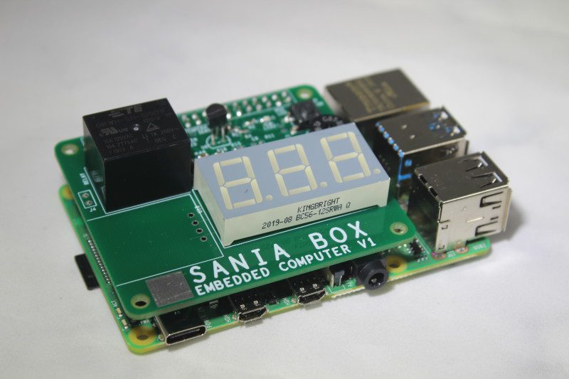
Sania Box encourages kids to build a PC – no adult required
Reading Time: 2 minutesSania Jain is one of a growing band of teenage entrepreneurs keen to share their ideas with peers. In her case, her idea is to spread a love of coding and STEAM skills with children who may not have had a chance to explore it before. Sania’s eponymously-named DIY computer box is powered…
-

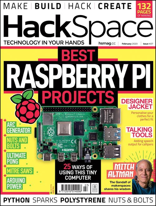
HackSpace’s 25 ways to use a Raspberry Pi
Reading Time: 2 minutesThe latest issue of HackSpace magazine is out today, and it features a rather recognisable piece of tech on the front cover. 25 ways of using this tiny computer From personal computing and electronic fashion to robotics and automatic fabrication, Raspberry Pi is a rather adaptable piece of kit. And whether you…
-

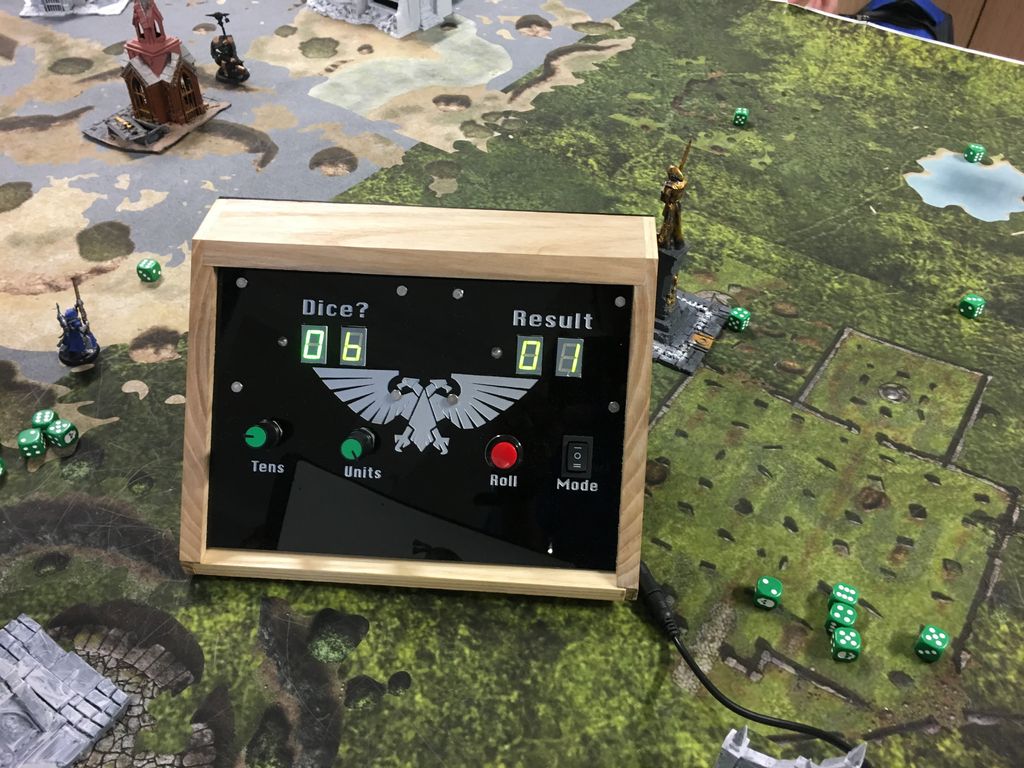
An Arduino-powered dice generator
Reading Time: 2 minutesAn Arduino-powered dice generator Arduino Team — January 22nd, 2020 Board games can be fun, but what happens when you need more than six, 12, or even 20 possibilities to decide your character’s fate? One could of course use several dice, or an online simulator, but creator “Rehaan33” built something much more…
-

Arduino Education launches four new STEAM products at Bett 2020
Reading Time: 4 minutesDuring Bett Show 2020, Arduino will launch the Arduino Education learning evolution: four new STEAM products for students in lower secondary school through to university. Arduino Education will also announce a partnership with the Fraunhofer Initiative: “Roberta – Learning with Robots” in Germany. Arduino Education‘s latest products — CTC GO! Motions Expansion…
-

Citizen science traffic monitoring with Raspberry Pi
Reading Time: 2 minutesHomes in Madrid, Dublin, Cardiff, Ljubljana, and Leuven are participating in the Citizens Observing UrbaN Transport (WeCount) project, a European Commission–funded research project investigating sustainable economic growth. 1,500 Raspberry Pi traffic sensors will be distributed to homes in the five cities to gather data on traffic conditions. Every hour, the devices will…
-

Add navigation to a low-cost robot
Reading Time: 7 minutesIf you completed the steps in the last low cost robot-building article, you’ll have added a camera to your Raspberry Pi-powered lunchbox robot. This enabled your robot to take photos and provided a robot’s-eye view of the world. Now a robot builder gets to take this much further and make the robot…
-

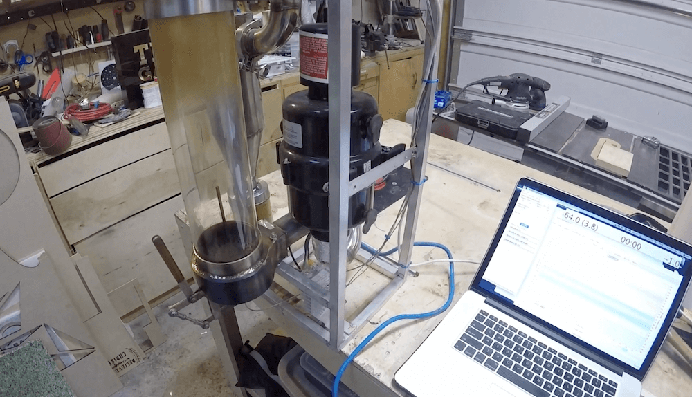
Roast your own coffee beans with the help of Arduino
Reading Time: < 1 minuteRoast your own coffee beans with the help of Arduino Arduino Team — January 21st, 2020 Apparently not content with simply brewing his coffee to perfection, Alex Campbell can actually take control of the roast itself thanks to his beautiful fluid bed roasting rig. His DIY device is constructed using a…
-

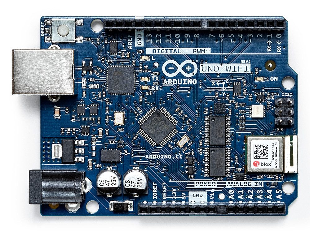
Open source power for classrooms: Arduino Uno WiFi Rev2 for CTC GO! joins Open Roberta
Reading Time: 2 minutesOpen source power for classrooms: Arduino Uno WiFi Rev2 for CTC GO! joins Open Roberta Arduino Team — January 21st, 2020 [youtube https://www.youtube.com/watch?v=M_ya3daY3GE?feature=oembed&w=500&h=281] Dream team for classrooms worldwide: Arduino Uno WiFi Rev2 for CTC GO! joins Open Roberta Lab, the biggest open source coding platform made in Europe. The Arduino Uno WiFi…
-

TechWiser’s giant Raspberry Pi AirPod speaker (and more)
Reading Time: 2 minutesYouTube is a haven for awesome Raspberry Pi projects, and we often spend time scanning through the platform’s wares for hidden gems. One such hidden gem is this video from TechWiser, in which they showcase some of their favourite Raspberry Pi projects: Cool Raspberry Pi 4 Projects We Use At TechWiser Here…
-

Bit Time Rotary Dial Phone project showcase
Reading Time: 4 minutesThe Rotary Dial Phone project is part of a wider initiative called Bit Time – a project that has been running in Basildon, Essex over recent months. It’s the brainchild of Dave Norton and Laura Travail. Dave is a digital Artist and drama practitioner whose work ranges from large-scale interactive installations to…
-

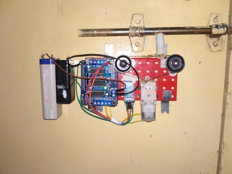
Automate your door latch with a simple app-controlled system
Reading Time: < 1 minuteAutomate your door latch with a simple app-controlled system Arduino Team — January 20th, 2020 Adnan.R.Khan recently decided to give his room’s sliding door latch an upgrade by designing a mechanism to open and close it, using little more than an Arduino Uno and Bluetooth module. His automated device is operated…
-

Arduino Education nominated for Bett Award
Reading Time: 2 minutesArduino Education nominated for Bett Award Arduino Team — January 20th, 2020 The Arduino Engineering Kit has been nominated as a BETT Awards 2020 finalist in the “Higher Education or Further Education Digital Services” category. About the Bett Awards The Bett Awards are a celebration of the inspiring creativity and innovation that…
-

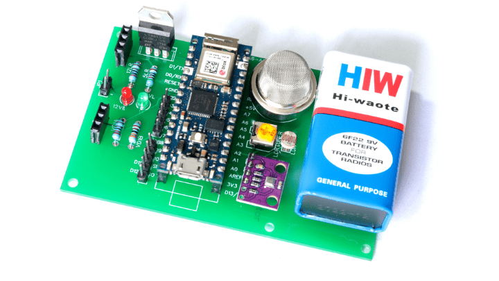
Monitor your home with this Nano 33 IoT-based system
Reading Time: < 1 minuteMonitor your home with this Nano 33 IoT-based system Arduino Team — January 20th, 2020 Using an Arduino Nano 33 IoT, Jithin Sanal designed a home monitoring system capable of detecting noxious gases with an MQ2 sensor as well as sensing temperature, pressure, humidity, and ambient light via a BME280 sensor…
-

An educator’s summer dream – to add more robotics into their classroom
Reading Time: 3 minutesHow Arduino Education helped educator James Jones boost students’ 21st century skills and robotics knowledge across 23 middle schools in Orlando, Florida. More and more teachers face the difficulty of instilling the right skills and knowledge, as well as a flexible mindset, that better prepare their students for future career opportunities. “Today,…
-
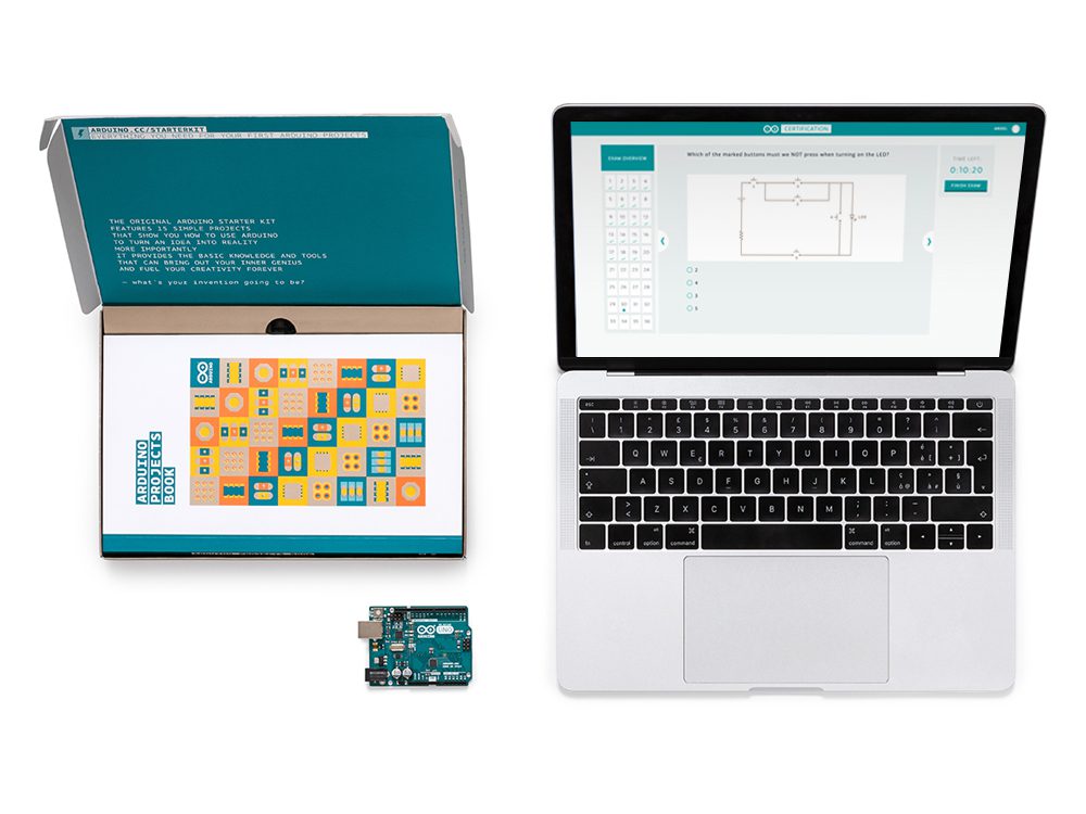
The Arduino Fundamentals Certification Exam is now available in Spanish and Italian!
Reading Time: 3 minutesFor enthusiasts, the Fundamentals Exam is the first tier in the Arduino Certification Program (ACP), designed to test entrants knowledge in Arduino-related electronics, programming, and physical computing. The exam is available for everyone interested in officially certifying their skills and knowledge on Arduino, that could, for example, be referred to in a…
-

Connect your Raspberry Pi 4 to an iPad Pro
Reading Time: 2 minutesHave you ever considered attaching your Raspberry Pi 4 to an Apple iPad Pro? How would you do it, and why would you want to? Here’s YouTuber Tech Craft to explain why Raspberry Pi 4 is their favourite iPad Pro accessory, and why you may want to consider using yours in the…
-

Designing an extremely realistic animatronic heart with Arduino
Reading Time: 2 minutesDesigning an extremely realistic animatronic heart with Arduino Arduino Team — January 17th, 2020 In his latest video, Will Cogley has created an animatronic heart so realistic that you might wonder if it’s the actual thing. The device is made out of molded silicon with fake blood poured on top to enhance…