Kategorie: Linux
-

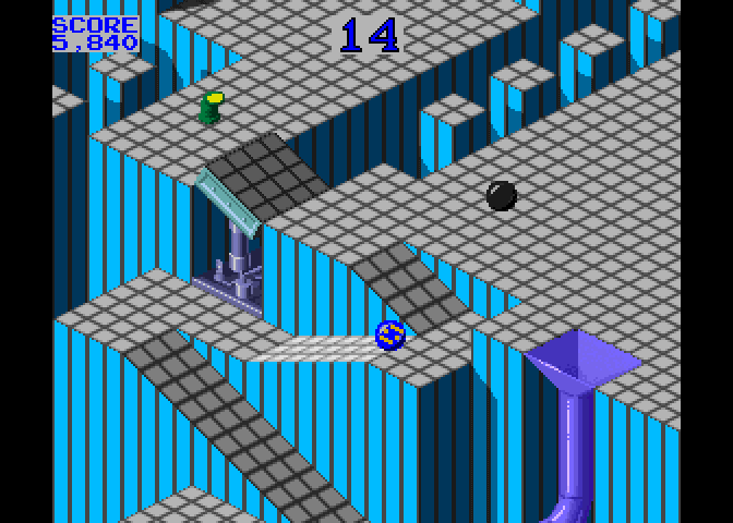
Code a homage to Marble Madness | Wireframe #34
Reading Time: 4 minutesCode the map and movement basics of the innovative marble-rolling arcade game. Mark Vanstone shows you how. Each of Marble Madness’ six levels got progressively harder to navigate and had to be completed within a time limit. Marble Madness Hitting arcades in 1984, Atari’s Marble Madness presented a rather different control mechanism…
-

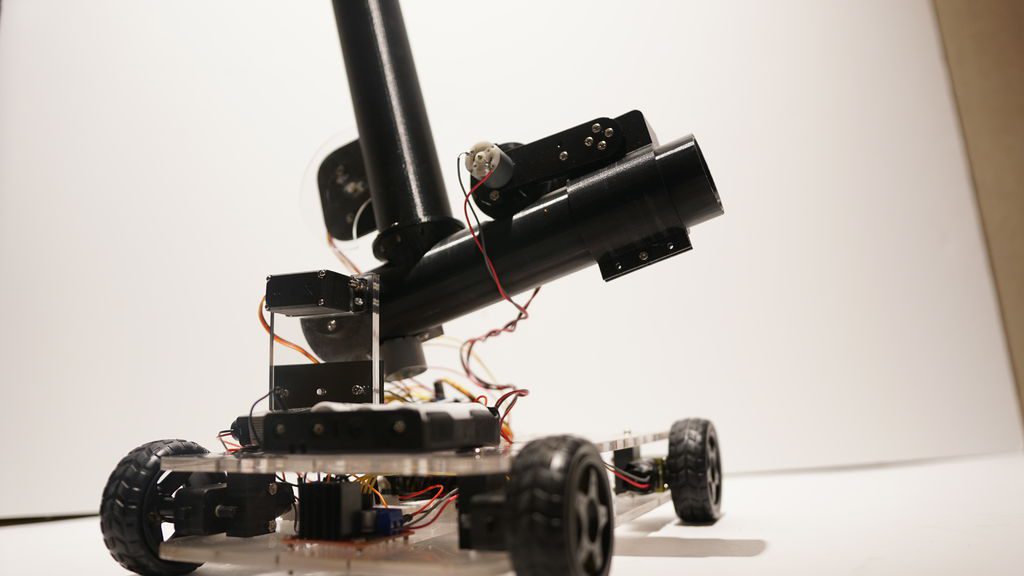
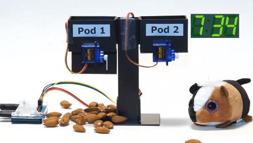
Pingo, the motion-detecting ping pong ball launcher
Reading Time: < 1 minutePingo, the motion-detecting ping pong ball launcher Arduino Team — March 11th, 2020 If you want to “enhance your athletic training regimen,” or perhaps just have a bit of fun with robotically launched ping pong balls, then be sure to check out the Pingo apparatus shown in the video below. This…
-

Our approach to developing progression for teaching computing
Reading Time: 4 minutesPart of our work in the consortium behind the National Centre for Computing Education (NCCE) is to produce free classroom resources for teachers to deliver the Computing curriculum to students aged 5–16 in England. Our Director of Educator Support Carrie Anne Philbin describes how we define and represent progression in these resources.…
-

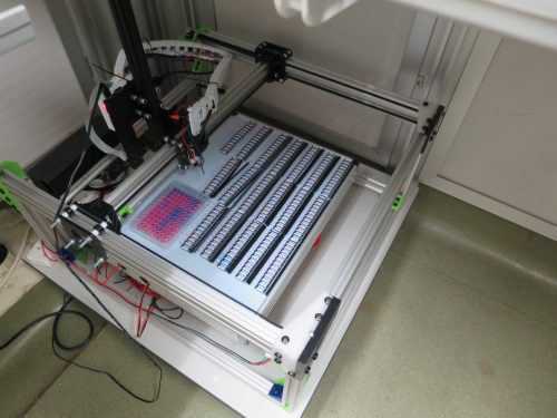
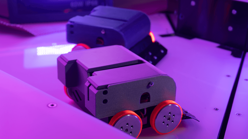
Raspberry Pi vs antibiotic resistance: microbiology imaging with open source hardware
Reading Time: 4 minutesThe Edwards Lab at the University of Reading has developed a flexible, low-cost, open source lab robot for capturing images of microbiology samples with a Raspberry Pi camera module. It’s called POLIR, for Raspberry Pi camera Open-source Laboratory Imaging Robot. Here’s a timelapse video of them assembling it. Measuring antibiotic resistance with…
-

This pair of Arduino glasses stops you from touching your face
Reading Time: < 1 minuteThis pair of Arduino glasses stops you from touching your face Arduino Team — March 10th, 2020 Touching your face is a subconscious behavior that we all do, and it is also an easy way to pick up illnesses like the coronavirus and flu. However, like many infectious diseases, proper hygiene…
-

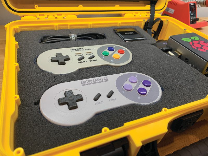
AdventurePi: portable Raspberry Pi arcade machine
Reading Time: 3 minutesWhen pondering his next project with a Raspberry Pi, he decided to create AdventurePi, a portable gaming device that would be as robust as an arcade machine. “A lot of people my age move around a lot or live in apartments and no one really wants to lug around a free-standing cabinet,…
-

The Watchman is a 3D-printed robot head that follows your face with realistic eyeballs
Reading Time: 2 minutesThe Watchman is a 3D-printed robot head that follows your face with realistic eyeballs Arduino Team — March 9th, 2020 When you step out in public, you’ll often be filmed by a number of cameras and perhaps even be analyzed by tracking software of some kind. The Watchman robot head by Graham…
-

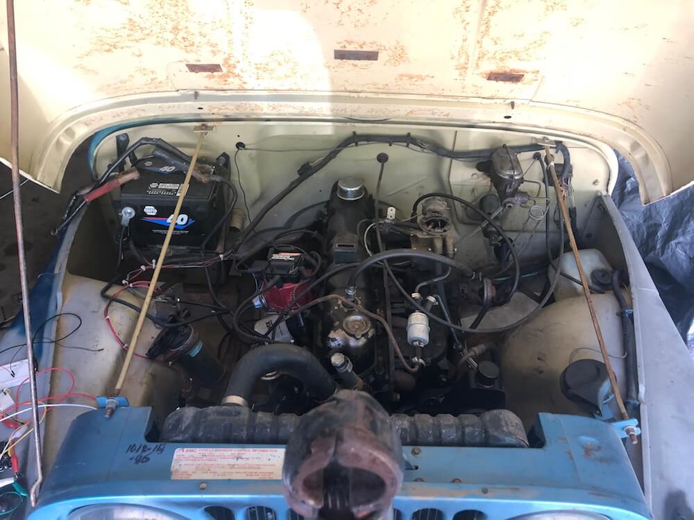
Start a 1976 Jeep with voice commands using a MacBook and an Arduino
Reading Time: < 1 minuteStart a 1976 Jeep with voice commands using a MacBook and an Arduino Arduino Team — March 9th, 2020 After being given a 2009 MacBook, John Forsyth decided to use it to start a 1976 Jeep via voice control. The build uses the laptop’s Enhanced Dictation functionality to convert text into…
-

How to use a button with a Raspberry Pi
Reading Time: < 1 minuteHere’s our latest How to use video, showing you how to connect a button to your Raspberry Pi. HOW TO USE a BUTTON with Raspberry Pi Learn how to use a tactile button with your Raspberry Pi. They’re a great addition to any digital making project! Subscribe to our YouTube channel:…
-

Make a hamster feeder with Raspberry Pi Zero
Reading Time: < 1 minutePeople make marvellous things for their pets with Raspberry Pi. Here’s a splendid hamster feeder tutorial from Christopher Barnatt of Explaining Computers, just perfect if you’re after a small project for this weekend. Raspberry Pi Zero Hamster Feeder Raspberry Pi servo-controlled pet feeder, using a Raspberry Pi Zero and two SG90…
-

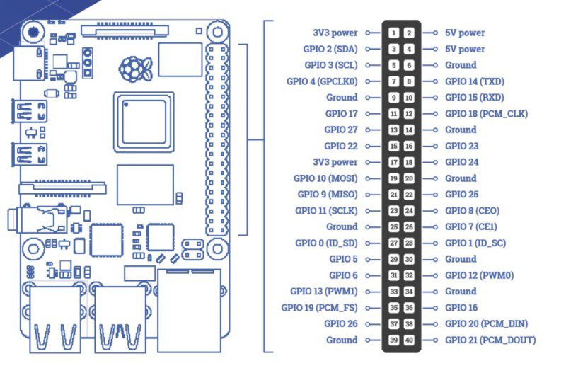
Get started with electronics and Raspberry Pi
Reading Time: 8 minutesRaspberry Pi is the gateway to electronics and computing Raspberry Pi has made a huge impact, not only on computer science education but also in the realm of makers and inventors. As well as being a really good-value computer, it gives the owner endless possibilities of connecting other electronics to it to…
-

Creating an online robot fighting game using Arduino MKR1000 WiFi
Reading Time: 7 minutesThis is a guest post from Surrogate, a team of developers building games that people play in real-life over the internet. We introduced this concept last year, and have launched three games so far. Our final game of 2019 was SumoBots Battle Royale — where players from anywhere in the world can…
-

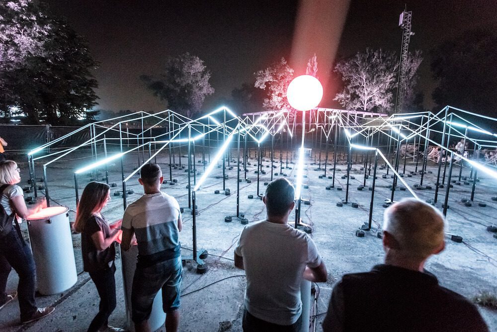
The Lightwaves is a participatory audio-visual installation
Reading Time: 2 minutesThe Lightwaves is a participatory audio-visual installation Arduino Team — March 5th, 2020 Music and synchronized lighting can be a beautiful combination, evident by panGenerator’s recent installation that was commissioned by the M?skie Granie concert tour in Poland. The interactive sculpture was comprised of 15 drums that trigger waves of light traveling…
-

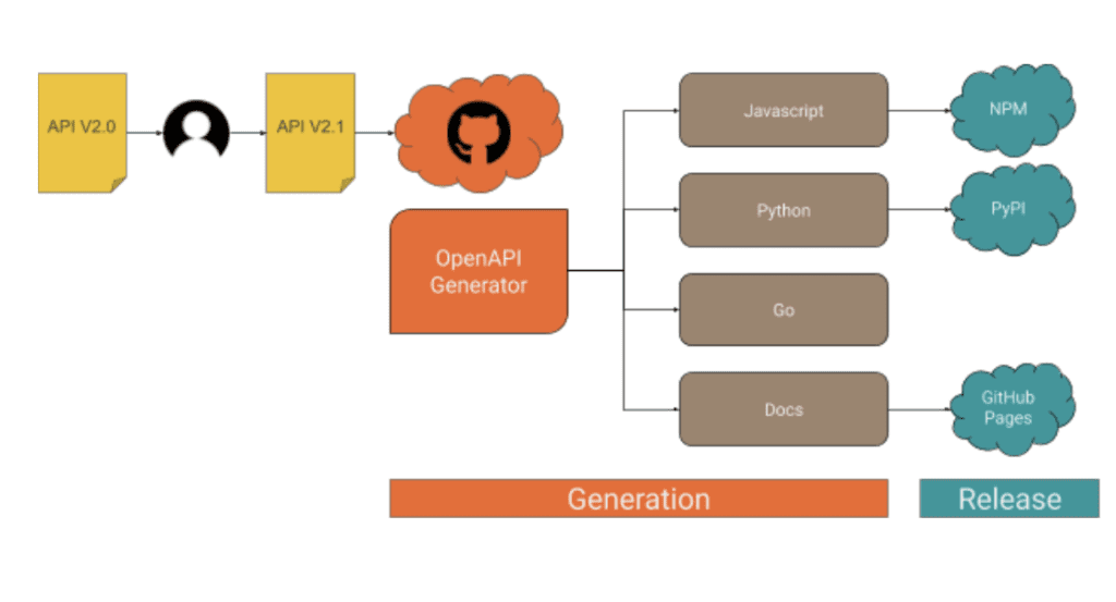
How to deal with API clients, the lazy way — from code generation to release management
Reading Time: 5 minutesThis post is from Massimiliano Pippi, Senior Software Engineer at Arduino. The Arduino IoT Cloud platform aims to make it very simple for anyone to develop and manage IoT applications and its REST API plays a key role in this search for simplicity. The IoT Cloud API at its core consists of…
-

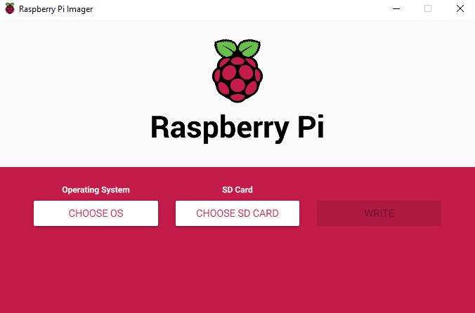
Introducing Raspberry Pi Imager, our new imaging utility
Reading Time: 3 minutesWe’ve made a simpler way to image your microSD card with Raspbian, the official Raspberry Pi operating system, and other operating systems. Introducing our new imaging utility, Raspberry Pi Imager. Simplifying the Raspberry Pi experience For me, one of the most important aspects of the Raspberry Pi experience is trying to make…
-
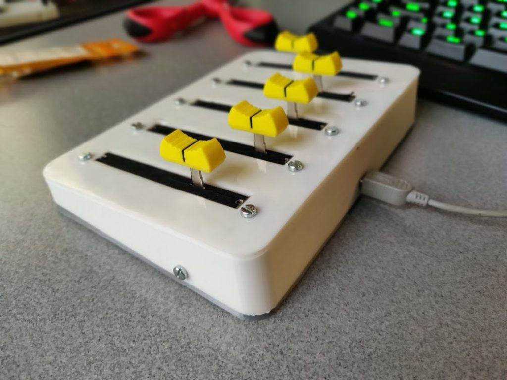
Control the volume of programs running on your Windows PC like a DJ
Reading Time: < 1 minuteControl the volume of programs running on your Windows PC like a DJ Arduino Team — March 4th, 2020 If you have multiple applications open in Windows, you may want one to be louder than the other, but what if you want to adjust levels with physical sliders like an actual…
-

NeoPixel LED Mirror
Reading Time: 3 minutes“The project uses a Raspberry Pi 3B+, a Raspberry Pi Camera [Module], Python, 3D printing, and 576 NeoPixel LEDs to create an interactive art piece that shows you your reflection in ‘low resolution’ by lighting up a grid of LEDs,” says Alex. In essence, it’s taking your picture using a Raspberry Pi Camera…
-

SD Card Speed Test
Reading Time: 6 minutesSince we first launched Raspberry Pi, an SD card (or microSD card) has always been a vital component. Without an SD card to store the operating system, Raspberry Pi is pretty useless*! Over the ensuing eight years, SD cards have become the default removable storage technology, used in cameras, smartphones, games consoles…
-

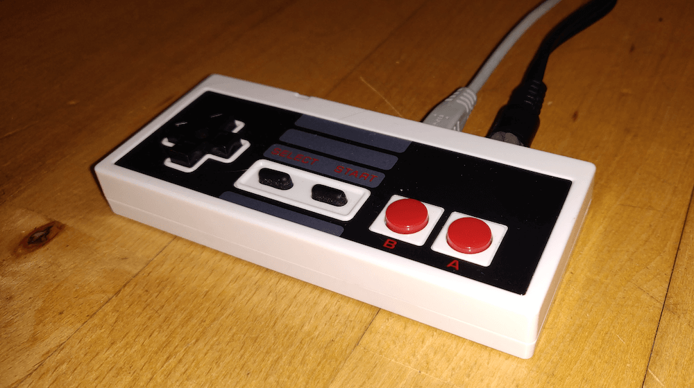
An Arduino Tetris console inside of an NES controller
Reading Time: 2 minutesAn Arduino Tetris console inside of an NES controller Arduino Team — March 3rd, 2020 Tetris was as a perfect complement to Nintendo’s original Game Boy when it came out in 1989, and now “Copper Dragon” has been able to fit an entire system for it — sans monitor or speakers — inside…
-

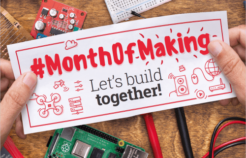
The MagPi 91: #MonthOfMaking is back for 2020!
Reading Time: 4 minutesIf you read The MagPi, it’s safe to say you like making in some way. The hobby has exploded in popularity over the last few years, thanks in no small part to a burgeoning online community and the introduction of low-cost computing with Raspberry Pi. Last year we decided to celebrate making…
-

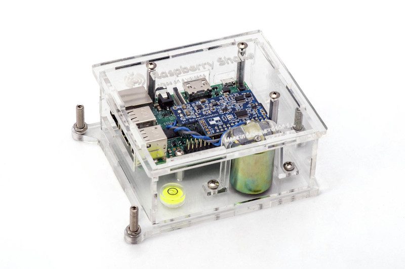
Build a seismograph with Raspberry Shake
Reading Time: 6 minutesRaspberry Shake is a great project for budding geologists and citizen scientists because it’s relatively simple to assemble (although you do need to be careful to handle and level the parts correctly). Once built, it’s low maintenance, sitting in a quiet part of your home or office, waiting for the earth to move.…