Kategorie: Linux
-

Win one of ten Argon ONE cases!
Reading Time: < 1 minuteSave 37% off the cover price with a subscription to The MagPi magazine. Try three issues for just £5, then pay £25 every six issues. You’ll save money and get a regular supply of in-depth reviews, features, guides and other PC enthusiast goodness delivered directly to your door every month. Subscribe
-

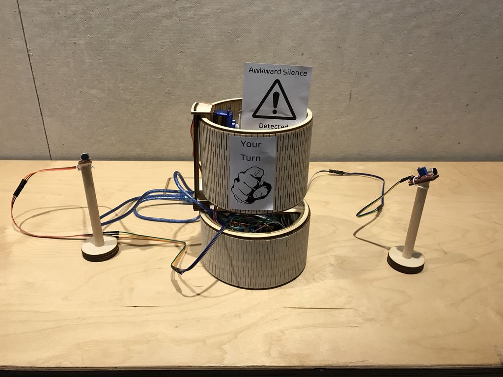
SASSIE helps prevent awkward gaps in conversation
Reading Time: < 1 minuteSASSIE helps prevent awkward gaps in conversation Arduino Team — March 24th, 2020 Whether it’s with an old friend or new acquaintance, we’ve all had those awkward gaps in conversation. Do you speak next, or let the other person lead the discussion? If that’s not happening naturally, then SASSIE, or “System…
-

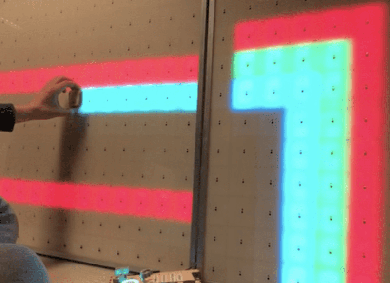
1,156 LEDs make up these dual acrylic light-up panels
Reading Time: 2 minutes1,156 LEDs make up these dual acrylic light-up panels Arduino Team — March 24th, 2020 What does one do with over 1,000 LEDs, white acrylic, and 288 IR sensors? If you’re Redditor “jordy_essen,” you create an interactive light panel. In one mode, the user pull a reflective tool across the sensors to…
-

Stay busy in your Vault with a Raspberry Pi Zero Pipboy
Reading Time: 2 minutesWhile being holed up in the Vaults living off our stash of Nuke cola, we’ve come across this mammoth junk-build project, which uses Raspberry Pi Zero W to power a working Pipboy. Pipboy scrap build No Description UK-based JustBuilding went full Robert House and, over several months, built the device’s body by…
-

Arduino’s response to the Covid-19 outbreak
Reading Time: < 1 minuteArduino’s response to the Covid-19 outbreak Arduino Team — March 23rd, 2020 For the latest update regarding Arduino’s response to the Covid-19 outbreak please click here. Priority Service for the Design & Production of Essential Medical and Personal Protective Equipment (PPE) As companies around the globe rapidly react to governments’ calls…
-

Don’t forget about Steam Link on Raspberry Pi
Reading Time: 2 minutesConnect your gaming PC to your TV with ease, thanks to Steam Link and Raspberry Pi. A Steam Link to the past Back in 2018, we asked Simon, our Asset Management Assistant Keeper of the Swag, Organiser of the Stuff, Lord Commander of the Things to give Steam Link on Raspberry Pi…
-

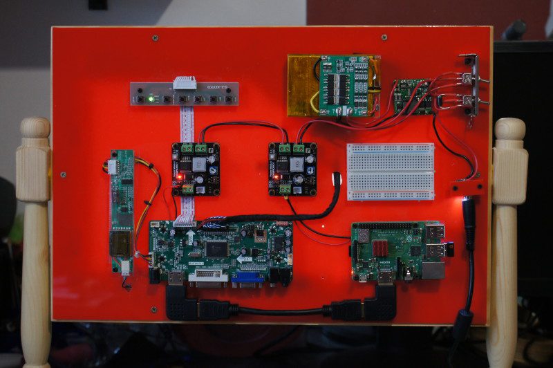
Raspberry Pine
Reading Time: 2 minutesWood-n’t it be nice The screen is mounted in a custom pine frame and stand. The frame is built using strips of small pine architrave backed by pine strips, offset to give a suitable rebate for the panel to fit and hiding the border. The side supports are modified pine staircase spindles.…
-

Tune in to the official Arduino Day 2020 livestream
Reading Time: < 1 minuteTune in to the official Arduino Day 2020 livestream Arduino Team — March 20th, 2020 We’re just hours away from (virtually) celebrating Arduino Day! Join us on Saturday for our official livestream, starting at 2pm CET. We’ll connect with community events from all around the world as well as hear from Arduino…
-

Work remotely with Arduino Create — get a free upgrade now
Reading Time: 2 minutesWork remotely with Arduino Create — get a free upgrade now Arduino Team — March 20th, 2020 To help individuals work remotely and share their designs with team members, we’re providing a free three-month upgrade to the Arduino Create Maker plan to all 1.4 million users of Create as well as new subscribers…
-

Activities you can do at home this week!
Reading Time: 3 minutesAt the Raspberry Pi Foundation, our mission is to put the power of computing and digital making into the hands of people all over the world. We know that a lot of families around the globe are navigating school closures and practicing social distancing right now to keep their communities healthy and…
-

VersaTouch brings touch localization and force sensing to everyday surfaces
Reading Time: 2 minutesVersaTouch brings touch localization and force sensing to everyday surfaces Arduino Team — March 19th, 2020 Researchers from the University of Auckland in New Zealand’s are exploring a new way to construct interactive touch surfaces using finger-mounted audio transducers. VersaTouch — which works on everyday surfaces — uses one or more receivers…
-

Build a physical game controller for Infinite Bunner
Reading Time: 5 minutesIn HackSpace magazine issue 28 we had a look at how to create an ultrasonic controller for a version of Pong called Boing!. This month, we’re going to take a step further forward through video game history and look at the game Frogger. In this classic game, you control a frog as…
-

Learn SQL and database design with Raspberry Pi
Reading Time: 3 minutesSQLite SQLite’s site is basic, but sqlitetutorial.net provides free interactive training. As well as covering SQL for SQLite (all platforms have slightly different implementations of SQL), there is a Python-specific course. Here, you can learn how to use PySQLite, the Python bindings for SQLite. Not only is the SQL language covered, but how to…
-

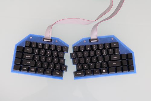
Building a split mechanical keyboard with a Raspberry Pi Zero controller
Reading Time: 3 minutesLooking to build their own ergonomic mechanical split keyboard, Gosse Adema turned to the Raspberry Pi Zero W for help. So long, dear friend Gosse has been happily using a Microsoft Natural Elite keyboard for years. You know the sort, they look like this: Twenty years down the line, the keyboard has…
-

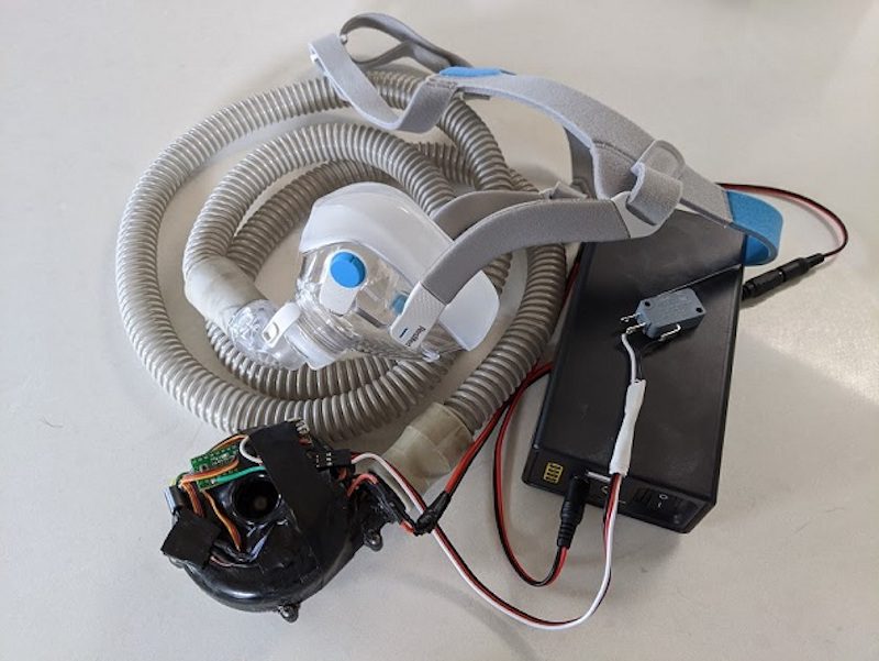
Designing a low-cost, open source ventilator with Arduino
Reading Time: < 1 minuteDesigning a low-cost, open source ventilator with Arduino Arduino Team — March 17th, 2020 Desperate times call for desperate measures, and while making your own medical equipment isn’t normally advisable, Johnny Lee’e project explores how to turn a CPAP machine into a ventilator. The idea is that since these machines are…
-

Wireframe’s deep(ish) dive into the glorious double jump
Reading Time: 2 minutesYoshi aside, we can’t think of anyone who isn’t a fan of the double jump. In their latest video, the Wireframe magazine team take a deep(ish) dive into one of video gaming’s most iconic moves. What is the Double Jump | Wireframe Deep Dive The humble jump got a kick in 1984…
-

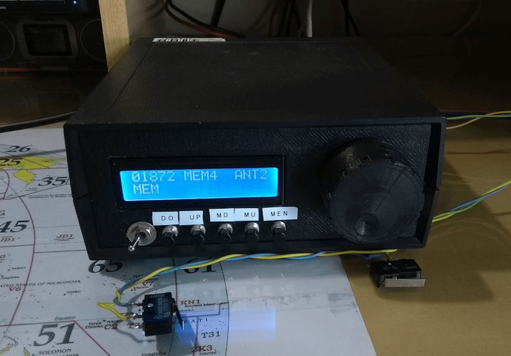
Using an Arduino/CNC shield setup for ham radio control
Reading Time: < 1 minuteUsing an Arduino/CNC shield setup for ham radio control Arduino Team — March 16th, 2020 Loop antennas for ham radios use heavy duty variable capacitors for tuning. Since such capacitors need to be physically turned for adjustment, radio enthusiast Jose B.O. made his own remote rig using an Arduino Uno and…
-
Thales, Telstra, Microsoft and Arduino deliver scalable trust for easy-to-deploy IoT Applications
Reading Time: 2 minutesWe’ve partnered with Thales, Telstra and Microsoft to pave the way for scalable security for connected IoT devices, by implementing a solution that enables trusted and secure end-to-end communication between device and cloud. The solution enables instant and standardized mutual authentication between a device and a cloud platform via cellular networks, while…
-
NexDock 2 review
Reading Time: 2 minutesAnd what a lovely screen it is: the 13.3-inch IPS 1920×1080 display is a delight to look at, even if the chunky borders are a bit retro. The edge-to-edge full-sized backlit keyboard is equally impressive, with responsive chiclet-style keys that are suitably clicky. Typing is a breeze. The whole thing is set…
-

Recreate Flappy Bird’s flight mechanic | Wireframe #29
Reading Time: 3 minutesFrom last year’s issue 29 of Wireframe magazine: learn how to create your own version of the simple yet addictive side-scroller Flappy Bird. Raspberry Pi’s Rik Cross shows you how. Flappy Bird: ridiculously big in 2014, at least for a while. Flappy Bird was released by programmer Dong Nguyen in 2013, and…
-

How the Raspberry Pi Foundation is responding to the novel coronavirus
Reading Time: 4 minutesIn this blog post, I want to share an update on how the Raspberry Pi Foundation is responding to the novel coronavirus and what it means for our work to support people all over the planet to change their world through technology. The situation is changing rapidly, and we’ll update this blog…
-
Arduino CLI: An introduction
Reading Time: 3 minutesIt’s been a long time since we first launched our Arduino IDE inspired by the glorious Processing interface, and what started as a Java UI wrapper for build scripts has gone through countless iterations over the past fifteen years. Some may remember the transition between 1.0 and 1.5, or the application’s icon…