Kategorie: Reviews

  • Retro education

    Retro education

    Reading Time: 2 minutes

    When I wasn’t reading books or playing adventure games, I was learning BASIC and making my own creations. Computing classes covered everything from acid-etched circuits to PASCAL programming.

    As I worked my way through school, the computer became less about exploring the potential of a wonderful new gizmo and more about fitting students into the mould of office life. By the time I went to college, I was being taught touch-typing and how to format word-processing documents.

    My love of narrative was filled with English and art, and computing became a personal hobby and less of an academic study. This is a shame because computers are incredible things. Packed with unlocked potential that can be used in all kinds of scientific and creative endeavours. Without computers, we wouldn’t have modern art in its current form; or video, film, or modern music. Still, I managed to bring it all together by editing a magazine about computers and taking courses at MITx.

    It’s no surprise to me that some of the most creative people I’ve ever met are quite nerdy; and vice versa. The secretarial training was the opposite of both: learning by rote with no understanding. It was bland. In retrospect, I should have taken the electronic typewriter apart to see what was going on inside.

    I like to think that Raspberry Pi and the new Pico microcontrollers can fill the tech void that is teaching, otherwise smart kids, basic office skills to tick government check boxes. Simply putting bare tech in front of kids who are interested can make all the difference.

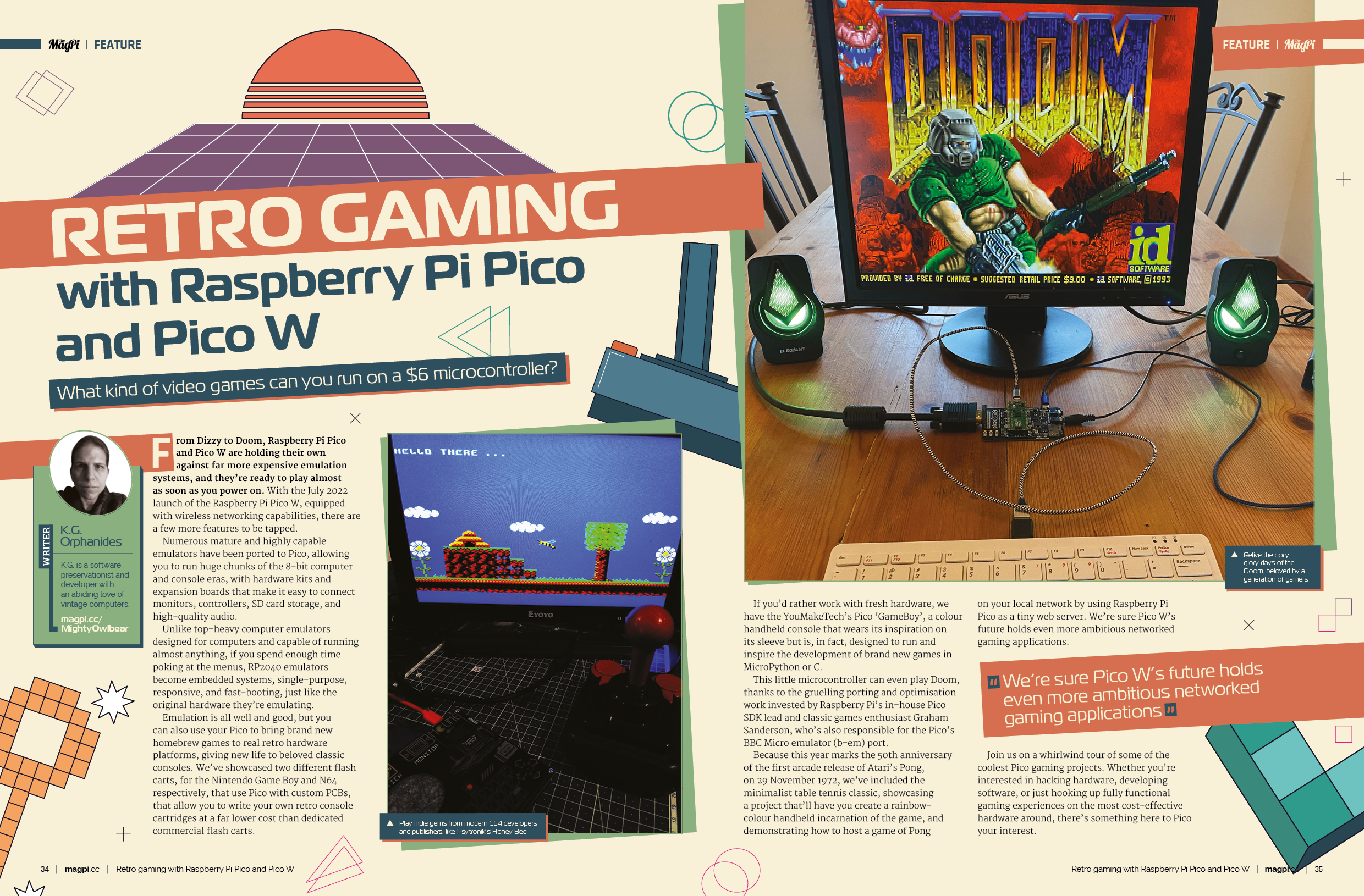
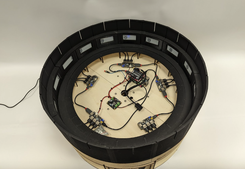
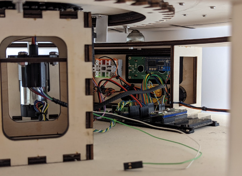
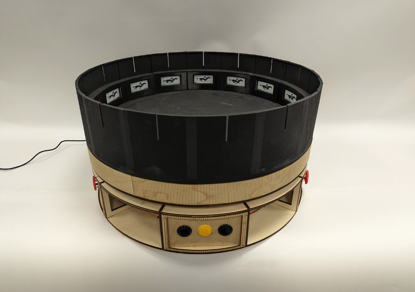
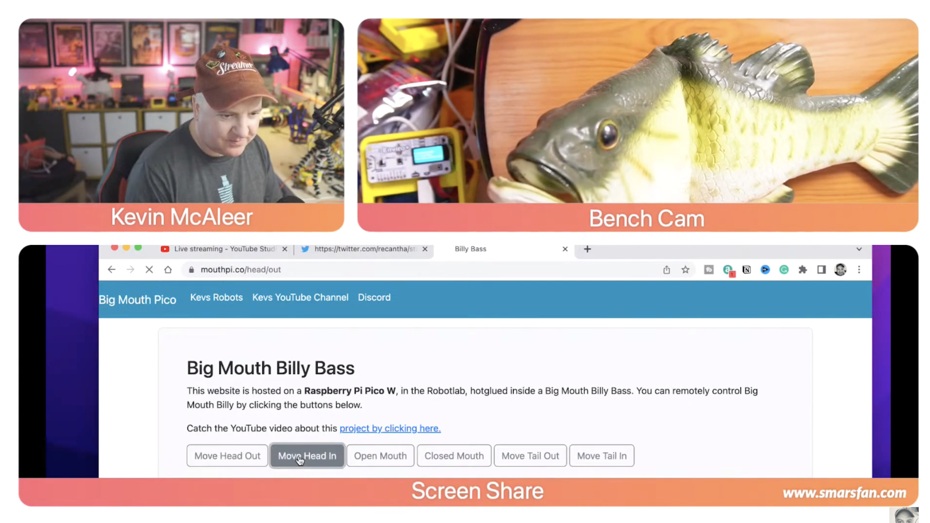
    Our retro gaming with Pico feature obviously appeals to retro geeks like me who remember the 8-bit days with love and affection. I learnt coding and computing by experimentation. Retro computing on a modern device, like Pico, also shows how cutting-edge technology can trace a path back to earlier days and help us gain an understanding of computing development.

  • LEGO Submarine 4.0

    LEGO Submarine 4.0

    Reading Time: 4 minutes

    This is the fourth LEGO submarine design he has completed. The first three variously used propellers to add or reduce buoyancy (“gravity and buoyancy stay always the same while the propellers exert force”); a balloon, and an air compressor to adjust the amount of water displaced, thereby controlling whether the submarine sinks or rises; and a piston ballast to suck in more water to add weight and increase the sub’s gravity.

    He settled on the last method for Submarine 4.0, despite the difficulty of gauging the neutral buoyancy point. However, it had proved a more stable setup and would not compress under pressure when submerged. Most importantly, “you can measure the piston position with a LEGO EV3 motor that contains a tachometer. That will help the control loop.” This loop is also the reason for using Raspberry Pi: as we reported last issue, he had recently made an impressive inverted pendulum that uses a PID (proportional integral derivative) control loop running on Raspberry Pi Zero 2 W to accurately measure and compensate for constantly changing speed, location, and pressure levels.

    He planned a similar setup here, to monitor and control the submarine’s depth. He soon found the wireless LAN connectivity invaluable when tweaking the PID parameters and updating any Python code without having to physically connect to the Pi Zero 2 W via USB (which would have involved carefully extracting everything from the precision environment he’d created). He now says wireless LAN is “an absolute necessity” which “made the development process a lot faster.”

    Underwater flying machine

    A fair amount of time and effort went into creating the submarine’s beautiful transparent acrylic case with tightly fitting and invisible end caps. The basic acrylic cylinders were precision-cut and end pieces with rubber seals attached to form a waterproof unit. LEGO gears were fitted to control the syringe that would adjust the buoyancy.

    An absolute pressure sensor (which measures pressure relative to a vacuum, and is unaffected by the ambient pressure) is used to track the submarine’s depth. It connects to Raspberry Pi Zero 2 W via I2C. A SparkFun TFMini-S Micro laser sensor provides a second means of measuring the submarine’s depth, but its accuracy is affected by the murky environments in which he was using it.

    A more successful purchase was the radio board he harvested from a cheap Chinese toy submarine, having chosen it for its 27MHz radio frequency (needed to penetrate water) and its aesthetically pleasing controller. Raspberry Pi provides enough juice to power the board, so he decided to discard its LiPo battery in favour of a LEGO waterproof rechargeable battery pack.

    Diving for pearls

    In Submarines 2.0 and 3.0, he used lead pellets to provide extra weight, but they were quite sizable and took up valuable space inside the submarine’s frame. For this version, he splashed out on expensive 2.5 mm tungsten pellets weighing 18 g/cm3. Weighed on a kitchen scale, the submarine was 826 g, with a displacement of 1614 g. He added 580 g of tungsten pellets to make the submarine dive gently, making adjustments using the syringe.

    To prevent entanglements while on manoeuvres, he attached a magnet on the inside top of the submarine frame so he could ‘fish’ the craft out of danger, if needs be. With lots of weeds and obstructions on the river bed, he was keen to avoid collisions, especially as it cost more than 600 EUR.

    Thankfully, Submarine 4.0 has performed well in a range of environments from swimming pools and water tanks to a nearby river. “It drives well under water. The automatic depth control really makes controlling it easy, as you can focus on pressing only forward/backward and left/right buttons and forget the dive/surface buttons. I’d say the controls are as good as in Submarine 2.0, which has been the best so far,” he reports.

    Nonetheless, as a perfectionist, he notes several areas for improvement.

  • Pico W retro gaming special in The MagPi magazine issue #122

    Pico W retro gaming special in The MagPi magazine issue #122

    Reading Time: 2 minutes

    Retro Gaming with Raspberry Pi Pico and Pico W

    Retro Gaming with Raspberry Pi Pico & Pico W 

    Our resident retro games expert KG Orphanides has crafted a superb feature for this month’s edition of The MagPi magazine. Discover how to emulate classic computers, hack 1980s hardware, and play retro games on a $6 microcontroller.

    Build a Mini Magic Mirror

    Build a Mini Magic Mirror

    A magic mirror is one of the timeless Raspberry Pi projects that we’ve given a new spin this month. Using a smaller screen and Raspberry Pi Zero W we’ve created a range of magic mirror projects that you can deploy around the home.

    LEGO Submarine 4.0

    LEGO Submarine 4.0 

    Get underwater with this incredible build. Using LEGO, a syringe, a pressure sensor and a wireless communication board this build can head into (and underneath) the water.

    Raspberry Pi Radio: Add a DJ and jingles

    Add a DJ & Jingles to your Raspberry Pi Radio

    Sean McManus has built an incredible Raspberry Pi Radio that doesn’t just play songs, it uses Raspberry Pi smarts to create a virtual DJ. The disc jockey uses voice technology to interject and announce tracks, and even plays jingles and stings.

    Build a Poltergust G-00

    Build your own Poltergust G-00

    The MagPi’s very own Rob Zwetsloot has created this incredible 3D-printed ghostbusting vacuum from Luigi’s Mansion 3. This month Rob walks us through the build process.

    The Centre for Computing History interview

    The Centre for Computing History interview

    We talk to the incredible museum located in Cambridge about its wonderful range of classic computers, retro games, and a giant processor that plays Tetris.

  • Win! 1 of 5 EPD Pico Kits

    Win! 1 of 5 EPD Pico Kits

    Reading Time: < 1 minute

    Subscribe

  • LEGO Reaction Wheel Inverted Pendulum

    LEGO Reaction Wheel Inverted Pendulum

    Reading Time: 3 minutes

    Well, that’s the theory, but in practice it’s not quite so easy and, as shown in his YouTube video, Juha had to alter his Python code repeatedly and make hardware adjustments to get the system to work to his satisfaction.

    Precision control

    A gyroscope and accelerometer on a mini IMU (inertia measurement unit) board are used to measure the pendulum angle, while Raspberry Pi runs a control loop for filtering data and calculating PID (proportional–integral–derivative) controller outputs for adjusting the motor’s speed and direction. Automatically calculating corrections based on feedback, PID is one of the most common control methods used in industrial and mechanical applications, such as in a car’s cruise control system. It’s also fairly easy to implement.

    “Others have used LQR [linear–quadratic regulator] control for inverted pendulums,” notes Juha, “but it looks too mathematical and difficult for me. As for tuning the PID parameters, I didn’t have any approach other than ‘try and see.’ It got good laughs in the YouTube comment section as it looks so unprofessional.”

    While Juha opted to use a Raspberry Pi Zero 2 W for its fast bootup speed, “CPU load was only 5% running the control loop with a 1 ms interval, so it would work with a much less capable board.” He even tried using a Pico, which “worked OK in terms of processing power, but then I realised I need to store tens of megabytes of log data for drawing nice graphs for the video.”

    Amazingly, before this project, Juha had never used a Raspberry Pi before and had minimal experience with electronics. “I had to figure out how GPIO works, what are pull-down and pull-up resistors, how I2C works, etc.”

    Keeping it up

    The next major challenge was getting the pendulum to stay upright for more than two seconds. “The problem was with the reaction wheel top speed limitation,” says Juha. “There is a short time window for acceleration before the limit is reached, so you need to get past the top equilibrium point before that. A plain PID controller would just minimise angle error and keep the wheel rotating too fast. I read many studies of different inverted pendulums, until I found one paper that mentioned continuously changing the target angle for the PID controller. That solved it finally.”

    So, in the finished system, is it impossible to push the pendulum off balance so that it falls over? “No, not at all,” replies Juha. “It will easily fall over if you push it. The controller will immediately try to compensate for the push by accelerating the wheel, but it can correct only for small errors. With a more powerful motor, higher top speed, and higher rotational inertia for the wheel, it would resist stronger pushes.”

  • LED sphere

    LED sphere

    Reading Time: 3 minutes

    The idea for the project followed a friendly chat. “I was having a lunchtime discussion at work with my friend, Jens, a 3D printing wizard, about doing things with LEDs that hasn’t really been done before,” Tom recalls. After ordering a 3D printer – “and wanting to use it for something more than printing out an Iron Man helmet or a vase” – he put a plan into action. “One of my biggest requirements from the start was a lot of LEDs.”

    Bouncing ideas

    By the time he got started, other makers were creating something similar. Jiří Praus unveiled his Freeform LED Sphere (“but it’s constructed out of differently sized rings around a central axis, which I didn’t want”) and Whity created the Geodesic(k) RGB LED Spheres (“but 180 LEDs, and the LED density was too low because he used premade WS2812B PCBs”).

    With research, he learned that it’s mathematically impossible to distribute points uniformly across a sphere, but there were techniques which came close. “I loosened the requirement of uniform LED distribution somewhat and chose an icosahedron as the core internal structure,” he says. “Its 20 axes of symmetry is sufficiently high.

    “I also came to the conclusion that through-hole LEDs were the way to go if you want the surface of the sphere to be truly curved. You can adjust the length from the LED core to the PCB for each LED individually.” He then spent more than a month using FreeCAD to come up with potential design ideas, starting with a central lattice made out of hollow triangles on which 20 PCBs and 20 triangular sphere elements were mounted separately.

    On a roll

    Printing and assembly issues caused a rethink. “The breakthrough came when I dropped the central frame, inserted LEDs from the outside into the shell, and mounted the PCBs firmly against the inside shell triangle,” Tom explains. “I used magnets on each triangle side to form a self-supported structure. The more sphere elements snap together, the sturdier it becomes.”

    Eventually, he switched from FreeCAD’s GUI to its embedded Python engine. He also settled on 21 LEDs for each of the 20 sphere elements, designing a custom controller PCB on which to mount them. A Raspberry Pi Pico formed the project’s heart and Tom initially coded the project using MicroPython, later transitioning to regular C.

    “I needed something that was small, didn’t require a lot of power, had a lot of performance, was close to the metal, had the ability to drive WS2812 LEDs, and had very good documentation and examples,” Tom notes. “The Raspberry Pico scored high on all those points.”

    The result is impressive. “The LEDs are not just a part of a sphere element, but part of the whole sphere, with a unique (x,y,z) coordinate assigned to it,” Tom says. It’s also battery-operated, making it entirely mobile.

    Tom has enjoyed the process so much, he’s on a roll, continuing to make improvements. “Right now, I’m dealing with a fair bit of instability due to loose wires,” he says. “If I were to do this again, I’d probably use JST connectors instead of plain vanilla pin headers and connectors, because they make a very reliable link.”

  • Digital Zoetrope

    Digital Zoetrope

    Reading Time: 3 minutes

    As if to prove the concept still has legs, Brian Corteil has created his own version. “I’ve found zoetropes and optical illusions fascinating since I was a child,” he tells us, having worked on his latest one for a recent EMF Camp in the hope of inspiring children at STEM/STEAM events. “They’re perfect for showing how persistent vision works and I love playing with old and new technology, combining them into an art project.”

    Spinning around

    Brian’s previous attempt made use of twelve OLED displays, each displaying a different still from Eadweard Muybridge’s photographic studies of a galloping horse taken in 1878. “I’ve used his images on several occasions for my projects,” he says. “If you reduce the number of pixels, even to a 16×16 LED matrix, you can still see the details of a rider on a horse. They’re ideally suited for displaying on a zoetrope.”

    His first digital zoetrope was not interactive, however, and it needed to be spun by hand. “The OLED displays also required a custom PCB designed to be linked together as a distributed shift register,” he says. But although the displays could be updated via a connected Raspberry Pi computer, the results weren’t perfect. “When the zoetrope was spun, a dark diagonal line was visible as the OLED displays were being refreshed.”

    The answer, he surmised, was e-ink displays. “They overcame the issue by not needing to be refreshed to continue displaying a static image,” he adds. “I also liked how e-ink displays mirrored the look of paper.” For these, Brian used 15 Pimoroni Badger 2040s – fast updating, programmable badges with e-ink displays that utilise the RP2040 microcontroller. He also used a Raspberry Pi Pico board to control the motor that spins the zoetrope. It monitors the safety emergency stop buttons too.

    Getting animated

    Brian designed the zoetrope using the CAD program SolidWorks, creating outlines to be laser-cut from 3 mm and 5 mm plywood. Parts that couldn’t be made this way were 3D-printed, and the device was made large enough to accommodate the Badgers and their USB leads. “Some of the challenges involved making the zoetrope light enough to be able to move,” Brian says. “It also needed to be carried by one person, and robust enough to avoid being damaged by the public.”

    To control the entire device, Brian employed a Raspberry Pi 4 computer, using it to send screen updates over the USB connections. Another Raspberry Pi 4 is connected to a flatbed scanner and it allows animations created on a cell sheet to be scanned and uploaded to the zoetrope. This means kids can get creative at events – or else press a touchscreen monitor and see past animations!

    “The zoetrope has gone down a storm with children, and I’d like to thank Pimoroni for supplying me with 20 Badgers, Phil Howard, software developer at Pimoroni, for creating the custom firmware that enables images to be uploaded, and Brian Starkey for his help pasting together my code and knocking out a web user interface. This project would not have been possible without the support of the EMF art installation fund either.”

  • Autonomous Robotics Platform for Raspberry Pi Pico review

    Autonomous Robotics Platform for Raspberry Pi Pico review

    Reading Time: 3 minutes

    The result is a cute-looking robot that is easy to assemble, making it perfect for younger robotics makers. It’s incredibly lightweight and moves around at a brisk pace.

    All aboard

    There are a few extras on the robot chassis worth mentioning. On all four corners sit ZIP LEDs that add bling (and can be useful for feedback). A hole in the middle of the board is used to hold a marker pen for turtle-like drawing. There is an on/off switch to cut the power and a button that responds to code (as opposed to the BOOTSEL button on Pico W). Finally, there’s an on-board buzzer to make audio feedback.

    We found it easy to set up, thanks to the included manual. At least to the point where the physical assembly was complete. Following the build, the manual skims over the API and mostly directs you to the Kitronik website for more detail on how to code and control the robot.

    Clone the corresponding GitHub repo, and you’ll discover code to go with all the tutorials and some great example programs. Along with tests for all the motors, sensors, button, and buzzer, there’s code that runs the robot around in circles, line-following examples, pen-lifting examples, and a program that uses the sensors to control the lights.

    The GitHub page has documentation on the API, and the tutorials are comprehensive.

    Using Pico instead of Raspberry Pi for the code has advantages and disadvantages. Even though Pico W is now available, you cannot remote-control the robot via a web or smartphone app (as you can with many other robots). Perhaps this functionality can be implemented down the line.

    Pico runs code as soon as it’s switched on, though, so the robot is functional in a code-and-drop way that makes it more reliable than Raspberry Pi running a full OS. And you’re not faced with the usual SSH and wireless networking complication that troubles many a robot setup. You create code on your computer and drop it directly onto Pico to run.

    We think this is a nice robot build that will be lots of fun. It packs a lot of features onto a board given its low cost (which is better value when you factor in running Pico, rather than a full-blown Raspberry Pi computer).

    Autonomous Robotics Platform is ideal for a cost-minded learning environment. These robots are cheap to buy, easy to set up, sturdy, and fun to program.

    Verdict

    9/10

    A great little robotics learning environment that is great value when you factor in the low cost of Pico. It’s packed with features too.

    Specs

    Dimensions: PCB length: 126 mm; PCB width: 80 mm; wheel diameter (with tyre): 67.5 mm

    Sensors: Ultrasonic distance sensor HC-SR04 5 V; Kitronik line-following sensor board

    Motors: 2 × TT geared motors

  • Big Mouth Billy Bass

    Big Mouth Billy Bass

    Reading Time: 3 minutes

    Kevin first fell in love with computing when he became the proud owner of a ZX Spectrum back in 1982. He went on to study computer science. He had a similarly Damascene encounter when he got his first Raspberry Pi not long after it first launched. “Raspberry Pi has helped me learn and master Linux and inspired me to learn Python, which is now my go-to language for all projects.” Every Sunday, Kevin hosts a YouTube series discussing all things Raspberry Pi, and is also an accomplished robot builder.

    Big Mouth strikes again

    When Pico W launched in June, Kevin was keen to put the wireless-enabled microcontroller through its paces. Several Pico W web-page-control projects appeared online, but Kevin felt they didn’t show the new product’s full abilities. He’d previously bought a Big Mouth Billy Bass from eBay for around £20, and reasoned pairing it with Pico W might help him “stretch its capabilities beyond common expectations.”

    He wanted to see how well it would hold up with thousands of web page requests per day, and to see how well the web pages could handle colour, fonts, and style sheets. “Pico W doesn’t have an OS and has minimal memory, so being able to host a website and control a robot simultaneously is quite remarkable,” says Kevin. The mouth.pi.co site is hosted on the Pico W, which is in turn hidden within the fish robot’s body.

    Kevin contemplated livestreaming footage of Billy writhing around, but the current iteration of the site has buttons that the user can press to initiate preset movements relating to the head, tail, and mouth. A replacement for the audio files containing the original Big Mouth Billy Bass theme tunes – Don’t Worry Be Happy and Take Me To The River – is planned for the next version. Kevin has also promised his YouTube followers a Furby-based Pico W-controlled site.

    Hacking the hardware

    One of the key aspects of this project was establishing how the existing animatronic fish worked. Online research revealed some details, usually with a view to controlling the fish with Alexa, whereas Kevin’s plan was to control the motors himself. However, a tear-down of Billy Bass’s components, in which Kevin stripped out the existing wiring, showed a relatively simple circuit with three motors.

    Having learnt these were “cheap 5 V DC motors”, Kevin was confident he’d be able to drive them with a couple of L298N H-bridge modules. He secured them along with Pico W on a mounting plate to hold them in place. These would allow him to control powerful motors simply by making a GPIO pin on the Pico high or low (1 or 0). Code shared by Raspberry Pi’s Alasdair Allan for making an LED light up came in useful here, as did the realisation that, as well as sharing the 9 V battery between the motors, the battery ground needed to be connected to the Pico W too.

    The entire setup cost approximately £20, with a further £20 for the domain name and Cloudflare-hosted website (which offers DDoS protection) covering the next five years. Full MicroPython code and setup instructions are here.

    Meanwhile, Kevin is already well on his way to his next Pico W project: a Ghostbusters PKE WiFi scanner that moves its arms to indicate the strength of the available wireless connection.

  • The Official Handbook 2023 is out today!

    The Official Handbook 2023 is out today!

    Reading Time: < 1 minute

    Discover the best of Raspberry Pi in this year’s all-new Handbook. Over 200 pages of Raspberry Pi and Pico projects, guides and tutorials.

  • Arducam 64MP Autofocus Camera Module review

    Arducam 64MP Autofocus Camera Module review

    Reading Time: 2 minutes

    Rather than being fixed focus, the lens is motorised; you can hear it clicking in and out. This means the camera focus can be adjusted in the software – it uses a forked version of the standard libcamera library, installed along with custom drivers via a few Terminal commands.

    Staying in focus

    The autofocus (AF) option is a welcome feature, although it doesn’t always work quite as expected. For instance, it’ll typically focus on a busy background, so it’s best to shoot subjects on a plain backdrop. Alternatively, you can use a simple utility to focus manually. Another smart option is continuous autofocus, which re-triggers AF whenever a change is detected in the scene. There’s also a digital zoom (up to 10×) option that enables you to move the preview around the live scene and zoom in and out.

    Indoor shots under artificial lighting came out rather dark, but this can be corrected with parameter tweaks such as extra exposure. 64MP stills also suffered from tiny horizontal banding streaks in places and tended to be a little soft-focus, due to lens diffraction, but this can be fixed by sharpening in an image editor.

    Verdict

    8/10

    With a single lens, it’s not as versatile as the HQ Camera, but the motorised focusing is neat and it can shoot stills at an incredibly high resolution.

    Price £60/$60

    Specs

    Sensor: 1/1.7″ stacked CMOS image sensor, 0.8 μm pixel size
    Lens: f/1.8 aperture, 84° view angle, 8 cm–∞ focal range, motorised focusing
    Max Resolution: 9152×6944 stills; 1080p 30 fps video

  • Sam Alder interview: in-house illustrator for Raspberry Pi

    Sam Alder interview: in-house illustrator for Raspberry Pi

    Reading Time: < 1 minute

    The in-house illustrator and animator for Raspberry Pi sets the look for a lot of what you see

  • ZeroBug 3D printable hexapod

    ZeroBug 3D printable hexapod

    Reading Time: 3 minutes

    “Zero is in charge of the input methods,” Maximilian explains. “It runs a custom web interface and an instance of Pygame. This makes it possible to control the robot using a mouse, keyboard, multitouch, or simply an Xbox gamepad… Instead of specialised robotics servos, this robot uses inexpensive micro servos. Inside its 3D-printed frame there is just enough room for Raspberry Pi, together with a custom PCB for the microcontroller and servo driver.”

    The microcontroller is an STM32, which is an ARM-based system which controls the leg locomotion through 18 of the affordable servos.

    “All of these calculations run at 50Hz, enabling the hexapod to move smoothly and with high precision.”

    Six degrees

    Maximilian was inspired by earlier videos of the Boston Dynamics robot experiments, and loved the idea of making robots with legs – starting with a quadrupedal creation of his own, before moving to six legs.

    “It turned out to be really difficult to develop proper walking gaits, and the servos seemed to struggle with the weight of the robot,” he tells us. “The decision to go with four legs instead of six was mainly due to the cost of servo motors. However, six-legged robots have a big advantage: unlike quadrupeds, they can lift three of their legs while the remaining legs form a stable tripod. This eliminates the need for constant weight shifting and balancing.”

    The decision to use Raspberry Pi was due to how easily you can connect Bluetooth controllers to it, making it more accessible than RC controllers. With this in mind, Maximilian started simulating his robot.

    “With the simulation done, I went on to build the physical hexapod robot,” he says. “Since there are 18 servos needed for this hexapod, they define the total cost of the robot. I settled for some cheap Emax ES08A II micro servos which are quite powerful for their size. I only paid around €80 for the entire set of servos. When using proper smart servos for robotics, a single unit can cost this much.”

    To drive the servos, 18 PWM outputs are needed. “I decided to use the STM32F103 as a microcontroller as it is Arduino-compatible, and I had already gathered some experience with my macro keyboard (magpi.cc/macrokeypad). To connect the microcontroller, PWM driver, and Raspberry Pi, I designed a custom PCB that plugs into the back of the GPIO header on Raspberry Pi. To save space, the connector only uses GPIO 1 though 10, which conveniently include 5 V, 3.3 V, ground, UART, and a couple extra I/O. Voltage regulators on the custom PCB enable the microcontroller and Raspberry Pi to be powered from the battery pack. Both Zero W and the custom board are mounted between the servos, so that the USB port can be accessed from the outside.”

    Scuttling along

    Maximilian claims that building a walking robot is not that hard; instead, making it look right while walking can be a challenge.

    “Overall, I am really happy with how this project turned out,” Maximilian tells us. “I actually started working on a simulator in 2014 and shelved the whole project out of frustration, only to dig it up a few years later. Just at the start of last year it really clicked, and I got the motivation to go through with it.”

    You can read a lot more about his development process on his Hackaday page, and he also has some ideas on how to improve it in the future.

  • Learn electronics with Pico W in The MagPi magazine issue #121

    Learn electronics with Pico W in The MagPi magazine issue #121

    Reading Time: 3 minutes

    Learn electronics with Pico W

    Learn Electronics with Raspberry Pi Pico W

    Pico W is perfect for creating your electronic gadgets and gizmos. Get started with our guide to basic components and electronic components and build your first project, a Pico W-based web server that turns lights on and off from a website. Moving beyond that our in-depth tutorial explains how to prototype circuits with a Pico Breadboard Kit.

    Smart and Spooky Halloween Party

    Haunted Halloween Party

    Create the ultimate Halloween party with Raspberry Pi and Raspberry Pi Pico. Set up an electronic house of horrors with pumpkins and props. All of which are controlled by code.

    Build a Raspberry Pi Radio

    Build a Raspberry Radio

    This month, Sean McManus walks us through his virtual radio station project that creates a virtual DJ that reads out the news and weather and announces your songs before they play.

    Big Mouth Billy Bass

    Big Mouth Billy Bass

    This kitsch 3D plastic fish has been given a new lease of life with Raspberry Pi Pico thanks to Kevin McAleer. 

    Boost Box 0.1

    Boost-Box 0.1

    This innovative project upcycles an old 1970s Hanimex analogue film viewer and turns it into a YouTube viewing terminal. Mart Spendiff & Vanessa Bradley walk us through this quirky make.

    Build a robot: add sensors to the chassis

    Build a Robot: add sensors to the chassis

    Add a light sensor and ultrasonic echo sensor to a super simple robot and calculate the distance from objects, and follow lines on the floor. Adding smarts to a robot makes it much more interesting. 

    10 Amazing Gaming Accessories

    10 Amazing Gaming Accessories

    With the right equipment, you can turn Raspberry Pi into a lean, mean, gaming machine. This feature has 10 incredible gaming accessories. Everything from controllers to arcade machine components to full handheld console conversion kits.

  • Win! A CrowPi L Basic Kit

    Win! A CrowPi L Basic Kit

    Reading Time: < 1 minute

    Subscribe

  • Motor SHIM driver board for Pico review

    Motor SHIM driver board for Pico review

    Reading Time: 3 minutes

    The Motor SHIM features a DRV8833 dual H-bridge motor driver. This means it can drive a maximum of two motors – the rival Kitronik Robotics Board can handle four, but then it is considerably larger.

    Rather than screw terminals, the Motor SHIM features two small two-pin JST-ZH connectors. For each, just plug in one end of a cable (not supplied), and the other end into a Motor Connector SHIM on a micro metal-gear motor. You can also buy motors with the JST‑ZH connector pre-soldered – to the top or side, depending on your mounting preference. Note that the Motor SHIM won’t work with motors equipped with six-pin Micro Metal Motor Encoders, however.

    Chassis and power

    With your motors connected, you can use brackets to mount them on a two-wheeled robot chassis. The Motor SHIM’s product page features the design (DXF file) for a laser-cut mini chassis. Or you could use an existing robot chassis you have to hand – we borrowed one from a Trilobot – or 3D-print one. If you need some inspiration, check out Kevin McAleer’s BurgerBot, which uses Pico and the Motor SHIM.

    While you’ll connect your robot’s Pico via USB to a computer for programming, you’ll need portable power to run it untethered. This could be in the form of a standard USB power bank, but a LiPo battery pack is a more slimline solution. For the latter, you’ll require a LiPo SHIM mounted above/below the Motor SHIM using a stacking header, or (less neatly) connecting via a Pico Omnibus Dual Expander.

    Easy to program

    Full C++ and MicroPython libraries are provided for the Motor SHIM, packed with useful functions to make it easy to control your robot. We did need to reverse the direction of our right-hand motor, although that’s easily achieved with a parameter when creating its ‘motor’ object in the code setup.

    As well driving one or both motors forward and backwards at a selected speed, there are helpful coast and brake functions. You can calibrate the precise speed of each motor with a ‘speed_scale’ parameter so that both motors are perfectly matched. Other settings include the deadzone, zeropoint, duty cycle, and frequency. The latter is even used in one of the code examples to play a tune on the motors!

    The software library includes a function to read the Motor SHIM’s on-board button, which may prove handy for stopping/starting a movement sequence. You could also use its single Qwiic/STEMMA QT port to add an I2C sensor such as an ultrasonic range-finder to your mini robot.

    Verdict

    9/10

    While you’ll need to add motors and a lot of other bits, this tiny Motor SHIM is a great choice for making a pint-sized Pico robot, aided by excellent software libraries.

    Price

    £9.60/$10

    Specs

    Motor Driver: DRV8833 dual H-bridge
    Features: 2 × JST-ZH 2-pin motor connectors, on-board push-button, Qwiic/STEMMA QT breakout connector
    Dimensions: 26 × 21 × 5 mm (inc. headers)

  • Raspberry Pi Zero Personal Digital Assistant

    Raspberry Pi Zero Personal Digital Assistant

    Reading Time: 3 minutes

    “I was attempting to connect a RC2014 – a Z80‑based homebrew computer – to the Psion and was having some difficulty”, Kian says. “But I could get Raspberry Pi to talk to the RC2014 and I could get a Psion to talk to Raspberry Pi, so I decided to put Raspberry Pi in the middle. It worked a treat and I realised I could use Raspberry Pi for a range of other little jobs.”

    Write on

    Kian loves his Psion. “It’s still an aspirational device. The combination of screen and keyboard haven’t really been beaten in the 23 years since it was first manufactured,” he says. “It’s a very usable, very geeky device that’s near-perfect for the keyboard-orientated.

    “I still use it as a daily writing driver and a good number of my blog posts start off life on the Psion before being transferred to the big machine. I wanted to give it a new lease of life to do a range of jobs that it can’t currently do, which is write code, browse the internet, and occasionally tweet.”

    Cue Raspberry Pi Zero, a device perfect for the task in hand. “It’s a nice platform to work from because it’s small, light, and low-power,” Kian says. “I was only looking for lightweight jobs in a console, and I didn’t need the full power of Raspberry Pi 4.”

    Good to talk

    The idea was to use a serial connection to allow the two devices to communicate. As Kian says, it required a pile of cables and adapters. “I used a proprietary Psion RS232 to DB9, a gender changer, a null modem, RS232-TTL, and jumper leads to Raspberry Pi,” he says. “I then enable the serial console through config.txt, switch the UART, enable CTS/RTS, and tell the serial driver to use hardware flow control”.

    It proved to be a rather involved process, with the additional fun of setting up the software. Kian has used the Hermes terminal program for Psion 5MX which he grabbed from the Internet Archive. “The terminal emulator takes commands from the Linux shell and translates them into things on the screen and it takes your keystrokes and sends them to whoever is listening,” Kian says.

    “Using a terminal emulator and a few wires means we can take commands from Raspberry Pi and interact with them on the Psion.” It also meant Kian has been able to use a terminal-based Twitter client called RainbowStream to send a tweet from the Psion 5MX. He can also make use of the VIM text editor. “What more does a user need apart from Raspberry Pi and a mighty VIM?” he asks.

    Kian is certainly happy with the result. “What I wanted from the Raspberry Pi side was something that let me fiddle,” he continues. “I’ve used it to browse Twitter a little bit and, with hardware flow control, Hermes runs VIM pretty great. It’s a pleasant experience, and fun little Linux machine.”

  • CrowPi L laptop review

    CrowPi L laptop review

    Reading Time: 3 minutes

    You will need to source your own Raspberry Pi 4. Starting from $203 without the Crowtail kit is good value; even $250 for the CrowPi L and Crowtail electronics kit works out cheaper than its predecessor. Factor in around $50 for shipping.

    Design matters

    The design is a step forward. The white clamshell case features an 11.6-inch screen, chiclet-style keyboard, and a small touchpad repositioned in the top-right. Included is a 2.4GHz wireless mouse. Poor touchpads plague Raspberry Pi laptops; CrowPi L solves this problem by pushing the touchpad out of the way.

    The internal design is clever: you attach four magnets to Raspberry Pi and HDMI expansion board and a 2-in-1 TF card adapter (an A/B switch on this board enables you to swap between two operating systems).

    Two ribbon cables connect to Raspberry Pi’s USB port on Raspberry Pi and bridge between the HDMI expansion board and CrowPi L’s motherboard.

    Be aware that we needed a Torx T5 screwdriver to attach the magnets.

    Removing a separate panel with a Torx T6 screwdriver reveals the 5000 mAh battery that provides CrowPi L with approximately three hours of runtime.

    In the box was a 32GB card with CrowPi’s custom operating system based on Raspberry Pi OS (Debian Buster). We also tested out Raspberry Pi OS on the second drive (and via USB boot using an M.2 drive; and Batocera.linux for retro gaming).

    Expansion

    The GPIO pins are broken out via a smaller 1.2 mm pitch 40-pin socket. If you want to use regular HAT hardware with CrowPi L, you’ll need the 2.54 mm CrowPi L GPIO Breakout board, available from Elecrow for $2.

    Ethernet and USB ports from Raspberry Pi sit on the left; to the right side is a USB-C charging socket, 3.5 mm audio minijack connection, full-size HDMI connector, and the smaller 1.27 mm pitch GPIO connection (that connects to the Crow Pi L Base Shield with its 20 JST connectors for quick electronics prototyping).

    CrowPi L OS

    We used the spare microSD port to test Raspberry Pi OS. It runs fine, although we did lose access to the battery charge menu item. Oddly, our screen displayed a resolution of 1920×1080 with the stock Raspberry Pi OS, and a look back at config.txt in CrowPi L OS revealed custom timings to set the resolution to 1912×1079.

    CrowPi assures us that we have the 1366×768 screen as supplied with all models. We found a resolution of 1280×720 worked best with Raspberry Pi OS.

    On the whole, CrowPi L is a nice piece of kit. We’re typing up this review on it. It’s chunky: measuring 4.5 cm (1 ¾-inch) at the rear and tapering down to 2 cm at the front and, with Raspberry Pi 4 inside it, weighed it in at 1172 g (2.58 lb). Two speakers offer passable sound and a 2MP webcam worked out of the box. We think it’d be perfectly possible to do a day’s work on CrowPi L.

    As with the CrowPi 2, the Crowtail Starter Kit elevates this laptop. The electronics kit comes with 22 modules: LCD, micro-speed motor, 9 g servo, battery pack, and a button, buzzer, and sensors, plus an infrared remote control. There’s everything you need here to create a vast range of different builds, and a manual walks you through 21 builds, from Hello World to a remote-control door.

    Verdict

    9/10

    CrowPi L is fantastic value and it delivers a good laptop and great electronics learning experience at a superb price. Recommended!

    Price
    £169/$203

    Specs:
    Dimensions:
    Size: 291 × 190 × 46 mm (L×W×H); Weight 1.1 kg
    Input/Output: 11.6-inch 1366×768 IPS screen; 2-megapixel camera with microphone; 3. 5 mm headphone jack; USB keyboard; touchpad; stereo speakers
    Power: 5000 mAh battery (approximately three hours of charge time/use); DC 12 V 2 A adapter; USB-C interface

  • Blade-runner-inspired VK-Pocket camera

    Blade-runner-inspired VK-Pocket camera

    Reading Time: 3 minutes

    “In the movie, there’s a camera on a stalk which is aimed at the subject’s eyeball, and a monitor showing that eye isolated and magnified. My concept was to have a high-resolution, wide-angle camera, and use the face tracking code to crop and zoom in to any eye it detected. Anyone approaching the machine to look at it would be stared back at by their own eye.”

    Animated response

    James knew immediately that he wanted to use Raspberry Pi Pico for his VK-Pocket camera project. Moreover, composite video out, which Pico supports, was essential for driving the CRT (cathode ray tube) display he culled from an old video camera. “Raspberry Pi Pico was my first choice for this build. I love these things”, he exclaims! “They’re a full Linux PC in a microcontroller form factor. I’ve put them in all sorts of builds, from animatronic heads to robotic insects.” [Yes, we want to hear more about these projects, too – Ed].

    James is a stickler for details so, as well as accommodating the mini screen, camera, and Pico, it was vital that the case for the homebrew VK machine looked like the original film prop. Illustrating this is the “little servo” he added “to push some cosmetic bellows up and down,” as a nod to those in the film. There are two versions of the VK machine in Blade Runner, he explains; “the device I ended up building is a bit of a mix of both of those, in order to fit everything in.”

    The servo is controlled using the pigpio library directly from a GPIO pin. Both servo and display draw less than 500 mA, and are powered from the same USB connection so they can be powered from the Pico, with no extra power source needed.

    Since it was 3D-printed, James was able to experiment with a few iterations before settling on a design in which everything fits comfortably in place. Even so, he says, the control board for the display ended up at a bit of an odd angle. Putting the camera on a stalk turned out to be tricky, too, “so I put it inside the main case, looking out through a hole.”

    The eyes have it

    James wrote “a quite minimal” amount of Python code (magpi.cc/pieyepy) “to keep the high-res live video updated via the GPU while the CPU does the eye tracking.” He used OpenCV to detect faces with five facial ‘landmarks’, from which eye locations are taken. Although the eye-tracker appears to work in real-time, James realised it would be sufficient to have second-by-second updates. “If you wanted to get clever, you could use motion vectors from the compression hardware to improve tracking between detections, but it seemed good enough just updating every second or so.” This reduces the processor overheads and works nicely on a Pi Zero.

    The Pico CPU outputs 320 × 240 images at “maybe a couple of frames per second”, while the picamera library keeps the screen updated with the live image. “The video hardware can handle 2592 × 1944 at 15 fps, and crop, scale, and display it without touching the CPU, James explains. As a result, the eye region is still reasonably detailed, even though it’s only a tiny portion of the camera’s view. “If you sit still, it locks on to your eye in less than a second, and stays well centred.”

    There’s no word yet from James on whether his VK-Pocket machine actively analyses its subjects’ eyes to check whether or not they may actually be a replicant.

  • HiFiBerry DAC2 Pro & HD review

    HiFiBerry DAC2 Pro & HD review

    Reading Time: < 1 minute

    On the more affordable end is the DAC2 Pro. This features a dedicated 192kHz/24-bit DAC, low-jitter clocks, and low-noise voltage regulators, all with the purpose of producing the best sound possible at that price point. It also features a headphone amplifier for convenience.

    A lot more punch

    If you’re looking for something a little more special and suitable for professional use, the DAC2 HD packs a lot more punch by separating out many of the Pro’s components into discrete parts, allowing HiFiBerry to source the best quality in all cases.

    Thoughtfully, HiFiBerry offers a dedicated operating system that makes installation as simple as connecting the DAC and powering up. We instantly had features such as Bluetooth and Apple AirPlay with zero effort. In both cases, the sound was impressive and rich. If you’re looking to build a whole-home audio system or something for studio work, these boards are fine choices.

    Verdict

    8/10 Another impressive bit of hardware design from HiFiBerry, offering both choice and quality at sensible prices. Combined with HiFiBerry OS, these boards are ideal for home audio projects.

    Price

    Pro: £35 / $42; HD: £90 / $108

    Specs

    DAC: Dedicated 192kHz/24-bit high-quality Burr-Brown
    Signal-to-noise ratio: 112 dB
    Sample rates: 44.1-192kHz
    Compatibility: All 40-pin GPIO Raspberry Pi models