

G-code is the programming language of your 3D printer. In this tutorial, you’ll easily learn all G-Code commands.
Using G-code, a computer tells a printer when, where, how to move and how much to extrude throughout the entire print process.
If you have never dealt with it so far, that’s normal. Slicers like Cura and Simplify3D generate G-code “automagically” from CAD models, so most users never see or program a single line of code. However, if you want to develop a deeper understanding of 3D printing, it is essential to know about this programming language.
A knowledge of G-code commands will give you 3D printing superpowers. People who this are able to troubleshoot their printers better, control every aspect of the print process and identify and prevent print failures much before they happen.
If that sounds interesting, this post is for you. Our aim is to get you started with the basics. After reading this post, you will be able to:
- Read and understand G-code commands
- Write it yourself and test it online
- Use the preview functionality of Slicers to troubleshoot complicated prints
Let’s get started!
What are G-code Commands?
G-code stands for “Geometric Code”. Its main function is to instruct a machine head how to move geometrically in 3 dimensions. However, it can also instruct a machine to do non-geometric things. For example, G-code commands can tell a 3D printer to extrude material at a specified extrusion rate or change its bed temperature.
In formal terms, it is a numerical control programming language. For those who know how to program, it’s an easy programming language. It is rudimentary and does not have advanced constructs like variables, conditionals, and loops.
For those who don’t know about programming languages, you can think of G-code as sequential lines of instructions. Each line tells the printer to do a specific task. The printer executes the line one by one until it reaches the end.
How to read G-code Commands
So, how does a line of code look like? Here is a typical example:
This particular line tells the printer to move in a straight line towards the destination coordinates X=-9.2, Y=-5.42, and Z=0.5 at a feed rate of 3000.0. It also instructs the printer to extrude material at a rate of 0.0377 while it is moving.
How did we read and interpret that? It’s quite easy. Every line starts with a command. In this case, the command is G1.
It means “move in a straight line in a controlled fashion”. You can look up the meaning of every G-Code command in a table that we have provided at the end of the article. We will also go through the most important G-Code commands in a later section.
The code snippets that appear after the command are called arguments.
Each argument tells the printer about how to execute the command. The arguments start with an English letter and then specify a value. For example, X-9.2 means a destination X coordinate of -9.2. F3000.0 means a Feed rate(F) of 3000.0. E0.0377 means an Extrusion rate(E) of 0.0377.
Try reading the following line of code now.
If you interpreted it to mean “move towards X=5, Y=5, and Z=0 in a straight line at a feed rate of 3000.0 while extruding material at the rate 0.02”, then you have already learned how to read G-code commands!
G-code commands which start with the letter G are geometric commands. They tell the printer head how to move, but this is clearly not enough to control all aspects of a 3D printer. What if you needed to tell the printer to turn the motor off or raise the bed temperature? For these non-geometric tasks, G-code implementations also define another set of commands which start with the letter M. They are aptly called M Codes. For example, the command M140 sets the bed temperature, and the command M190 tells the printer to wait for the temperature to reach the target.
Each English letter that you encounter in the code will have a specific meaning. For example, we learned that G means a geometric command, M means a non-geometric command, X means the X coordinate, Y means the Y coordinate, F means Feed rate and so on. For your reference, here’s a table with the meaning of every letter.
| Code | Information |
|---|---|
| Gnnn | Standard GCode command, such as move to a point |
| Mnnn | RepRap-defined command, such as turn on a cooling fan |
| Tnnn | Select tool nnn. In RepRap, a tool is typically associated with a nozzle, which may be fed by one or more extruders. |
| Snnn | Command parameter, such as time in seconds; temperatures; voltage to send to a motor |
| Pnnn | Command parameter, such as time in milliseconds; proportional (Kp) in PID Tuning |
| Xnnn | A X coordinate, usually to move to. This can be an Integer or Fractional number. |
| Ynnn | A Y coordinate, usually to move to. This can be an Integer or Fractional number. |
| Znnn | A Z coordinate, usually to move to. This can be an Integer or Fractional number. |
| U,V,W | Additional axis coordinates (RepRapFirmware) |
| Innn | Parameter – X-offset in arc move; integral (Ki) in PID Tuning |
| Jnnn | Parameter – Y-offset in arc move |
| Dnnn | Parameter – used for diameter; derivative (Kd) in PID Tuning |
| Hnnn | Parameter – used for heater number in PID Tuning |
| Fnnn | Feedrate in mm per minute. (Speed of print head movement) |
| Rnnn | Parameter – used for temperatures |
| Qnnn | Parameter – not currently used |
| Ennn | Length of extrudate. This is exactly like X, Y and Z, but for the length of filament to consume. |
| Nnnn | Line number. Used to request repeat transmission in the case of communications errors. |
| *nnn | Checksum. Used to check for communications errors. |
(source: RepRapWiki)
G-code Commands: A Simple Example
Now that you know how to read a line of code, let’s look at a simple example in action. The following video shows G-code commands at work in a cutting machine (not a 3D printer). The cutting machine will cut a circular edge in a rectangular slab. The G-code commands instruct the cutter on how to move to achieve the desired result.
Do not worry that the video is about a cutting machine. The geometric aspects of G-code commands work similarly for all machines that have a machine head. In the case of the 3D printer, the nozzle is the head. For the cutting machine, the head is the cutter. That’s the only difference. All other geometric aspects of the code remain the same.
If you understand the cutter’s movements, you will also know how to move a print head.
The most important G-code Commands
In the last section, we discussed the G1 command, which means “move the nozzle in a controlled fashion in a straight line”. This is just one of the many G-code commands. In this section, we will discuss other important commands that are used frequently.
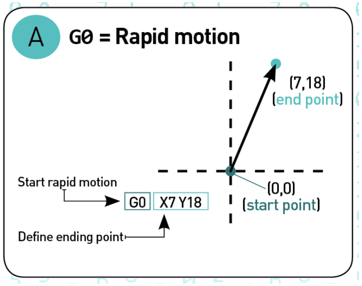
G-code commands #1: G0 or “rapid motion”
The G0 command tells the print head to move at maximum travel speed from the current position to the coordinates specified by the command. The head will move in a coordinated fashion such that both axes complete the travel simultaneously. The nozzle will not extrude any material while executing this command. This G-code command is usually used to bring the nozzle rapidly to some desired coordinates at the start of the print or during the print.
Example: G0 X7 Y18

G-code commands #2: G1 or “controlled motion”
The G1 command tells the print head to move at specified speed from the current position to the coordinated specified by the G-code command. The speed is specified by the Feed rate parameter F. The head will move in a coordinated fashion such that both axes complete the travel simultaneously. The printer can extrude material while executing this G-code command at an extrusion rate specified by the extrusion rate parameter E. Most of the 3D printing happens while executing this command. If you open the G-code file for an actual 3D printing process, you will see a lot of G1 commands.
Example: G1 X7 Y18 F500 E0.02


G-code commands #3: G17/G18/G19 or “set planes”
These G-code commands set the plane in which the nozzle should move. Typically, G17 is the default for most machines and it denotes the X-Y plane. G18 denotes the Z-X plane and G19 denotes the Y-Z plane.
G-code commands #4: G20/G21 or “set units”
These G-code commands set the units. G20 denotes inches while G21 denotes millimeters. This makes a big difference because
means “move rapidly to X=7 inches and Y=18 inches” while
means “move rapidly to X=7 mm and Y=18 mm”.
G-code commands #5: G28 or “homing”
A G28 command tells the machine to go to its home position. A home position can be defined by the G28.1 command as follows.
G-code commands #6: G90 or “absolute mode”
Absolute mode tells the machine to interpret coordinates as absolute coordinates. This means a G-code command
will send the machine head to the coordinate X=10.
G-code commands #7: G91 or “relative mode”
The relative mode is the opposite of the absolute mode. G91 tells the machine to interpret coordinates as relative coordinates. If the machine is currently at X=10, then the following G-code commands
tell the machine to move 10 units in the X direction from its current position. At the end of the operation, the machine head will be located at X=20.
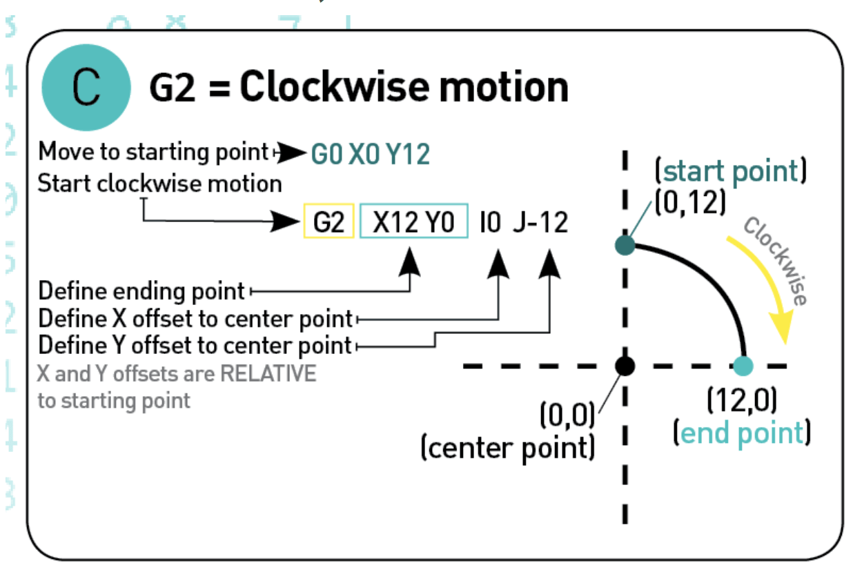
G-code commands #8: G2 or “clockwise motion”
G2 tells the machine to move clockwise starting from its current location. The endpoint is specified by the coordinates X and Y. The center of rotation is specified by the parameter I, which denotes the X offset of the current position from the center of rotation. J denotes the Y offset of the current position from the center of rotation.
Example:

G-code commands #9: G3 or “counterclockwise motion”
Just like the G2 command, the G3 command creates a circular motion but in the counterclockwise direction.
Example:


G-code commands #10: Code comments
If you look at any real world G-code file, you will find that in addition to G-code commands and arguments, it also contains things written in plain English. Here’s an example:
The English text will always be preceded by a semicolon, as you can see in the above line.
Programmers often need to write down explanations in plain English so that other programmers can understand the motivation behind a certain line or section of code. In fact, forget about other programmers! If you are looking at your own code after a year, chances are that you will have forgotten why you coded things in a certain way and would have a hard time figuring things out again.
To solve this problem, you can include code comments. Comments are written after adding a semicolon punctuation mark.You can write anything after adding a semicolon, but most often it is used to explain the rationale behind the code in a human-friendly way. Anything that appears after a semicolon character in a line is ignored by the printer while executing the G-code commands and is only meant for human eyes.
Here is another example of a line that has a code comment.
G-code Commands: The Structure of a Full-fledged Program
We are now in a good position to look at actual code that is used for printing a 3D model.
Most G-code programs contain three important sections. The first section initializes the printer for the printing process. The second section instructs the printer to print the model. The third section resets the printer to its default configuration after the print finishes. Let’s take a look at these sections one by one.
1. Initialization phase
Certain tasks need to be performed before a print can begin. For example, we need to heat the print bed, heat the extruder, purge the nozzle, bring the nozzle to the start position etc. These tasks form the first section of any program.
Here are the first five lines of initialization G-code commands from an actual 3D printing task. You should be in a position to read and understand them at this point, with help from the reference table at the end.
The first line sets the coordinates to absolute positioning. The second line tells the extruder to interpret the extrusion rate as absolute values. The third line turns the fan on, but sets the speed to 0, which essentially means that the fan is off. The fourth line sets the bed temperature to 100 degrees. The fifth line tells the printer to wait till the bed temperature reaches the desired value, in this case, 100.
During the initialization phase, the printer will not extrude any material except when it is purging the nozzle. This is an easy to way to figure out when the initialization phase stops and the actual printing begins. During the actual printing, the printer will be extruding material at almost every step.
2. Printing phase
A 3D printer prints a model layer by layer. Slicers like Simplify3D or Cura typically slices a 3D model into many horizontal layers that stack on top of each other to create the final print.
Therefore, the print phase consists of many movements in the X-Y plane (printing a single layer), then one movement in the Z direction (move to next layer) followed by many movements in the X -Y plane again (print the next layer).
Here is how the G-code commands look like.
3. Reset the printer
Finally, when the printing is over, some final lines of G-code commands bring the printer to a reasonable default state. For example, the nozzle is brought back to the origin, the heating is turned off (both for the bed and the extruder) and the motors are disabled.
G-code Commands: Input and Output
Till now, we have only talked about the computer sending G-code commands to the printer, so it seems like the communication is one way. But 3D printing actually involves a two-way communication between the computer and the printer. Here’s how it works.
When you hit the print button on your computer, the 3D printing software starts sending the G-code commands to the printer, one line at a time. The printer executes the line and responds back to the computer. If the response indicates no error, the computer then sends the next line of code to be executed.
The printer’s response usually follows the following format:
- Ok means that no error has been detected. This prompts the computer to send the next line of code to the printer.
- Rs means “resend the instruction”. This is usually followed by the line number to resend.
- Two exclamation marks(!!) implies hardware error. The machine shuts down immediately in this case and the print job is aborted.
In addition to these 3 responses, the printer might also report printer parameters like temperature, coordinates of the nozzle etc. to the computer.
Temperature is reported in response to a M105 G-Code command. The format of the response is
where T indicates the extruder temperature and B indicates the bed temperature. If the machine does not have a temperature sensor, then -273 is returned as a value.
The coordinates are reported in response to M114 and M117 G-code commands. The format of response is
Here, C stands for “coordinates follow”. This is followed by current X, Y, Z coordinates and other information.
G-code Commands: Visualization Tools
Now that you know how to write G-code, it’s your turn to write some G-code commands and test your understanding. You can use an online visualization tool, where you can write some G-code commands and see the machine head move according to your instructions. It’s a lot of fun! We recommend that you try out this online visualization tool to test your skills.
Slicing software like Simplify3D or Cura also come with a G-code viewer. In the viewer, you will be able to visualize the path of the extruder for actual 3D printing tasks. Check out this must-see video for an excellent demonstration of the G-code viewer in Simplify3D.
G-code Commands: Preventing Print Failures
The G-code viewer can be the difference between a successful and failed print for tricky 3D models. In general, whenever you want to print a complicated 3D model, we advise that you run the viewer and go through the print simulation step by step.
We need to do this because the automatically generated code is often not ideal. You will often find that there are problematic areas that do not have enough support, leading to a failed print. In this case, you need to modify the code to ensure successful printing. Most of the time, this can be done by adding additional support structures using the graphical interface. Here is a video that shows how to do this for a complicated model of a 3D puppy.
G-code Commands: Conclusion
In conclusion, we learned about how a 3D printer prints a CAD model by following an instruction set written in G-code. We learned how to read the G-code commands, and saw some realistic examples. We discussed the most common G-Code commands and some ways of visualizing and testing them. Finally, we introduced G-code viewer, a common feature of Slicers, which can be used to prevent failed prints.
We hope that an understanding of G-code commands helps you become a more knowledgeable and powerful user of your 3D printer. If you found this article useful, share it with other 3D printing enthusiasts and spread the word. Do you have some questions or remarks? Let us know in the comments below!
Appendix 1: Compatibility notes
Each 3D printer comes with a firmware. There are many firmware’s, and developers of these firmware’s tend to implement different flavors of G-code commands. This leads to major compatibility issues. The G-code commands that work for one machine might not work for another.
This problem is usually solved by connecting the Slicer, which generates the code, to a machine specific post-processing driver. The post-processor detects the incoming code flavor and converts the code to the specific flavor^ that the firmware understands.
Therefore, the G-code commands that you see on the Slicer might not necessarily be the code being executed on the machine because of this subtle implementation detail.
Appendix 2: G-code commands
| Code | Description | Milling (M) | Turning (T) | Corollary info |
|---|---|---|---|---|
| G00 | Rapid positioning | M | T | On 2- or 3-axis moves, G00 (unlike G01) traditionally does not necessarily move in a single straight line between start point and end point. It moves each axis at its max speed until its vector quantity is achieved. Shorter vector usually finishes first (given similar axis speeds). This matters because it may yield a dog-leg or hockey-stick motion, which the programmer needs to consider depending on what obstacles are nearby, to avoid a crash. Some machines offer interpolated rapids as a feature for ease of programming (safe to assume a straight line). |
| G01 | Linear interpolation | M | T | The most common workhorse code for feeding during a cut. The program specs the start and end points, and the control automatically calculates (interpolates) the intermediate points to pass through that will yield a straight line (hence „linear“). The control then calculates the angular velocities at which to turn the axis leadscrews via their servomotors or stepper motors. The computer performs thousands of calculations per second, and the motors react quickly to each input. Thus the actual toolpath of the machining takes place with the given feedrate on a path that is accurately linear to within very small limits. |
| G02 | Circular interpolation, clockwise | M | T | Very similar in concept to G01. Again, the control interpolates intermediate points and commands the servo- or stepper motors to rotate the amount needed for the leadscrew to translate the motion to the correct tool tip positioning. This process repeated thousands of times per minute generates the desired toolpath. In the case of G02, the interpolation generates a circle rather than a line. As with G01, the actual toolpath of the machining takes place with the given feedrate on a path that accurately matches the ideal (in G02’s case, a circle) to within very small limits. In fact, the interpolation is so precise (when all conditions are correct) that milling an interpolated circle can obviate operations such as drilling, and often even fine boring. Addresses for radius or arc center: G02 and G03 take either an R address (for the radius desired on the part) or IJK addresses (for the component vectors that define the vector from the arc start point to the arc center point). Cutter comp: On most controls you cannot start G41 or G42 in G02 or G03 modes. You must already have compensated in an earlier G01 block. Often a short linear lead-in movement will be programmed, merely to allow cutter compensation before the main event, the circle-cutting, begins. Full circles: When the arc start point and the arc end point are identical, a 360° arc, a full circle, will be cut. (Some older controls cannot support this because arcs cannot cross between quadrants of the cartesian system. Instead, four quarter-circle arcs are programmed back-to-back.) |
| G03 | Circular interpolation, counterclockwise | M | T | Same corollary info as for G02. |
| G04 | Dwell | M | T | Takes an address for dwell period (may be X, U, or P). The dwell period is specified by a control parameter, typically set to milliseconds. Some machines can accept either X1.0 (s) or P1000 (ms), which are equivalent. Choosing dwell duration: Often the dwell needs only to last one or two full spindle rotations. This is typically much less than one second. Be aware when choosing a duration value that a long dwell is a waste of cycle time. In some situations it won’t matter, but for high-volume repetitive production (over thousands of cycles), it is worth calculating that perhaps you only need 100 ms, and you can call it 200 to be safe, but 1000 is just a waste (too long). |
| G05 P10000 | High-precision contour control (HPCC) | M | Uses a deep look-ahead buffer and simulation processing to provide better axis movement acceleration and deceleration during contour milling | |
| G05.1 Q1. | AI Advanced Preview Control | M | Uses a deep look-ahead buffer and simulation processing to provide better axis movement acceleration and deceleration during contour milling | |
| G06.1 | Non-uniform rational B-spline (NURBS) Machining | M | Activates Non-Uniform Rational B Spline for complex curve and waveform machining (this code is confirmed in Mazatrol 640M ISO Programming) | |
| G07 | Imaginary axis designation | M | ||
| G09 | Exact stop check, non-modal | M | T | The modal version is G61. |
| G10 | Programmable data input | M | T | Modifies the value of work coordinate and tool offsets |
| G11 | Data write cancel | M | T | |
| G12 | Full-circle interpolation, clockwise | M | Fixed cycle for ease of programming 360° circular interpolation with blend-radius lead-in and lead-out. Not standard on Fanuc controls. | |
| G13 | Full-circle interpolation, counterclockwise | M | Fixed cycle for ease of programming 360° circular interpolation with blend-radius lead-in and lead-out. Not standard on Fanuc controls. | |
| G17 | XY plane selection | M | ||
| G18 | ZX plane selection | M | T | On most CNC lathes (built 1960s to 2000s), ZX is the only available plane, so no G17 to G19 codes are used. This is now changing as the era begins in which live tooling, multitask/multifunction, and mill-turn/turn-mill gradually become the „new normal“. But the simpler, traditional form factor will probably not disappear—it will just move over to make room for the newer configurations. See also V address. |
| G19 | YZ plane selection | M | ||
| G20 | Programming in inches | M | T | Somewhat uncommon except in USA and (to lesser extent) Canada and UK. However, in the global marketplace, competence with both G20 and G21 always stands some chance of being necessary at any time. The usual minimum increment in G20 is one ten-thousandth of an inch (0.0001″), which is a larger distance than the usual minimum increment in G21 (one thousandth of a millimeter, .001 mm, that is, one micrometre). This physical difference sometimes favors G21 programming. |
| G21 | Programming in millimeters (mm) | M | T | Prevalent worldwide. However, in the global marketplace, competence with both G20 and G21 always stands some chance of being necessary at any time. |
| G28 | Return to home position (machine zero, aka machine reference point) | M | T | Takes X Y Z addresses which define the intermediate point that the tool tip will pass through on its way home to machine zero. They are in terms of part zero (aka program zero), NOT machine zero. |
| G30 | Return to secondary home position (machine zero, aka machine reference point) | M | T | Takes a P address specifying which machine zero point is desired, if the machine has several secondary points (P1 to P4). Takes X Y Z addresses which define the intermediate point that the tool tip will pass through on its way home to machine zero. They are in terms of part zero (aka program zero), NOT machine zero. |
| G31 | Skip function (used for probes and tool length measurement systems) | M | ||
| G32 | Single-point threading, longhand style (if not using a cycle, e.g., G76) | T | Similar to G01 linear interpolation, except with automatic spindle synchronization for single-point threading. | |
| G33 | Constant-pitch threading | M | ||
| G33 | Single-point threading, longhand style (if not using a cycle, e.g., G76) | T | Some lathe controls assign this mode to G33 rather than G32. | |
| G34 | Variable-pitch threading | M | ||
| G40 | Tool radius compensation off | M | T | Turn off cutter radius compensation (CRC). Cancels G41 or G42. |
| G41 | Tool radius compensation left | M | T | Turn on cutter radius compensation (CRC), left, for climb milling. Milling: Given righthand-helix cutter and M03 spindle direction, G41 corresponds to climb milling (down milling). Takes an address (D or H) that calls an offset register value for radius. Turning: Often needs no D or H address on lathes, because whatever tool is active automatically calls its geometry offsets with it. (Each turret station is bound to its geometry offset register.) G41 and G42 for milling has been partially automated and obviated (although not completely) since CAM programming has become more common. CAM systems allow the user to program as if with a zero-diameter cutter. The fundamental concept of cutter radius compensation is still in play (i.e., that the surface produced will be distance R away from the cutter center), but the programming mindset is different; the human does not choreograph the toolpath with conscious, painstaking attention to G41, G42, and G40, because the CAM software takes care of it. The software has various CRC mode selections, such as computer, control, wear, reverse wear, off, some of which do not use G41/G42 at all (good for roughing, or wide finish tolerances), and others which use it so that the wear offset can still be tweaked at the machine (better for tight finish tolerances). |
| G42 | Tool radius compensation right | M | T | Turn on cutter radius compensation (CRC), right, for conventional milling. Similar corollary info as for G41. Given righthand-helix cutter and M03 spindle direction, G42 corresponds to conventional milling (up milling). |
| G43 | Tool height offset compensation negative | M | Takes an address, usually H, to call the tool length offset register value. The value is negative because it will be added to the gauge line position. G43 is the commonly used version (vs G44). | |
| G44 | Tool height offset compensation positive | M | Takes an address, usually H, to call the tool length offset register value. The value is positive because it will be subtracted from the gauge line position. G44 is the seldom-used version (vs G43). | |
| G45 | Axis offset single increase | M | ||
| G46 | Axis offset single decrease | M | ||
| G47 | Axis offset double increase | M | ||
| G48 | Axis offset double decrease | M | ||
| G49 | Tool length offset compensation cancel | M | Cancels G43 or G44. | |
| G50 | Define the maximum spindle speed | T | Takes an S address integer which is interpreted as rpm. Without this feature, G96 mode (CSS) would rev the spindle to „wide open throttle“ when closely approaching the axis of rotation. | |
| G50 | Scaling function cancel | M | ||
| G50 | Position register (programming of vector from part zero to tool tip) | T | Position register is one of the original methods to relate the part (program) coordinate system to the tool position, which indirectly relates it to the machine coordinate system, the only position the control really „knows“. Not commonly programmed anymore because G54 to G59 (WCSs) are a better, newer method. Called via G50 for turning, G92 for milling. Those G addresses also have alternate meanings (which see). Position register can still be useful for datum shift programming. The „manual absolute“ switch, which has very few useful applications in WCS contexts, was more useful in position register contexts, because it allowed the operator to move the tool to a certain distance from the part (for example, by touching off a 2.0000″ gage) and then declare to the control what the distance-to-go shall be (2.0000). | |
| G52 | Local coordinate system (LCS) | M | Temporarily shifts program zero to a new location. It is simply „an offset from an offset“, that is, an additional offset added onto the WCS offset. This simplifies programming in some cases. The typical example is moving from part to part in a multipart setup. With G54 active, G52 X140.0 Y170.0 shifts program zero 140 mm over in X and 170 mm over in Y. When the part „over there“ is done, G52 X0 Y0 returns program zero to normal G54 (by reducing G52 offset to nothing). The same result can also be achieved (1) using multiple WCS origins, G54/G55/G56/G57/G58/G59; (2) on newer controls, G54.1 P1/P2/P3/etc. (all the way up to P48); or (3) using G10 for programmable data input, in which the program can write new offset values to the offset registers. Which method to use depends on shop-specific application. | |
| G53 | Machine coordinate system | M | T | Takes absolute coordinates (X,Y,Z,A,B,C) with reference to machine zero rather than program zero. Can be helpful for tool changes. Nonmodal and absolute only. Subsequent blocks are interpreted as „back to G54“ even if it is not explicitly programmed. |
| G54 to G59 | Work coordinate systems (WCSs) | M | T | Have largely replaced position register (G50 and G92). Each tuple of axis offsets relates program zero directly to machine zero. Standard is 6 tuples (G54 to G59), with optional extensibility to 48 more via G54.1 P1 to P48. |
| G54.1 P1 to P48 | Extended work coordinate systems | M | T | Up to 48 more WCSs besides the 6 provided as standard by G54 to G59. Note floating-point extension of G-code data type (formerly all integers). Other examples have also evolved (e.g., G84.2). Modern controls have the hardware to handle it. |
| G61 | Exact stop check, modal | M | T | Can be canceled with G64. The non-modal version is G09. |
| G62 | Automatic corner override | M | T | |
| G64 | Default cutting mode (cancel exact stop check mode) | M | T | Cancels G61. |
| G68 | Rotate coordinate system. | M | Rotates coordinate system in the current plane given with G17 G18 or G19. Center of rotation is given with two parameters, which vary with each vendors implementation. Rotate with angle given with argument R. This can be for instance be used to align coordinate system with misaligned part. It can also be used to repeat movement sequences around a center. Not all vendors support coordinate system rotation. | |
| G69 | Turn off coordinate system rotation. | M | Cancels G68. | |
| G70 | Fixed cycle, multiple repetitive cycle, for finishing (including contours) | T | ||
| G71 | Fixed cycle, multiple repetitive cycle, for roughing (Z-axis emphasis) | T | ||
| G72 | Fixed cycle, multiple repetitive cycle, for roughing (X-axis emphasis) | T | ||
| G73 | Fixed cycle, multiple repetitive cycle, for roughing, with pattern repetition | T | ||
| G73 | Peck drilling cycle for milling – high-speed (NO full retraction from pecks) | M | Retracts only as far as a clearance increment (system parameter). For when chipbreaking is the main concern, but chip clogging of flutes is not. Compare G83. | |
| G74 | Peck drilling cycle for turning | T | ||
| G74 | Tapping cycle for milling, lefthand thread, M04 spindle direction | M | See notes at G84. | |
| G75 | Peck grooving cycle for turning | T | ||
| G76 | Fine boring cycle for milling | M | Includes OSS and shift (oriented spindle stop and shift tool off centerline for retraction) | |
| G76 | Threading cycle for turning, multiple repetitive cycle | T | ||
| G80 | Cancel canned cycle | M | T | Milling: Cancels all cycles such as G73, G81, G83, etc. Z-axis returns either to Z-initial level or R level, as programmed (G98 or G99, respectively). Turning: Usually not needed on lathes, because a new group-1 G address (G00 to G03) cancels whatever cycle was active. |
| G81 | Simple drilling cycle | M | No dwell built in | |
| G82 | Drilling cycle with dwell | M | Dwells at hole bottom (Z-depth) for the number of milliseconds specified by the P address. Good for when hole bottom finish matters. Good for spot drilling because the divot will be certain to clean up evenly. Consider the „choosing dwell duration“ note at G04. | |
| G83 | Peck drilling cycle (full retraction from pecks) | M | Returns to R-level after each peck. Good for clearing flutes of chips. Compare G73. | |
| G84 | Tapping cycle, righthand thread, M03 spindle direction | M | G74 and G84 are the righthand and lefthand „pair“ for old-school tapping with a non-rigid toolholder („tapping head“ style). Compare the rigid tapping „pair“, G84.2 and G84.3. | |
| G84.2 | Tapping cycle, righthand thread, M03 spindle direction, rigid toolholder | M | See notes at G84. Rigid tapping synchronizes speed and feed according to the desired thread helix. That is, it synchronizes degrees of spindle rotation with microns of axial travel. Therefore, it can use a rigid toolholder to hold the tap. This feature is not available on old machines or newer low-end machines, which must use „tapping head“ motion (G74/G84). | |
| G84.3 | Tapping cycle, lefthand thread, M04 spindle direction, rigid toolholder | M | See notes at G84 and G84.2. | |
| G85 | boring cycle, feed in/feed out | M | – Good cycle for a reamer. – In some cases good for single-point boring tool, although in other cases the lack of depth of cut on the way back out is bad for surface finish, in which case, G76 (OSS/shift) can be used instead. – If need dwell at hole bottom, see G89. |
|
| G86 | boring cycle, feed in/spindle stop/rapid out | M | Boring tool will leave a slight score mark on the way back out. Appropriate cycle for some applications; for others, G76 (OSS/shift) can be used instead. | |
| G87 | boring cycle, backboring | M | For backboring. Returns to initial level only (G98); this cycle cannot use G99 because its R level is on the far side of the part, away from the spindle headstock. | |
| G88 | boring cycle, feed in/spindle stop/manual operation | M | ||
| G89 | boring cycle, feed in/dwell/feed out | M | G89 is like G85 but with dwell added at bottom of hole. | |
| G90 | Absolute programming | M | T (B) | Positioning defined with reference to part zero. Milling: Always as above. Turning: Sometimes as above (Fanuc group type B and similarly designed), but on most lathes (Fanuc group type A and similarly designed), G90/G91 are not used for absolute/incremental modes. Instead, U and W are the incremental addresses and X and Z are the absolute addresses. On these lathes, G90 is instead a fixed cycle address for roughing. |
| G90 | Fixed cycle, simple cycle, for roughing (Z-axis emphasis) | T (A) | When not serving for absolute programming (above) | |
| G91 | Incremental programming | M | T (B) | Positioning defined with reference to previous position. Milling: Always as above. Turning: Sometimes as above (Fanuc group type B and similarly designed), but on most lathes (Fanuc group type A and similarly designed), G90/G91 are not used for absolute/incremental modes. Instead, U and W are the incremental addresses and X and Z are the absolute addresses. On these lathes, G90 is a fixed cycle address for roughing. |
| G92 | Position register (programming of vector from part zero to tool tip) | M | T (B) | Same corollary info as at G50 position register. Milling: Always as above. Turning: Sometimes as above (Fanuc group type B and similarly designed), but on most lathes (Fanuc group type A and similarly designed), position register is G50. |
| G92 | Threading cycle, simple cycle | T (A) | ||
| G94 | Feedrate per minute | M | T (B) | On group type A lathes, feedrate per minute is G98. |
| G94 | Fixed cycle, simple cycle, for roughing (X-axis emphasis) | T (A) | When not serving for feedrate per minute (above) | |
| G95 | Feedrate per revolution | M | T (B) | On group type A lathes, feedrate per revolution is G99. |
| G96 | Constant surface speed (CSS) | T | Varies spindle speed automatically to achieve a constant surface speed. See speeds and feeds. Takes an S address integer, which is interpreted as sfm in G20 mode or as m/min in G21 mode. | |
| G97 | Constant spindle speed | M | T | Takes an S address integer, which is interpreted as rev/min (rpm). The default speed mode per system parameter if no mode is programmed. |
| G98 | Return to initial Z level in canned cycle | M | ||
| G98 | Feedrate per minute (group type A) | T (A) | Feedrate per minute is G94 on group type B. | |
| G99 | Return to R level in canned cycle | M | ||
| G99 | Feedrate per revolution (group type A) | T (A) | Feedrate per revolution is G95 on group type B. |
(source: Wikipedia)
Appendix 3: M-Code commands
| Code | Description | Milling (M) | Turning (T) | Corollary info |
|---|---|---|---|---|
| M00 | Compulsory stop | M | T | Non-optional—machine will always stop upon reaching M00 in the program execution. |
| M01 | Optional stop | M | T | Machine will only stop at M01 if operator has pushed the optional stop button. |
| M02 | End of program | M | T | Program ends; execution may or may not return to program top (depending on the control); may or may not reset register values. M02 was the original program-end code, now considered obsolete, but still supported for backward compatibility.[7] Many modern controls treat M02 as equivalent to M30.[7] See M30 for additional discussion of control status upon executing M02 or M30. |
| M03 | Spindle on (clockwise rotation) | M | T | The speed of the spindle is determined by the address S, in either revolutions per minute (G97 mode; default) or surface feet per minute or meters per minute (G96 mode under either G20 or G21). The right-hand rule can be used to determine which direction is clockwise and which direction is counter-clockwise. Right-hand-helix screws moving in the tightening direction (and right-hand-helix flutes spinning in the cutting direction) are defined as moving in the M03 direction, and are labeled „clockwise“ by convention. The M03 direction is always M03 regardless of local vantage point and local CW/CCW distinction. |
| M04 | Spindle on (counterclockwise rotation) | M | T | See comment above at M03. |
| M05 | Spindle stop | M | T | |
| M06 | Automatic tool change (ATC) | M | T (sometimes) | Many lathes do not use M06 because the T address itself indexes the turret. Programming on any particular machine tool requires knowing which method that machine uses. To understand how the T address works and how it interacts (or not) with M06, one must study the various methods, such as lathe turret programming, ATC fixed tool selection, ATC random memory tool selection, the concept of „next tool waiting“, and empty tools. |
| M07 | Coolant on (mist) | M | T | |
| M08 | Coolant on (flood) | M | T | |
| M09 | Coolant off | M | T | |
| M10 | Pallet clamp on | M | For machining centers with pallet changers | |
| M11 | Pallet clamp off | M | For machining centers with pallet changers | |
| M13 | Spindle on (clockwise rotation) and coolant on (flood) | M | This one M-code does the work of both M03 and M08. It is not unusual for specific machine models to have such combined commands, which make for shorter, more quickly written programs. | |
| M19 | Spindle orientation | M | T | Spindle orientation is more often called within cycles (automatically) or during setup (manually), but it is also available under program control via M19. The abbreviation OSS (oriented spindle stop) may be seen in reference to an oriented stop within cycles. |
| M21 | Mirror, X-axis | M | ||
| M21 | Tailstock forward | T | ||
| M22 | Mirror, Y-axis | M | ||
| M22 | Tailstock backward | T | ||
| M23 | Mirror OFF | M | ||
| M23 | Thread gradual pullout ON | T | ||
| M24 | Thread gradual pullout OFF | T | ||
| M30 | End of program, with return to program top | M | T | Today M30 is considered the standard program-end code, and will return execution to the top of the program. Today most controls also still support the original program-end code, M02, usually by treating it as equivalent to M30. Additional info: Compare M02 with M30. First, M02 was created, in the days when the punched tape was expected to be short enough to be spliced into a continuous loop (which is why on old controls, M02 triggered no tape rewinding).[7] The other program-end code, M30, was added later to accommodate longer punched tapes, which were wound on a reel and thus needed rewinding before another cycle could start.[7] On many newer controls, there is no longer a difference in how the codes are executed—both act like M30. |
| M41 | Gear select – gear 1 | T | ||
| M42 | Gear select – gear 2 | T | ||
| M43 | Gear select – gear 3 | T | ||
| M44 | Gear select – gear 4 | T | ||
| M48 | Feedrate override allowed | M | T | |
| M49 | Feedrate override NOT allowed | M | T | Prevent MFO. This rule is also usually called (automatically) within tapping cycles or single-point threading cycles, where feed is precisely correlated to speed. Same with spindle speed override (SSO) and feed hold button. Some controls are capable of providing SSO and MFO during threading. |
| M52 | Unload Last tool from spindle | M | T | Also empty spindle. |
| M60 | Automatic pallet change (APC) | M | For machining centers with pallet changers | |
| M98 | Subprogram call | M | T | Takes an address P to specify which subprogram to call, for example, „M98 P8979“ calls subprogram O8979. |
| M99 | Subprogram end | M | T | Usually placed at end of subprogram, where it returns execution control to the main program. The default is that control returns to the block following the M98 call in the main program. Return to a different block number can be specified by a P address. M99 can also be used in main program with block skip for endless loop of main program on bar work on lathes (until operator toggles block skip). |
(Source: Wikipedia)
Website: LINK
