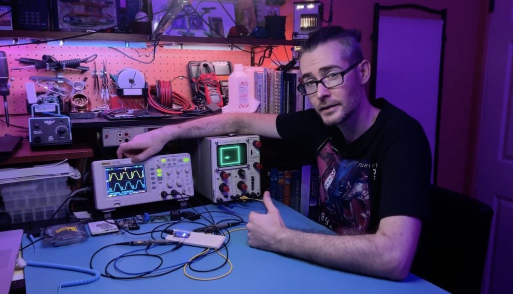
Unless you’re very young, then you probably remember watching a CRT (cathode-ray tube) television. Those work by directing an electron beam very quickly along row after row while pulsing power to create raster images. But it is also possible to create vector images by directing the electron beam along paths instead of scanning, which you might notice is what an oscilloscope does. Trevor combined these two ideas and made a video explaining how you can create vector video art with an Arduino, a handful of resistors, and an oscilloscope.
A conventional analog oscilloscope contains a CRT just like an old tube TV. But instead of sweeping the electron beam to scan line by line, they direct the beam according to the voltage of the input signals. One signal pushes the beam up and down in the Y axis, while the second signal pushes the beam left and right in the X axis. That is useful for visualizing electrical signals for analysis, but it also means that controlling the position of the electron beam is as simple as adjusting the voltage of the oscilloscope’s input signals.
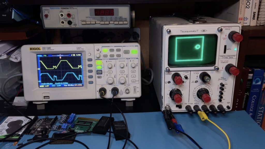
Not all oscilloscopes give users the ability to adjust the strength of the electron beam, or even to turn it off. For that reason, Trevor’s tutorial relies on timing to control intensity. If the beam remains in a location for a long time, it will produce a brighter spot. If it jumps quickly from one location to another, it will produce almost no light along the path.
On the hardware side, an Arduino Nano board outputs the X and Y signals to the oscilloscope through resistor ladders (each connected to several pins) that act as DACs (digital-to-analog converters). The DACs are necessary because digital signals only output as HIGH (5V) or LOW (0V) and wouldn’t be able to direct the electron beam anywhere in-between. Trevor’s code includes functions to help users draw using those outputs, with some very impressive results.
- Werbung -
Hier klicken, um den Inhalt von YouTube anzuzeigen.
Erfahre mehr in der Datenschutzerklärung von YouTube.